EP1366950A2 - Arretiervorrichtung für Sitzkraftheber - Google Patents
Arretiervorrichtung für Sitzkraftheber Download PDFInfo
- Publication number
- EP1366950A2 EP1366950A2 EP03011750A EP03011750A EP1366950A2 EP 1366950 A2 EP1366950 A2 EP 1366950A2 EP 03011750 A EP03011750 A EP 03011750A EP 03011750 A EP03011750 A EP 03011750A EP 1366950 A2 EP1366950 A2 EP 1366950A2
- Authority
- EP
- European Patent Office
- Prior art keywords
- sector gear
- cushion
- frame
- respect
- frames
- Prior art date
- Legal status (The legal status is an assumption and is not a legal conclusion. Google has not performed a legal analysis and makes no representation as to the accuracy of the status listed.)
- Withdrawn
Links
Images




Classifications
-
- B—PERFORMING OPERATIONS; TRANSPORTING
- B60—VEHICLES IN GENERAL
- B60N—SEATS SPECIALLY ADAPTED FOR VEHICLES; VEHICLE PASSENGER ACCOMMODATION NOT OTHERWISE PROVIDED FOR
- B60N2/00—Seats specially adapted for vehicles; Arrangement or mounting of seats in vehicles
- B60N2/02—Seats specially adapted for vehicles; Arrangement or mounting of seats in vehicles the seat or part thereof being movable, e.g. adjustable
- B60N2/04—Seats specially adapted for vehicles; Arrangement or mounting of seats in vehicles the seat or part thereof being movable, e.g. adjustable the whole seat being movable
- B60N2/16—Seats specially adapted for vehicles; Arrangement or mounting of seats in vehicles the seat or part thereof being movable, e.g. adjustable the whole seat being movable height-adjustable
- B60N2/1605—Seats specially adapted for vehicles; Arrangement or mounting of seats in vehicles the seat or part thereof being movable, e.g. adjustable the whole seat being movable height-adjustable characterised by the cinematic
- B60N2/161—Rods
- B60N2/1615—Parallelogram-like structure
-
- B—PERFORMING OPERATIONS; TRANSPORTING
- B60—VEHICLES IN GENERAL
- B60N—SEATS SPECIALLY ADAPTED FOR VEHICLES; VEHICLE PASSENGER ACCOMMODATION NOT OTHERWISE PROVIDED FOR
- B60N2/00—Seats specially adapted for vehicles; Arrangement or mounting of seats in vehicles
- B60N2/02—Seats specially adapted for vehicles; Arrangement or mounting of seats in vehicles the seat or part thereof being movable, e.g. adjustable
- B60N2/04—Seats specially adapted for vehicles; Arrangement or mounting of seats in vehicles the seat or part thereof being movable, e.g. adjustable the whole seat being movable
- B60N2/16—Seats specially adapted for vehicles; Arrangement or mounting of seats in vehicles the seat or part thereof being movable, e.g. adjustable the whole seat being movable height-adjustable
- B60N2/1635—Seats specially adapted for vehicles; Arrangement or mounting of seats in vehicles the seat or part thereof being movable, e.g. adjustable the whole seat being movable height-adjustable characterised by the drive mechanism
- B60N2/165—Gear wheel driven mechanism
-
- B—PERFORMING OPERATIONS; TRANSPORTING
- B60—VEHICLES IN GENERAL
- B60N—SEATS SPECIALLY ADAPTED FOR VEHICLES; VEHICLE PASSENGER ACCOMMODATION NOT OTHERWISE PROVIDED FOR
- B60N2/00—Seats specially adapted for vehicles; Arrangement or mounting of seats in vehicles
- B60N2/02—Seats specially adapted for vehicles; Arrangement or mounting of seats in vehicles the seat or part thereof being movable, e.g. adjustable
- B60N2/04—Seats specially adapted for vehicles; Arrangement or mounting of seats in vehicles the seat or part thereof being movable, e.g. adjustable the whole seat being movable
- B60N2/16—Seats specially adapted for vehicles; Arrangement or mounting of seats in vehicles the seat or part thereof being movable, e.g. adjustable the whole seat being movable height-adjustable
- B60N2/168—Seats specially adapted for vehicles; Arrangement or mounting of seats in vehicles the seat or part thereof being movable, e.g. adjustable the whole seat being movable height-adjustable and provided with braking systems
Definitions
- the present invention relates to a stopper structure for a seat lifter for adjusting the seat height.
- the seat lifter comprises a pinion gear, a sector gear meshed therewith, and a link swingably provided to the sector gear, wherein the sector gear is rotated in response to input out of the pinion gear to cause swinging of the link, thus adjusting the seat height.
- the pinion gear includes a shaft fixing portion integrated with a base forming member
- the sector gear includes a rotation shaft integrated therewith
- assembling is carried out such that the rotation shaft of the sector gear is mounted to the base forming member with the sector gear not meshed with the pinion gear, then, the sector gear is rotated to mesh with the pinion gear.
- the sector gear With the sector gear mounted to the pinion gear in such a manner, however, the sector gear needs an additional part such as a stopper pin or additional machining after assembling so as to prevent disengagement of the sector gear from the pinion gear.
- an object of the present invention to provide a stopper structure for a seat lifter, which can prevent disengagement of the sector gear from the pinion gear with enhanced assembling efficiency and reduced manufacturing cost.
- the present invention provides generally a stopper structure for a seat lifter, which comprises: a base frame; a bell crank rotatably mounted to the base frame; a cushion frame linked with one swinging end of the bell crank; a pinion gear rotatably mounted to one of the base frame and the cushion frame; a connecting shaft rotatably mounted to the one of the base frame and the cushion frame; a sector gear meshed with the pinion gear, the sector gear being fixed to the connecting shaft, the sector gear being rotated to swing the bell crank for upward and downward movement of the cushion frame with respect to the base frame; a connecting rod having one end linked with another swinging end of the bell crank and another end linked with the sector gear in a position offset with respect to the connecting shaft; and a stopper formed at the another end of the connecting rod, the stopper abutting on the connecting shaft when the cushion frame is located in at least one of a lifting limit position and a lowering limit position with respect to the base frame, when the cushion frame is located in the lifting limit position the stopper restricting
- FIG. 1 is an exploded perspective view showing a seat lifter provided with a stopper structure embodying the present invention
- FIG. 2 is a side view showing the seat lifter
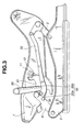
- FIG. 3 is a perspective view showing a driving-side cushion frame located in a lifting limit position with respect to a driving-side base frame;
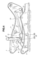
- FIG. 4 is a view similar to FIG. 3, showing the driving-side cushion frame located in a middle position with respect to the driving-side base frame;
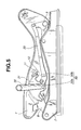
- FIG. 5 is a view similar to FIG. 4, showing the driving-side cushion frame located in a lowering limit position with respect to the driving-side base frame;
- FIG. 6 is a view similar to FIG. 5, showing a driven-side cushion frame located in a lifting limit position with respect to a driven-side base frame;
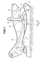
- FIG. 7 is a view similar to FIG. 6, showing the driven-side cushion frame located in a middle position with respect to the driven-side base frame;
- FIG. 8 is a view similar to FIG. 7, showing the driven-side cushion frame located in a lowering limit position with respect to the driven-side base frame.
- a seat lifter 1 comprises a driving-side or first base frame 2 and a driving-side or first bell crank 3 rotatably mounted at a rear end of the base frame 2 through a rear link pin 4.
- One swinging end of the driving-side bell crank 3 is rotatably mounted at a rear end of the driving-side cushion frame 7 through a bush 5 and a rear link pin 6.
- a driving-side or first link 8 has one end rotatably mounted at a front end of the driving-side base frame 2 through a front link pin 9. Another end of the driving-side link 8 is rotatably mounted at a front end of the driving-side cushion frame 7 through a front link pin 10.
- a pinion gear 11 is mounted at one side face of the driving-side cushion frame 7.
- the pinion gear 11 is rotatably supported in a hole formed in the driving-side cushion frame 7, and has teeth partly exposed at another side face of the cushion frame 7 through a recessed hole 12.
- the pinion gear 11 is rotated by rotating an operation knob (not shown), rotation of which is restricted by a brake mechanism 13 except when operating the operation knob.
- a driven-side or second bell crank 16 of substantially the same shape as the driving-side bell crank 3 is rotatably mounted at a rear end of a driven-side or second base frame 15 through a rear link pin 17.
- One swinging end of the driven-side bell crank 16 is rotatably mounted at a rear end of a driven-side or second cushion frame 20 through a bush 18 and rear link pin 19.
- a driven-side or second link 21 has one end rotatably mounted at a front end of the driven-side base frame 15 through a front link pin 22. Another end of the driven-side link 21 is rotatably mounted at a front end of the driven-side cushion frame 20 through a front link pin 23.
- the driving-side link 8 and the driven-side link 21 are coupled through a connecting pipe 24.
- the connecting pipe 24 has one end fixed to the driving-side link 8 through a screw 24a and a nut 26a, and another end fixed to the driven-side link 21 through a screw 25b and a nut 26b.
- the driving-side cushion frame 7 and the driven-side cushion frame 20 are coupled through a connecting shaft 30.
- the connecting shaft 30 has one end rotatably mounted in a hole formed in a side face (another side face) of the driving-side cushion frame 7, and another end rotatably mounted in a hole formed in a side face of the driven-side cushion frame 20.
- a sector gear 31 is fixed at one end of the connecting shaft 30 to mesh with the pinion gear 11, whereas a connecting link 32 is fixed at another end thereof.
- the sector gear 31 is linked with the driving-side bell crank 3 through a driving-side or first connecting rod 33.
- the driving-side connecting rod 33 has one end rotatably mounted at another swinging end of the driving-side bell crank 3 through a connecting pin 34 and a bush 35.
- Another end of the driving-side connecting rod 33 having a protrusion 36 is rotatably mounted to the sector gear 31 in a position offset with respect to the connecting shaft 30 through a connecting pin 37 and a push nut 38.
- a driving-side or first stopper 50 is formed at one end of the driving-side connecting rod 33 to restrict rotation of the sector gear 31.
- the driving-side stopper 50 comprises a lowering-side stopper portion 50a and lifting-side stopper portion 50b as will be described in detail later.
- the connecting link 32 is linked with the driven-side bell crank 16 through a driven-side or second connecting rod 40 of substantially the same shape as the driving-side connecting rod 33.
- the driven-side connecting rod 40 has one end rotatably mounted at another swinging end of the driven-side bell crank 16 through a connecting pin 41 and a bush 42.
- another end of the driven-side connecting rod 40 having a protrusion 43 is rotatably mounted to the connecting link 32 in a position offset with respect to the connecting shaft 30 through a connecting pin 44 and a push nut 45.
- the offset amount of the driven-side connecting rod 40 with respect to the connecting shaft 30 is equal to that of the driving-side connecting rod 33 with respect thereto.
- the sector gear 31 is fixed to the connecting shaft 30, the sector gear 31 and the pinion gear 11 are assembled such that both ends of the connecting shaft 30 are inserted into the holes of the driving-side cushion frame 7 and the driven-side cushion frame 20, then, the sector gear 31 is rotated to mesh the sector gear 31 with the pinion gear 11. After assembling the sector gear 31 and the pinion gear 11, the driving-side connecting rod 33 and the driven-side connecting rod 40 are mounted, respectively.
- the connecting shaft 30 is also rotated, so that the driven-side connecting rod 40 linked with the connecting link 32 is swung to cause swinging of the driven-side bell crank 16, thus having upward/downward movement of the driven-side cushion frame 20 with respect to the driven-side base frame 15.
- Upward/downward movement of the driving-side cushion frame 7 with respect to the driving-side base frame 2 is synchronized with that of the driven-side cushion frame 20 with respect to the driven-side base frame 15.
- the driving-side stopper 50 comprising the lifting-side stopper portion 50b and the lowering-side stopper portion 50a formed at another end of the driving-side connecting rod 33 restricts rotation of the sector gear 31.
- a driven-side or second stopper 51 comprising lifting-side stopper portion 51b and lowering-side stopper portion 51 a formed at another end of the driven-side connecting rod 40 restricts rotation of the connecting link 32.
- the structure of making the driving-side connecting rod 33 and the driven-side connecting rod 40 abut on the connecting shaft 30 can prevent disengagement of the sector gear 31 from the pinion gear 11. This results in no need of an additional part such as a stopper pin or additional machining after assembling so as to prevent disengagement of the sector gear 31 from the pinion gear 11, allowing a reduction in manufacturing cost.
- the present invention is not limited thereto, and various changes and modifications can be made without departing from the scope of the present invention.
- the driving-side connecting rod 33 and the driven-side connecting rod 40 abut on the connecting shaft 30 from below.
- the driving-side connecting rod 33 and the driven-side connecting rod 40 may abut on the connecting shaft 30 from above by appropriately changing a mounting position of the driving-side connecting rod 33 with respect to the sector gear 31 and that of the driven-side connecting rod 40 with respect to the connecting link 32
Landscapes
- Engineering & Computer Science (AREA)
- Aviation & Aerospace Engineering (AREA)
- Transportation (AREA)
- Mechanical Engineering (AREA)
- Seats For Vehicles (AREA)
Applications Claiming Priority (2)
| Application Number | Priority Date | Filing Date | Title |
|---|---|---|---|
| JP2002158469A JP4040910B2 (ja) | 2002-05-31 | 2002-05-31 | シートリフターのストッパー構造 |
| JP2002158469 | 2002-05-31 |
Publications (2)
| Publication Number | Publication Date |
|---|---|
| EP1366950A2 true EP1366950A2 (de) | 2003-12-03 |
| EP1366950A3 EP1366950A3 (de) | 2006-05-24 |
Family
ID=29417238
Family Applications (1)
| Application Number | Title | Priority Date | Filing Date |
|---|---|---|---|
| EP03011750A Withdrawn EP1366950A3 (de) | 2002-05-31 | 2003-05-23 | Arretiervorrichtung für Sitzkraftheber |
Country Status (3)
| Country | Link |
|---|---|
| US (1) | US6729594B2 (de) |
| EP (1) | EP1366950A3 (de) |
| JP (1) | JP4040910B2 (de) |
Cited By (2)
| Publication number | Priority date | Publication date | Assignee | Title |
|---|---|---|---|---|
| EP3023292A4 (de) * | 2013-07-14 | 2017-03-08 | Delta Tooling Co., Ltd. | Hebemechanismus und fahrzeugsitz |
| CN109457579A (zh) * | 2018-12-21 | 2019-03-12 | 合肥佳恩特机械制造有限公司 | 一种新型可调式压路机车架 |
Families Citing this family (9)
| Publication number | Priority date | Publication date | Assignee | Title |
|---|---|---|---|---|
| FR2844752B1 (fr) * | 2002-09-19 | 2004-11-05 | Airbus France | Dispositif et systeme pour le filtrage des mouvements vibratoires d'un support de passager, et support de passager equipe d'un tel systeme |
| DE102004055535B3 (de) * | 2004-11-17 | 2006-07-20 | Johnson Controls Gmbh | Strukturelement für einen Sitz, insbesondere für einen Kraftfahrzeugsitz |
| JP4883441B2 (ja) | 2006-05-19 | 2012-02-22 | テイ・エス テック株式会社 | 自動車用シートの高さ調整装置 |
| DE102010044055B4 (de) * | 2010-11-17 | 2021-05-06 | Brose Fahrzeugteile SE & Co. Kommanditgesellschaft, Coburg | Fahrzeugsitzgestell |
| JP2013035520A (ja) * | 2011-08-10 | 2013-02-21 | Ts Tech Co Ltd | 乗物用シート |
| US9352666B2 (en) | 2011-08-10 | 2016-05-31 | Ts Tech Co., Ltd. | Vehicle seat |
| US9604553B2 (en) * | 2012-12-11 | 2017-03-28 | Ford Global Technologies, Llc | Virtual H-point seat back system |
| JP6668947B2 (ja) * | 2016-05-26 | 2020-03-18 | トヨタ紡織株式会社 | 乗物用シート |
| JP7443950B2 (ja) * | 2020-06-16 | 2024-03-06 | トヨタ紡織株式会社 | 乗物用シート |
Family Cites Families (17)
| Publication number | Priority date | Publication date | Assignee | Title |
|---|---|---|---|---|
| ZA777675B (en) * | 1977-02-04 | 1978-10-25 | Turner Willenhall Ltd H R | Seat height adjustment mechanism |
| JPS628128U (de) | 1985-07-01 | 1987-01-19 | ||
| AU584471B2 (en) * | 1986-11-04 | 1989-05-25 | Tachi-S Co., Ltd. | Height adjuster operation mechanism for an automotive seat |
| AU585402B2 (en) * | 1986-11-07 | 1989-06-15 | Tachi-S Co., Ltd. | Reclining device |
| JPH0545543Y2 (de) * | 1987-07-31 | 1993-11-22 | ||
| JPH057077Y2 (de) | 1988-03-29 | 1993-02-23 | ||
| JPH0618836Y2 (ja) * | 1988-09-29 | 1994-05-18 | 池田物産株式会社 | 車両用のシート |
| US5568908A (en) * | 1994-12-02 | 1996-10-29 | Atoma International Inc. | Six-way manual seat adjustment assembly |
| FR2748431B1 (fr) * | 1996-05-10 | 1998-07-24 | Faure Bertrand Equipements Sa | Mecanisme de reglage en position angulaire d'un bras articule sur un support |
| JP4161355B2 (ja) * | 1998-09-16 | 2008-10-08 | アイシン精機株式会社 | 車両用シートリフタ装置 |
| JP4099683B2 (ja) * | 1998-09-25 | 2008-06-11 | アイシン精機株式会社 | 車両用シート |
| ATE249347T1 (de) * | 1998-10-13 | 2003-09-15 | Magna Seating Sys Inc | Sitzhöhenverstelleinrichtung |
| DE19915138C2 (de) * | 1999-03-26 | 2003-12-11 | Isringhausen Geb | Luftgefederter Fahrzeugsitz mit Konstanthaltung der statischen Höhe |
| FR2806675B1 (fr) * | 2000-03-22 | 2002-06-07 | Faure Bertrand Equipements Sa | Siege de vehicule comportant un mecanisme de rehausse, et dispositif de commande pour un tel siege |
| US6484995B1 (en) * | 2000-07-20 | 2002-11-26 | Tachi-S Co., Ltd. | Seat lifter with ratchet-type lever mechanism |
| US6464193B1 (en) * | 2000-10-30 | 2002-10-15 | Tachi-S Co., Ltd. | Seat lifter with ratchet-type lever mechanism |
| US6666423B1 (en) * | 2002-05-31 | 2003-12-23 | Tachi-S Co., Ltd. | Ratchet-type lever mechanism for seat lifter |
-
2002
- 2002-05-31 JP JP2002158469A patent/JP4040910B2/ja not_active Expired - Fee Related
-
2003
- 2003-05-22 US US10/443,059 patent/US6729594B2/en not_active Expired - Lifetime
- 2003-05-23 EP EP03011750A patent/EP1366950A3/de not_active Withdrawn
Non-Patent Citations (1)
| Title |
|---|
| None * |
Cited By (3)
| Publication number | Priority date | Publication date | Assignee | Title |
|---|---|---|---|---|
| EP3023292A4 (de) * | 2013-07-14 | 2017-03-08 | Delta Tooling Co., Ltd. | Hebemechanismus und fahrzeugsitz |
| CN109457579A (zh) * | 2018-12-21 | 2019-03-12 | 合肥佳恩特机械制造有限公司 | 一种新型可调式压路机车架 |
| CN109457579B (zh) * | 2018-12-21 | 2024-03-01 | 安徽佳恩特智造有限公司 | 一种新型可调式压路机车架 |
Also Published As
| Publication number | Publication date |
|---|---|
| EP1366950A3 (de) | 2006-05-24 |
| JP4040910B2 (ja) | 2008-01-30 |
| US20030222192A1 (en) | 2003-12-04 |
| US6729594B2 (en) | 2004-05-04 |
| JP2004001593A (ja) | 2004-01-08 |
Similar Documents
| Publication | Publication Date | Title |
|---|---|---|
| EP1366950A2 (de) | Arretiervorrichtung für Sitzkraftheber | |
| US6435610B2 (en) | Vertical movement apparatus for vehicle seat | |
| CN103562004A (zh) | 座椅升降器 | |
| JPS6349434Y2 (de) | ||
| CN110857788B (zh) | 一种吸油烟机挡烟板的开合机构 | |
| EP0290309A2 (de) | Doppeltes Planetengetriebe mit verstärkter Verzahnung für ein mikrometrisches Gelenk, insbesondere verwendet in Fahrzeugsitzen | |
| JPH08303106A (ja) | コンパクトな家具ヒンジ | |
| JPH1182471A (ja) | 揺動部の支持構造 | |
| JP2009166766A (ja) | 車両用リンク構造 | |
| JP2003214330A (ja) | 揺動軸受の保持器位置規制装置 | |
| JP2002301956A (ja) | 調節機構 | |
| JP2005509766A (ja) | 開き窓操作システム | |
| JP4533778B2 (ja) | 車両用スライドドアの支持装置 | |
| CN218092598U (zh) | 铰链机构及包括该铰链机构的汽车扶手 | |
| CN222350513U (zh) | 一种高稳定铰链 | |
| JPH11192870A (ja) | 車両用シートの取付部材 | |
| JP2002349118A (ja) | 調整蝶番 | |
| JP3472674B2 (ja) | アップライトピアノのペダル機構 | |
| JP3041653U (ja) | 組立式平面ハンドル装置 | |
| JP3056678U (ja) | ルーバー窓開閉機構の操作ハンドル軸受装置 | |
| JPH07194457A (ja) | ランバーサポート調節装置 | |
| JP3350506B2 (ja) | 天 窓 | |
| WO2025094658A1 (ja) | 角度調整具 | |
| JP2011171152A (ja) | 開閉器の操作機構 | |
| JP2002242528A (ja) | アーム式ウインドレギュレータを有する車両ドア |
Legal Events
| Date | Code | Title | Description |
|---|---|---|---|
| PUAI | Public reference made under article 153(3) epc to a published international application that has entered the european phase |
Free format text: ORIGINAL CODE: 0009012 |
|
| 17P | Request for examination filed |
Effective date: 20030523 |
|
| AK | Designated contracting states |
Kind code of ref document: A2 Designated state(s): AT BE BG CH CY CZ DE DK EE ES FI FR GB GR HU IE IT LI LU MC NL PT RO SE SI SK TR |
|
| AX | Request for extension of the european patent |
Extension state: AL LT LV MK |
|
| PUAL | Search report despatched |
Free format text: ORIGINAL CODE: 0009013 |
|
| AK | Designated contracting states |
Kind code of ref document: A3 Designated state(s): AT BE BG CH CY CZ DE DK EE ES FI FR GB GR HU IE IT LI LU MC NL PT RO SE SI SK TR |
|
| AX | Request for extension of the european patent |
Extension state: AL LT LV MK |
|
| 17Q | First examination report despatched |
Effective date: 20061222 |
|
| AKX | Designation fees paid |
Designated state(s): DE FR GB |
|
| STAA | Information on the status of an ep patent application or granted ep patent |
Free format text: STATUS: THE APPLICATION IS DEEMED TO BE WITHDRAWN |
|
| 18D | Application deemed to be withdrawn |
Effective date: 20070503 |