EP1366970A2 - Hydrostatische Antriebsvorrichtung für Gelenktransportwagen - Google Patents
Hydrostatische Antriebsvorrichtung für Gelenktransportwagen Download PDFInfo
- Publication number
- EP1366970A2 EP1366970A2 EP03291207A EP03291207A EP1366970A2 EP 1366970 A2 EP1366970 A2 EP 1366970A2 EP 03291207 A EP03291207 A EP 03291207A EP 03291207 A EP03291207 A EP 03291207A EP 1366970 A2 EP1366970 A2 EP 1366970A2
- Authority
- EP
- European Patent Office
- Prior art keywords
- flow
- hydrostatic pump
- hydrostatic
- wheel
- pump
- Prior art date
- Legal status (The legal status is an assumption and is not a legal conclusion. Google has not performed a legal analysis and makes no representation as to the accuracy of the status listed.)
- Granted
Links
Images


Classifications
-
- B—PERFORMING OPERATIONS; TRANSPORTING
- B66—HOISTING; LIFTING; HAULING
- B66F—HOISTING, LIFTING, HAULING OR PUSHING, NOT OTHERWISE PROVIDED FOR, e.g. DEVICES WHICH APPLY A LIFTING OR PUSHING FORCE DIRECTLY TO THE SURFACE OF A LOAD
- B66F9/00—Devices for lifting or lowering bulky or heavy goods for loading or unloading purposes
- B66F9/06—Devices for lifting or lowering bulky or heavy goods for loading or unloading purposes movable, with their loads, on wheels or the like, e.g. fork-lift trucks
- B66F9/075—Constructional features or details
- B66F9/08—Masts; Guides; Chains
- B66F9/10—Masts; Guides; Chains movable in a horizontal direction relative to truck
-
- B—PERFORMING OPERATIONS; TRANSPORTING
- B62—LAND VEHICLES FOR TRAVELLING OTHERWISE THAN ON RAILS
- B62D—MOTOR VEHICLES; TRAILERS
- B62D11/00—Steering non-deflectable wheels; Steering endless tracks or the like
- B62D11/001—Steering non-deflectable wheels; Steering endless tracks or the like control systems
-
- B—PERFORMING OPERATIONS; TRANSPORTING
- B62—LAND VEHICLES FOR TRAVELLING OTHERWISE THAN ON RAILS
- B62D—MOTOR VEHICLES; TRAILERS
- B62D11/00—Steering non-deflectable wheels; Steering endless tracks or the like
- B62D11/02—Steering non-deflectable wheels; Steering endless tracks or the like by differentially driving ground-engaging elements on opposite vehicle sides
- B62D11/04—Steering non-deflectable wheels; Steering endless tracks or the like by differentially driving ground-engaging elements on opposite vehicle sides by means of separate power sources
-
- B—PERFORMING OPERATIONS; TRANSPORTING
- B62—LAND VEHICLES FOR TRAVELLING OTHERWISE THAN ON RAILS
- B62D—MOTOR VEHICLES; TRAILERS
- B62D11/00—Steering non-deflectable wheels; Steering endless tracks or the like
- B62D11/24—Endless track steering specially adapted for vehicles having both steerable wheels and endless track
-
- B—PERFORMING OPERATIONS; TRANSPORTING
- B62—LAND VEHICLES FOR TRAVELLING OTHERWISE THAN ON RAILS
- B62D—MOTOR VEHICLES; TRAILERS
- B62D12/00—Steering specially adapted for vehicles operating in tandem or having pivotally connected frames
-
- B—PERFORMING OPERATIONS; TRANSPORTING
- B66—HOISTING; LIFTING; HAULING
- B66F—HOISTING, LIFTING, HAULING OR PUSHING, NOT OTHERWISE PROVIDED FOR, e.g. DEVICES WHICH APPLY A LIFTING OR PUSHING FORCE DIRECTLY TO THE SURFACE OF A LOAD
- B66F9/00—Devices for lifting or lowering bulky or heavy goods for loading or unloading purposes
- B66F9/06—Devices for lifting or lowering bulky or heavy goods for loading or unloading purposes movable, with their loads, on wheels or the like, e.g. fork-lift trucks
- B66F9/075—Constructional features or details
- B66F9/07568—Steering arrangements
-
- B—PERFORMING OPERATIONS; TRANSPORTING
- B66—HOISTING; LIFTING; HAULING
- B66F—HOISTING, LIFTING, HAULING OR PUSHING, NOT OTHERWISE PROVIDED FOR, e.g. DEVICES WHICH APPLY A LIFTING OR PUSHING FORCE DIRECTLY TO THE SURFACE OF A LOAD
- B66F9/00—Devices for lifting or lowering bulky or heavy goods for loading or unloading purposes
- B66F9/06—Devices for lifting or lowering bulky or heavy goods for loading or unloading purposes movable, with their loads, on wheels or the like, e.g. fork-lift trucks
- B66F9/075—Constructional features or details
- B66F9/07572—Propulsion arrangements
-
- B—PERFORMING OPERATIONS; TRANSPORTING
- B66—HOISTING; LIFTING; HAULING
- B66F—HOISTING, LIFTING, HAULING OR PUSHING, NOT OTHERWISE PROVIDED FOR, e.g. DEVICES WHICH APPLY A LIFTING OR PUSHING FORCE DIRECTLY TO THE SURFACE OF A LOAD
- B66F9/00—Devices for lifting or lowering bulky or heavy goods for loading or unloading purposes
- B66F9/06—Devices for lifting or lowering bulky or heavy goods for loading or unloading purposes movable, with their loads, on wheels or the like, e.g. fork-lift trucks
- B66F9/075—Constructional features or details
- B66F9/08—Masts; Guides; Chains
- B66F9/10—Masts; Guides; Chains movable in a horizontal direction relative to truck
- B66F9/105—Articulated, i.e. front chassis with wheels and mast rotatable relative to rear chassis with wheels
-
- F—MECHANICAL ENGINEERING; LIGHTING; HEATING; WEAPONS; BLASTING
- F16—ENGINEERING ELEMENTS AND UNITS; GENERAL MEASURES FOR PRODUCING AND MAINTAINING EFFECTIVE FUNCTIONING OF MACHINES OR INSTALLATIONS; THERMAL INSULATION IN GENERAL
- F16H—GEARING
- F16H61/00—Control functions within control units of change-speed- or reversing-gearings for conveying rotary motion ; Control of exclusively fluid gearing, friction gearing, gearings with endless flexible members or other particular types of gearing
- F16H61/38—Control of exclusively fluid gearing
- F16H61/40—Control of exclusively fluid gearing hydrostatic
- F16H61/42—Control of exclusively fluid gearing hydrostatic involving adjustment of a pump or motor with adjustable output or capacity
- F16H61/433—Pump capacity control by fluid pressure control means
-
- F—MECHANICAL ENGINEERING; LIGHTING; HEATING; WEAPONS; BLASTING
- F16—ENGINEERING ELEMENTS AND UNITS; GENERAL MEASURES FOR PRODUCING AND MAINTAINING EFFECTIVE FUNCTIONING OF MACHINES OR INSTALLATIONS; THERMAL INSULATION IN GENERAL
- F16H—GEARING
- F16H61/00—Control functions within control units of change-speed- or reversing-gearings for conveying rotary motion ; Control of exclusively fluid gearing, friction gearing, gearings with endless flexible members or other particular types of gearing
- F16H61/38—Control of exclusively fluid gearing
- F16H61/40—Control of exclusively fluid gearing hydrostatic
- F16H61/42—Control of exclusively fluid gearing hydrostatic involving adjustment of a pump or motor with adjustable output or capacity
- F16H61/437—Pump capacity control by mechanical control means, e.g. by levers or pedals
-
- F—MECHANICAL ENGINEERING; LIGHTING; HEATING; WEAPONS; BLASTING
- F16—ENGINEERING ELEMENTS AND UNITS; GENERAL MEASURES FOR PRODUCING AND MAINTAINING EFFECTIVE FUNCTIONING OF MACHINES OR INSTALLATIONS; THERMAL INSULATION IN GENERAL
- F16H—GEARING
- F16H61/00—Control functions within control units of change-speed- or reversing-gearings for conveying rotary motion ; Control of exclusively fluid gearing, friction gearing, gearings with endless flexible members or other particular types of gearing
- F16H61/38—Control of exclusively fluid gearing
- F16H61/40—Control of exclusively fluid gearing hydrostatic
- F16H61/44—Control of exclusively fluid gearing hydrostatic with more than one pump or motor in operation
- F16H61/456—Control of the balance of torque or speed between pumps or motors
-
- B—PERFORMING OPERATIONS; TRANSPORTING
- B60—VEHICLES IN GENERAL
- B60W—CONJOINT CONTROL OF VEHICLE SUB-UNITS OF DIFFERENT TYPE OR DIFFERENT FUNCTION; CONTROL SYSTEMS SPECIALLY ADAPTED FOR HYBRID VEHICLES; ROAD VEHICLE DRIVE CONTROL SYSTEMS FOR PURPOSES NOT RELATED TO THE CONTROL OF A PARTICULAR SUB-UNIT
- B60W2540/00—Input parameters relating to occupants
- B60W2540/18—Steering angle
Definitions
- the invention relates to a hydrostatic transmission device for in particular to equip a self-propelled carriage articulated chassis.
- the invention also relates to an articulated frame truck equipped with a hydrostatic transmission device according to the invention.
- Chariots with articulated frame according to the invention are particularly useful in their application to handling inside storage spaces comprising narrow traffic lanes.
- GB 89 17 414, GB 2,234,214, EP 0 489 874, GB 2 321 049, GB 2 356 611 and DE 1 049 307 disclose articulated chassis carriages capable of being used for handling in narrow aisles.
- the chassis of these trolleys are articulated so as to pivot the front end of the chassis perpendicularly at the rear end of the chassis. This articulation is preferably possible in two directions, to the right or to the left in relation to the forward direction of the truck.
- these trolleys must have the lowest possible radius of gyration: for this purpose, it is possible to plan to drive inside and outside wheels at the turn different, in particular by providing for the cancellation or rotation of a wheel in the opposite to the direction of rotation of the other wheel to reduce the turning radius, to turn on the spot.
- This variation and this change of direction of the speeds of drive wheels can be obtained on trolleys with electric traction in individually controlling the motors fitted to the wheels using variators enslaved to the steering angle of the carriages.
- a first object of the invention is to remedy the disadvantages of known technique, allowing the use of combustion engine carts internal and hydrostatic transmission in narrow aisle storage which also makes it possible to envisage a complementary reduction in the width of aisles, in order to increase the total capacity of the storage places.
- the document EP 1 118 581 A1 describes a self-propelled carriage with a rigid chassis equipped with a telescopic mast carrying a pair of forks. This cart is provided a pair of front wheels and a pair of rear wheels.
- a device electronic control receives a direction of movement signal, a speed signal of movement, a braking signal and a steering wheel steering signal to control the direction of rotation, and the flow rates of the hydraulic pumps, to drive the hydraulic motors of the front wheels in rotation.
- a second object of the invention is to propose a new device for hydrostatic transmission of simple and economical construction, avoiding the use electronic control and command means.
- the subject of the invention is a hydrostatic transmission device comprising at least one hydrostatic pump intended to drive at least one hydraulic motor or geared motor wheel drive, each pump hydrostatic being a variable flow pump controlled by means of hydrostatic pump flow rate and flow rate reversal, characterized by the fact that said means for limiting flow and reversing pump flow hydrostatic are non-electronic means of actuation and / or control direct operation of each hydrostatic pump, so as to bring about the rotating wheel according to a predetermined law to prevent slipping or shifting lateral wheel during steering.
- the invention also relates to a self-propelled truck articulated chassis provided with a hydrostatic transmission device according to the invention.
- a carriage with an articulated frame comprises a first frame portion adapted to pivot relative to a second frame portion and a hydrostatic transmission device according to the invention for driving in rotate the drive wheels of the truck.
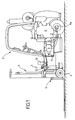
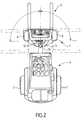
- a self-propelled carriage with an articulated frame comprises a part 1 chassis front and 2 rear chassis hinged to each other around a substantially vertical axis 3, so as to allow pivoting of the part before 1 relative to the rear portion 2 at an angle up to 90 °, to right or left.
- the front portion 1 of the chassis is provided with wheels 4 of fixed direction and free in rotation and supports lifting means 5, for example a telescopic mast equipped forks or equivalent gripping means.
- the rear part 2 of the chassis carries the driver's cabin, a motor 6 to internal combustion and two driving wheels 7 of fixed direction intended to be driven by the driving force produced by the internal combustion engine 6.
- the rear wheels 7 of the truck can be provided with engines hydraulic or geared motors 8a, 8b.
- the hydraulic motor or geared motor 8a of the left rear wheel is driven by a hydrostatic pump 9, while the motor gearbox or hydraulic motor 8b of the right rear wheel is driven by the hydrostatic pump 10.
- a hydraulic pump 11 is provided for actuating the means of lifting with corresponding cylinders and for actuating the direction of the carriage.
- the pumps 9, 10 and 11 are driven simultaneously by the internal combustion engine 6, and this automatically from the start of the engine 6 with internal combustion.
- the pumps 9 and 10 are connected to a set 12 intended to modify the driving of the hydraulic motors 8a, 8b of the wheels 7 by the pumps hydrostatic 9 and 10 depending on the steering angle of the truck.
- the turning of the front part 1 of the carriage relative to the rear part 2 can be obtained by a hydraulic motor 13 of direction driving a pinion acting on a ring gear secured to the front portion of the frame.
- a hydraulic motor 13 of direction driving a pinion acting on a ring gear secured to the front portion of the frame.
- other steering means may be used without departing from the scope of this invention, for example one or more steering cylinders.
- the characteristic curve of the ratio between the speed inside the turn and the wheel speed outside the turn depending on the steering angle of the front part of the carriage relative to the rear part of the carriage is shown in the range 0 to 90 °.
- the speed of rear wheels 7 is identical, which corresponds to a ratio between the wheel speed inside the turn and the outside wheel speed at the turn equal to 1.
- the ratio between the wheel speed inside the turn and the outside wheel speed at the turn is equal to 0.52, that is to say that the rear wheel 7 inside the turn, for example the left rear wheel, rotates at a speed equal to the product by 0.52 of the speed of the outer wheel at turn, for example the right rear wheel, so that the center A instantaneous of rotation is at the intersection of the axles of the front and rear axles.
- the center A instantaneous rotation moves on the axle of the rear axle until positioned in the center of the rear left wheel 7, which corresponds to a zero speed of rotation of the left rear wheel 7.
- the left rear wheel is stationary for a steering angle approximately 73 °, and the carriage pivots in this steering position around this left rear wheel.
- the rear wheel left is driven in the opposite direction of the right rear wheel 7 at a speed twice lower, which corresponds to a negative algebraic ratio of -0.5.
- the curve in Figure 3 is given for information only, and depends on dimensional characteristics of the carriage, in particular the distance between the axis passing through the centers of the front wheels 4 and the pivot axis 3; distance between the axis passing through the centers of the rear wheels 7 and the axis 3 of pivoting, and the geometric position of the rear wheels in relation to the median longitudinal axis of the trolley or the rear track of the trolley in the case of a symmetrical carriage compared to this longitudinal median axis.
- the curve could also be extended to steering angles greater than 90 °, in particular up to the steering angle corresponding to a position of the instantaneous center of rotation in the center of the rear axle or in the middle of segment joining the centers of the rear wheels 7.
- a curve giving the ratio between the speed of moving the truck for a given steering angle and the speed of displacement of the carriage in a straight line is represented according to the angle of steering of the truck, over the range of 0 to 90 °.
- the speed of movement of the truck for a given steering angle is equal to the half-sum of the inside wheel speed at the turn and the speed of outer wheel at the turn depending on the steering angle of the front part of the carriage relative to the rear part of the carriage.
- the speed of movement of the trolley for a given steering angle can therefore be calculated according to the wheel speed outside the turn from the curve of FIG. 3; and Figure 4 can therefore be inferred point by point from Figure 3.
- the speed of rear wheels 7 is identical, which corresponds to a ratio between the wheel speed inside the turn and the outside wheel speed at the turn equal to 1; and to a report between the travel speed of the truck for a zero steering angle and the speed moving the carriage in a straight line defined as 1.
- the ratio between the wheel speed inside the turn and the outside wheel speed at the turn is equal to 0.52, that is to say that the rear wheel 7 inside the turn, for example the left rear wheel, rotates at a speed equal to the product by 0.52 of the speed of the outer wheel at turn ; and at a ratio between the speed of movement of the carriage for an angle of 40 ° deflection and the speed of travel of the truck in a calculable straight line as equal to 0.76.
- the center A instantaneous rotation moves on the axle of the rear axle until positioned in the center of the rear left wheel 7, which corresponds to a zero speed of rotation of the left rear wheel 7; and a ratio between the speed of movement of the carriage for a steering angle of 73 ° and the traveling speed of the straight-line carriage calculable as equal to 0.5.
- the rear wheel left is driven in the opposite direction of the right rear wheel 7 at a speed twice lower, which corresponds to a negative algebraic ratio of -0.5; and to a report between the truck traveling speed for a 90 ° steering angle and the carriage speed in straight line calculable as equal to 0.25.
- the device according to the invention comprises, in a manner known per se, a valve AL to reduce the pilot pressure to allow a slow approach ("Inching" for specialists) of the truck, even with a motor maximum.
- This slow approach valve AL of a type known per se is actuated by preferably by a pedal or a slow approach lever.
- the device also comprises two cams concentric with the axis of pivoting 3: a first cam 14a for controlling the left rear wheel 7a and a second cam 14b for controlling the right rear wheel 7b.
- the cam 14a acts simultaneously on a pressure reducing valve 15 a driving the hydrostatic pump 9, and an electromechanical contactor 16a capable of reversing the flow rate of the hydrostatic pump 9 at speed zero drive of the left rear wheel 7a, in accordance with the curve of the figure 3.
- the second cam 14b controls the valve 15b of reduction of the pilot pressure of the hydrostatic pump 10 and triggers the electromechanical contactor 16b reversing the flow direction of the pump hydrostatic 10.
- the cams 14a and 14b are symmetrical to one another with respect to a plane median passing through the longitudinal axis 3.
- the pressures output valves 15a and 15b are identical and preferably equal to the pressure input, so as to rotate the two rear wheels 7a and 7b at the same speed.
- the corresponding piloting pressure the inner wheel at the turn is reduced in accordance with the curve of Figure 3, while the output pressure of the other control valve of the other pump hydrostatic remains equal to the inlet pressure.
- a hydrostatic pump 9 or 10 is used.
- inclined plate whose modification of the inclination makes it possible to vary the delivered flow by the pump until canceling it. Inversion of the tilt of the pump tray allows to obtain a flow in opposite direction of the previous flow.
- the invention is applicable to any hydrostatic flow pump variable, whether or not inclined plateau.
Landscapes
- Engineering & Computer Science (AREA)
- Transportation (AREA)
- Mechanical Engineering (AREA)
- Structural Engineering (AREA)
- General Engineering & Computer Science (AREA)
- Chemical & Material Sciences (AREA)
- Combustion & Propulsion (AREA)
- Life Sciences & Earth Sciences (AREA)
- Geology (AREA)
- Civil Engineering (AREA)
- Physics & Mathematics (AREA)
- Fluid Mechanics (AREA)
- Automation & Control Theory (AREA)
- Non-Deflectable Wheels, Steering Of Trailers, Or Other Steering (AREA)
- Control Of Fluid Gearings (AREA)
Applications Claiming Priority (2)
| Application Number | Priority Date | Filing Date | Title |
|---|---|---|---|
| FR0206413 | 2002-05-27 | ||
| FR0206413A FR2840045B1 (fr) | 2002-05-27 | 2002-05-27 | Dispositif de transmission hydrostatique et chariot articule correspondant |
Publications (3)
| Publication Number | Publication Date |
|---|---|
| EP1366970A2 true EP1366970A2 (de) | 2003-12-03 |
| EP1366970A3 EP1366970A3 (de) | 2006-05-03 |
| EP1366970B1 EP1366970B1 (de) | 2013-01-30 |
Family
ID=29415087
Family Applications (1)
| Application Number | Title | Priority Date | Filing Date |
|---|---|---|---|
| EP03291207A Expired - Lifetime EP1366970B1 (de) | 2002-05-27 | 2003-05-22 | Hydrostatische Antriebsvorrichtung für Gelenktransportwagen |
Country Status (2)
| Country | Link |
|---|---|
| EP (1) | EP1366970B1 (de) |
| FR (1) | FR2840045B1 (de) |
Cited By (1)
| Publication number | Priority date | Publication date | Assignee | Title |
|---|---|---|---|---|
| EP1870375A3 (de) * | 2006-06-20 | 2008-05-21 | J.C. Bamford Excavators Limited | Lademaschine |
Families Citing this family (8)
| Publication number | Priority date | Publication date | Assignee | Title |
|---|---|---|---|---|
| CN101767514A (zh) * | 2010-03-22 | 2010-07-07 | 无锡汇丰机器有限公司 | 一种叉车车轿 |
| CN101774333A (zh) * | 2010-03-23 | 2010-07-14 | 无锡汇丰机器有限公司 | 一种高性能叉车车轿 |
| CN104554491A (zh) * | 2013-10-12 | 2015-04-29 | 宁波如意股份有限公司 | 四向行驶叉车驾驶室 |
| WO2018049475A1 (en) | 2016-09-15 | 2018-03-22 | Terex Australia Pty Ltd | Crane counterweight and suspension |
| CN110526172A (zh) * | 2019-09-25 | 2019-12-03 | 合肥搬易通科技发展有限公司 | 一种四支点窄巷道铰接式叉车 |
| CN110589722A (zh) * | 2019-09-25 | 2019-12-20 | 合肥搬易通科技发展有限公司 | 一种三支点多转向窄巷道铰接式叉车 |
| CN110626995A (zh) * | 2019-09-25 | 2019-12-31 | 合肥搬易通科技发展有限公司 | 一种四支点多转向窄巷道铰接式叉车 |
| CN110589718A (zh) * | 2019-09-25 | 2019-12-20 | 合肥搬易通科技发展有限公司 | 一种三支点窄巷道铰接式叉车 |
Family Cites Families (3)
| Publication number | Priority date | Publication date | Assignee | Title |
|---|---|---|---|---|
| GB1092281A (en) * | 1963-05-22 | 1967-11-22 | Ransomes Sims & Jefferies Ltd | Improvements in fork-lift reach trucks |
| GB1588716A (en) * | 1976-08-18 | 1981-04-29 | Bushell P | All-wheel-drive vehicle |
| EP1118581A1 (de) * | 1999-05-07 | 2001-07-25 | TCM Corporation | Hydraulisch angetriebener gabelhubwagen |
-
2002
- 2002-05-27 FR FR0206413A patent/FR2840045B1/fr not_active Expired - Fee Related
-
2003
- 2003-05-22 EP EP03291207A patent/EP1366970B1/de not_active Expired - Lifetime
Cited By (2)
| Publication number | Priority date | Publication date | Assignee | Title |
|---|---|---|---|---|
| EP1870375A3 (de) * | 2006-06-20 | 2008-05-21 | J.C. Bamford Excavators Limited | Lademaschine |
| US7971889B2 (en) | 2006-06-20 | 2011-07-05 | J. C. Bamford Excavators Limited | Loading machine |
Also Published As
| Publication number | Publication date |
|---|---|
| FR2840045A1 (fr) | 2003-11-28 |
| EP1366970B1 (de) | 2013-01-30 |
| EP1366970A3 (de) | 2006-05-03 |
| FR2840045B1 (fr) | 2004-11-12 |
Similar Documents
| Publication | Publication Date | Title |
|---|---|---|
| EP3046780B1 (de) | Anordnung mit einem fahrgestell für ein fahrzeug mit variabler spur, z. b. ein landwirtschaftliches fahrzeug wie einen sprüher oder ein hohes reinigungsfahrzeug | |
| FR2918433A1 (fr) | Organe de transmission destine a etre interpose entre un arbre moteur et deux demi-arbres et permettant de piloter en continu la repartition du couple transmis aux demi-arbres | |
| JP4125435B2 (ja) | 走行車両 | |
| EP1366970B1 (de) | Hydrostatische Antriebsvorrichtung für Gelenktransportwagen | |
| FR2785958A1 (fr) | Dispositif d'entrainement hydraulique pour un vehicule industriel a quatre roues motrices et vehicule industriel a quatre roues motrices comportant le dispositif | |
| WO2000068134A1 (fr) | Leve-palette hydraulique | |
| FR2636031A1 (fr) | Direction toutes-roues pour vehicules automobiles | |
| EP1348668B1 (de) | Dreirädriger Hubwagen mit verstellbarem Arm | |
| EP0493206B1 (de) | Fahrzeug mit Mischlenkung | |
| FR2822123A1 (fr) | Essieu de vehicule | |
| FR2707932A1 (fr) | Structure de commande de déplacement d'un tracteur de tondeuse. | |
| FR2473444A1 (fr) | Vehicule sans conducteur a came de commande de vitesse de convoyeur utilisant ce vehicule | |
| EP2459399B1 (de) | Fahrzeug mit drei nicht lenkenden achsen | |
| BE1008762A6 (fr) | Appareil de levage et de manoeuvre d'un vehicule automobile et vehicule autmobile equipe d'un tel dispositif. | |
| FR2851219A1 (fr) | Procede de reduction du diametre de braquage d'un vehicule automobile et vehicule automobile | |
| FR2604680A1 (fr) | Vehicule automobile avec direction de roues avant et direction de roues arriere, notamment une direction des quatre roues | |
| EP1169210B1 (de) | Fahrzeug mit geführter, variabler pendelung | |
| EP2570331B1 (de) | Lenkvorrichtung eines selbstfahrenden Fahrzeugs | |
| JP4390960B2 (ja) | クローラ走行車 | |
| FR2529526A1 (fr) | Bateau mu par l'energie disponible sur un vehicule terrestre | |
| FR2808575A1 (fr) | Differentiel pour vehicule automobile | |
| FR2692220A1 (fr) | Véhicule routier à disposition de roues perfectionnée. | |
| JP2588051Y2 (ja) | 大型フォークリフトの走行駆動装置 | |
| JP4605649B2 (ja) | 草刈り機 | |
| BE565537A (de) |
Legal Events
| Date | Code | Title | Description |
|---|---|---|---|
| PUAI | Public reference made under article 153(3) epc to a published international application that has entered the european phase |
Free format text: ORIGINAL CODE: 0009012 |
|
| AK | Designated contracting states |
Kind code of ref document: A2 Designated state(s): AT BE BG CH CY CZ DE DK EE ES FI FR GB GR HU IE IT LI LU MC NL PT RO SE SI SK TR |
|
| AX | Request for extension of the european patent |
Extension state: AL LT LV MK |
|
| 17P | Request for examination filed |
Effective date: 20040325 |
|
| PUAL | Search report despatched |
Free format text: ORIGINAL CODE: 0009013 |
|
| AK | Designated contracting states |
Kind code of ref document: A3 Designated state(s): AT BE BG CH CY CZ DE DK EE ES FI FR GB GR HU IE IT LI LU MC NL PT RO SE SI SK TR |
|
| AX | Request for extension of the european patent |
Extension state: AL LT LV MK |
|
| 17Q | First examination report despatched |
Effective date: 20061017 |
|
| AKX | Designation fees paid |
Designated state(s): AT BE BG CH CY CZ DE DK EE ES FI FR GB GR HU IE IT LI LU MC NL PT RO SE SI SK TR |
|
| GRAP | Despatch of communication of intention to grant a patent |
Free format text: ORIGINAL CODE: EPIDOSNIGR1 |
|
| GRAS | Grant fee paid |
Free format text: ORIGINAL CODE: EPIDOSNIGR3 |
|
| GRAA | (expected) grant |
Free format text: ORIGINAL CODE: 0009210 |
|
| AK | Designated contracting states |
Kind code of ref document: B1 Designated state(s): AT BE BG CH CY CZ DE DK EE ES FI FR GB GR HU IE IT LI LU MC NL PT RO SE SI SK TR |
|
| REG | Reference to a national code |
Ref country code: GB Ref legal event code: FG4D Free format text: NOT ENGLISH |
|
| REG | Reference to a national code |
Ref country code: CH Ref legal event code: EP |
|
| REG | Reference to a national code |
Ref country code: CH Ref legal event code: EP Ref country code: AT Ref legal event code: REF Ref document number: 595656 Country of ref document: AT Kind code of ref document: T Effective date: 20130215 |
|
| REG | Reference to a national code |
Ref country code: IE Ref legal event code: FG4D Free format text: LANGUAGE OF EP DOCUMENT: FRENCH |
|
| REG | Reference to a national code |
Ref country code: DE Ref legal event code: R096 Ref document number: 60343211 Country of ref document: DE Effective date: 20130328 |
|
| REG | Reference to a national code |
Ref country code: AT Ref legal event code: MK05 Ref document number: 595656 Country of ref document: AT Kind code of ref document: T Effective date: 20130130 |
|
| REG | Reference to a national code |
Ref country code: NL Ref legal event code: VDEP Effective date: 20130130 |
|
| PG25 | Lapsed in a contracting state [announced via postgrant information from national office to epo] |
Ref country code: AT Free format text: LAPSE BECAUSE OF FAILURE TO SUBMIT A TRANSLATION OF THE DESCRIPTION OR TO PAY THE FEE WITHIN THE PRESCRIBED TIME-LIMIT Effective date: 20130130 Ref country code: SE Free format text: LAPSE BECAUSE OF FAILURE TO SUBMIT A TRANSLATION OF THE DESCRIPTION OR TO PAY THE FEE WITHIN THE PRESCRIBED TIME-LIMIT Effective date: 20130130 Ref country code: ES Free format text: LAPSE BECAUSE OF FAILURE TO SUBMIT A TRANSLATION OF THE DESCRIPTION OR TO PAY THE FEE WITHIN THE PRESCRIBED TIME-LIMIT Effective date: 20130511 Ref country code: CY Free format text: LAPSE BECAUSE OF FAILURE TO SUBMIT A TRANSLATION OF THE DESCRIPTION OR TO PAY THE FEE WITHIN THE PRESCRIBED TIME-LIMIT Effective date: 20130130 Ref country code: BG Free format text: LAPSE BECAUSE OF FAILURE TO SUBMIT A TRANSLATION OF THE DESCRIPTION OR TO PAY THE FEE WITHIN THE PRESCRIBED TIME-LIMIT Effective date: 20130430 |
|
| PG25 | Lapsed in a contracting state [announced via postgrant information from national office to epo] |
Ref country code: GR Free format text: LAPSE BECAUSE OF FAILURE TO SUBMIT A TRANSLATION OF THE DESCRIPTION OR TO PAY THE FEE WITHIN THE PRESCRIBED TIME-LIMIT Effective date: 20130501 Ref country code: FI Free format text: LAPSE BECAUSE OF FAILURE TO SUBMIT A TRANSLATION OF THE DESCRIPTION OR TO PAY THE FEE WITHIN THE PRESCRIBED TIME-LIMIT Effective date: 20130130 Ref country code: NL Free format text: LAPSE BECAUSE OF FAILURE TO SUBMIT A TRANSLATION OF THE DESCRIPTION OR TO PAY THE FEE WITHIN THE PRESCRIBED TIME-LIMIT Effective date: 20130130 Ref country code: PT Free format text: LAPSE BECAUSE OF FAILURE TO SUBMIT A TRANSLATION OF THE DESCRIPTION OR TO PAY THE FEE WITHIN THE PRESCRIBED TIME-LIMIT Effective date: 20130530 Ref country code: SI Free format text: LAPSE BECAUSE OF FAILURE TO SUBMIT A TRANSLATION OF THE DESCRIPTION OR TO PAY THE FEE WITHIN THE PRESCRIBED TIME-LIMIT Effective date: 20130130 |
|
| PG25 | Lapsed in a contracting state [announced via postgrant information from national office to epo] |
Ref country code: CZ Free format text: LAPSE BECAUSE OF FAILURE TO SUBMIT A TRANSLATION OF THE DESCRIPTION OR TO PAY THE FEE WITHIN THE PRESCRIBED TIME-LIMIT Effective date: 20130130 Ref country code: EE Free format text: LAPSE BECAUSE OF FAILURE TO SUBMIT A TRANSLATION OF THE DESCRIPTION OR TO PAY THE FEE WITHIN THE PRESCRIBED TIME-LIMIT Effective date: 20130130 Ref country code: SK Free format text: LAPSE BECAUSE OF FAILURE TO SUBMIT A TRANSLATION OF THE DESCRIPTION OR TO PAY THE FEE WITHIN THE PRESCRIBED TIME-LIMIT Effective date: 20130130 Ref country code: DK Free format text: LAPSE BECAUSE OF FAILURE TO SUBMIT A TRANSLATION OF THE DESCRIPTION OR TO PAY THE FEE WITHIN THE PRESCRIBED TIME-LIMIT Effective date: 20130130 Ref country code: RO Free format text: LAPSE BECAUSE OF FAILURE TO SUBMIT A TRANSLATION OF THE DESCRIPTION OR TO PAY THE FEE WITHIN THE PRESCRIBED TIME-LIMIT Effective date: 20130130 |
|
| BERE | Be: lapsed |
Owner name: MANITOU BF Effective date: 20130531 |
|
| REG | Reference to a national code |
Ref country code: DE Ref legal event code: R119 Ref document number: 60343211 Country of ref document: DE |
|
| PLBE | No opposition filed within time limit |
Free format text: ORIGINAL CODE: 0009261 |
|
| STAA | Information on the status of an ep patent application or granted ep patent |
Free format text: STATUS: NO OPPOSITION FILED WITHIN TIME LIMIT |
|
| PG25 | Lapsed in a contracting state [announced via postgrant information from national office to epo] |
Ref country code: IT Free format text: LAPSE BECAUSE OF FAILURE TO SUBMIT A TRANSLATION OF THE DESCRIPTION OR TO PAY THE FEE WITHIN THE PRESCRIBED TIME-LIMIT Effective date: 20130130 Ref country code: MC Free format text: LAPSE BECAUSE OF FAILURE TO SUBMIT A TRANSLATION OF THE DESCRIPTION OR TO PAY THE FEE WITHIN THE PRESCRIBED TIME-LIMIT Effective date: 20130130 |
|
| REG | Reference to a national code |
Ref country code: CH Ref legal event code: PL |
|
| 26N | No opposition filed |
Effective date: 20131031 |
|
| PG25 | Lapsed in a contracting state [announced via postgrant information from national office to epo] |
Ref country code: DE Free format text: LAPSE BECAUSE OF NON-PAYMENT OF DUE FEES Effective date: 20131203 Ref country code: LI Free format text: LAPSE BECAUSE OF NON-PAYMENT OF DUE FEES Effective date: 20130531 Ref country code: CH Free format text: LAPSE BECAUSE OF NON-PAYMENT OF DUE FEES Effective date: 20130531 |
|
| REG | Reference to a national code |
Ref country code: DE Ref legal event code: R097 Ref document number: 60343211 Country of ref document: DE Effective date: 20131031 |
|
| REG | Reference to a national code |
Ref country code: IE Ref legal event code: MM4A |
|
| PG25 | Lapsed in a contracting state [announced via postgrant information from national office to epo] |
Ref country code: BE Free format text: LAPSE BECAUSE OF NON-PAYMENT OF DUE FEES Effective date: 20130531 |
|
| REG | Reference to a national code |
Ref country code: DE Ref legal event code: R119 Ref document number: 60343211 Country of ref document: DE Effective date: 20131203 |
|
| PG25 | Lapsed in a contracting state [announced via postgrant information from national office to epo] |
Ref country code: IE Free format text: LAPSE BECAUSE OF NON-PAYMENT OF DUE FEES Effective date: 20130522 |
|
| PG25 | Lapsed in a contracting state [announced via postgrant information from national office to epo] |
Ref country code: TR Free format text: LAPSE BECAUSE OF FAILURE TO SUBMIT A TRANSLATION OF THE DESCRIPTION OR TO PAY THE FEE WITHIN THE PRESCRIBED TIME-LIMIT Effective date: 20130130 |
|
| PG25 | Lapsed in a contracting state [announced via postgrant information from national office to epo] |
Ref country code: HU Free format text: LAPSE BECAUSE OF FAILURE TO SUBMIT A TRANSLATION OF THE DESCRIPTION OR TO PAY THE FEE WITHIN THE PRESCRIBED TIME-LIMIT; INVALID AB INITIO Effective date: 20030522 Ref country code: LU Free format text: LAPSE BECAUSE OF NON-PAYMENT OF DUE FEES Effective date: 20130522 |
|
| REG | Reference to a national code |
Ref country code: FR Ref legal event code: PLFP Year of fee payment: 14 |
|
| REG | Reference to a national code |
Ref country code: FR Ref legal event code: PLFP Year of fee payment: 15 |
|
| REG | Reference to a national code |
Ref country code: FR Ref legal event code: PLFP Year of fee payment: 16 |
|
| PGFP | Annual fee paid to national office [announced via postgrant information from national office to epo] |
Ref country code: FR Payment date: 20190522 Year of fee payment: 17 |
|
| PGFP | Annual fee paid to national office [announced via postgrant information from national office to epo] |
Ref country code: GB Payment date: 20190521 Year of fee payment: 17 |
|
| GBPC | Gb: european patent ceased through non-payment of renewal fee |
Effective date: 20200522 |
|
| PG25 | Lapsed in a contracting state [announced via postgrant information from national office to epo] |
Ref country code: GB Free format text: LAPSE BECAUSE OF NON-PAYMENT OF DUE FEES Effective date: 20200522 Ref country code: FR Free format text: LAPSE BECAUSE OF NON-PAYMENT OF DUE FEES Effective date: 20200531 |