EP1367149A1 - Vorrichtung zur Herstellung von Fluorgas - Google Patents
Vorrichtung zur Herstellung von Fluorgas Download PDFInfo
- Publication number
- EP1367149A1 EP1367149A1 EP03012046A EP03012046A EP1367149A1 EP 1367149 A1 EP1367149 A1 EP 1367149A1 EP 03012046 A EP03012046 A EP 03012046A EP 03012046 A EP03012046 A EP 03012046A EP 1367149 A1 EP1367149 A1 EP 1367149A1
- Authority
- EP
- European Patent Office
- Prior art keywords
- gas
- fluorine gas
- pressure
- level
- electrolytic cell
- Prior art date
- Legal status (The legal status is an assumption and is not a legal conclusion. Google has not performed a legal analysis and makes no representation as to the accuracy of the status listed.)
- Granted
Links
Images


Classifications
-
- C—CHEMISTRY; METALLURGY
- C25—ELECTROLYTIC OR ELECTROPHORETIC PROCESSES; APPARATUS THEREFOR
- C25B—ELECTROLYTIC OR ELECTROPHORETIC PROCESSES FOR THE PRODUCTION OF COMPOUNDS OR NON-METALS; APPARATUS THEREFOR
- C25B15/00—Operating or servicing cells
-
- C—CHEMISTRY; METALLURGY
- C25—ELECTROLYTIC OR ELECTROPHORETIC PROCESSES; APPARATUS THEREFOR
- C25B—ELECTROLYTIC OR ELECTROPHORETIC PROCESSES FOR THE PRODUCTION OF COMPOUNDS OR NON-METALS; APPARATUS THEREFOR
- C25B1/00—Electrolytic production of inorganic compounds or non-metals
- C25B1/01—Products
- C25B1/24—Halogens or compounds thereof
- C25B1/245—Fluorine; Compounds thereof
-
- C—CHEMISTRY; METALLURGY
- C25—ELECTROLYTIC OR ELECTROPHORETIC PROCESSES; APPARATUS THEREFOR
- C25B—ELECTROLYTIC OR ELECTROPHORETIC PROCESSES FOR THE PRODUCTION OF COMPOUNDS OR NON-METALS; APPARATUS THEREFOR
- C25B15/00—Operating or servicing cells
- C25B15/02—Process control or regulation
-
- C—CHEMISTRY; METALLURGY
- C25—ELECTROLYTIC OR ELECTROPHORETIC PROCESSES; APPARATUS THEREFOR
- C25B—ELECTROLYTIC OR ELECTROPHORETIC PROCESSES FOR THE PRODUCTION OF COMPOUNDS OR NON-METALS; APPARATUS THEREFOR
- C25B15/00—Operating or servicing cells
- C25B15/02—Process control or regulation
- C25B15/023—Measuring, analysing or testing during electrolytic production
- C25B15/025—Measuring, analysing or testing during electrolytic production of electrolyte parameters
Definitions
- the present invention relates to an on-site type fluorine gas generator.
- Fluorine gas is one of the key gases essential in the field of semiconductor production, for instance. While it is used as such in certain instances, the demand for nitrogen trifluoride gas (hereinafter referred to as "NF 8 gas”) and like gases synthesized based on fluorine gas and intended for use as cleaning gases or dry etching gases in semiconductor manufacturing apparatus has been rapidly increasing.
- NF 8 gas nitrogen trifluoride gas
- NeF gas neon fluoride gas
- ArF gas argon fluoride gas
- KrF gas krypton fluoride gas
- the fluorine gas or NF 8 gas for use in the manufacture of semiconductors and the like is required to be highly pure with the impurity content as low as possible.
- necessary amounts of fluorine gas are taken out of gas cylinders filled with nitrogen gas. It thus becomes very important to secure sites for storing such cylinders, store the gas safely, maintain the purity of the gas, and manage for such purposes.
- NF 3 gas for which the demand has been increasing lately, the demand tends to exceed the supply, hence there arises a problem that certain amounts of the gas should be in stock.
- to have a fluorine gas generator or producer of the on-demand and on-site type at the site of use thereof is preferred to handling high-pressure fluorine gas cylinders.
- the electrolytic cell body 201 is generally made of Ni, Monel, carbon steel or the like. At the bottom of the electrolytic cell body 201, a bottom plate 212 made of polytetrafluoroethylene or the like is disposed for preventing the hydrogen gas and fluorine gas generated from being mixed with each other.
- the electrolytic cell body 201 is filled with an electrolytic bath 202, namely a potassium fluoride-hydrogen fluoride system (hereinafter referred to as "KF-HF system”) in the form of a mixed molten salt.
- KF-HF system potassium fluoride-hydrogen fluoride system
- the cell or bath is divided into an anode chamber 210 and a cathode chamber 211 by means of a skirt 209 made of Monel or the like.
- a voltage between a carbon or nickel (hereinafter referred to as "Ni") anode 203 contained in the anode chamber and a Ni cathode 204 contained in the cathode chamber 211 electrolysis occurs and fluorine gas is produced.
- the fluorine gas generated is discharged through a product line 208, and the hydrogen gas formed on the cathode side is discharged through a hydrogen gas discharge line 207.
- CF 4 gas carbon tetrafluoride
- HF gas hydrogen fluoride gas
- a fluorine gas generator for generating highly pure fluorine gas by electrolyzing an electrolytic bath comprising hydrogen fluoride in the form of a molten mixed salt
- generator comprises, according to Claim 1, an electrolytic cell divided, by a partition wall, into an anode chamber in which an anode is disposed and a cathode chamber in which a cathode is disposed, pressure maintenance means for maintaining the electrolytic cell inside at atmospheric pressure, and liquid level sensing means capable of sensing the levels of the electrolytic bath in the anode chamber and in the cathode chamber, respectively, at three or more level stages.
- the pressure maintenance means in the fluorine gas generator according to Claim 1 comprises automatic valves operated (opened/closed) in association with pressure gauges connected to the anode chamber and cathode chamber, respectively, and automatic valves operated in association with the level sensing means disposed in the anode chamber and cathode chamber, respectively.
- This constitution makes it possible to control the electrolytic cell inside pressure in an easy and reliable manner.
- the operation of the automatic valves in association with the level sensing means makes it possible to automatically control the level of the electrolytic bath.
- the automatic valves which are one of the constituent elements of the pressure maintenance means for maintaining the electrolytic cell inside pressure at atmospheric pressure in the fluorine gas generator according to Claim 2, are opened to discharge the electrolytic cell inside gas when the electrolytic cell inside pressure becomes higher than atmospheric pressure.
- This constitution makes it possible to maintain the electrolytic cell inside, in particular the cathode chamber inside, always at atmospheric pressure. As a result, the level of the electrolytic bath in the electrolytic cell can be always maintained in a stable condition.
- a compressor and/or a vacuum generator is disposed behind the automatic valves operated in association with the pressure gauges in the fluorine gas generator according to any one of Claims 1 to 3 to maintain the valves operated in association with the pressure gauges in a reduced pressure state.
- the gas discharge lines on the downstream side of the automatic valves operated in association with the pressure gauges are placed in a reduced pressure state.
- the gas discharged from the cathode chamber passes through the valve operated in association with the relevant pressure gauge in a more reliable manner.
- the level sensing means in the fluorine gas generator according to Claim 1 each comprises at least three level sensors capable of sensing different liquid levels of the electrolytic bath.
- This constitution makes it possible to detect the electrolytic bath liquid levels in the electrolytic cell at three or more stages and, therefore, detect even small changes in liquid level. And, it becomes possible to operate each valve on each gas line connected with the electrolytic cell in response to the signal from the relevant level sensor to allow gas inflow for pressurization or reduce the pressure to raise the liquid level. Therefore, automatic operation becomes possible while maintaining each liquid level at a constant level without discontinuation of electrolysis as resulting from electrolytic bath level control (on/off control), as described in JP Kohyo H09-505853, EP0728228B1, EP0852267B1, EP0965661B1, and USP5688384.
- the fluorine gas generator has pressure gages capable of detecting the electrolytic cell inside pressures in addition to the level sensing means.
- This constitution makes it possible to more precisely control the liquid level fluctuations due to the differential pressure-caused ascending or descending of the electrolytic bath and prevent the choking of filters or the like disposed in the downstream piping and lines due to splashing of the electrolytic bath, for instance.
- This control makes it possible to ensure the operation in a safe and stable manner.
- a rare gas or nitrogen gas is fed to the cathode chamber or/and anode chamber through the automatic valves operated in association with the level sensing means in the fluorine gas generator according to Claim 1 or 2.
- the gas generated when diluted with a rare gas such as neon gas (Ne gas), argon gas (Ar gas) or krypton gas (Kr gas), can be used, in the form of a mixed gas with an arbitrary mixing ratio, as the excimer laser oscillation gas in patterning integrated semiconductor circuits.
- a rare gas such as neon gas (Ne gas), argon gas (Ar gas) or krypton gas (Kr gas)
- 1 stands for an electrolytic cell
- 2 for an electrolytic bath 3 for an anode chamber
- 4 for a cathode chamber 5 for first level sensing means
- 6 for second level sensing means 7 and 8 each for a pressure gauge
- 9 and 10 each for an automatic valve
- 11 for a thermometer 12 for temperature control means
- 13 for a heater 14 for an HF adsorber
- 15 for an HF absorber 16 for a partition wall, 17 for an upper covering, 18 and 19 each for a gas line, 20, 21 each for a purge gas inlet/outlet, 22 and 23 each for a gas outlet port
- 24 for an HF feed line 25 for an HF introduction port
- 26 for a vacuum generator 27 and 28 each for a gas line, 29 and 30 each for a pressure gauge
- 31 to 34 each for an automatic valve
- 35 to 38 each for a manual valve
- 39 to 41 each for a flowmeter 42 for a compressor unit
- S1 to S5 each for a level sensor.
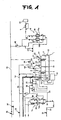
- Fig. 1 is a schematic representation of the principal part of a fluorine gas generator according to the invention.
- Fig. 1,1 is an electrolytic cell
- 2 is an electrolytic bath consisting of a fused or molten KF-HF system-based salt
- 3 is an anode chamber
- 4 is a cathode chamber
- 5 is first level sensing means for sensing the level of the electrolytic bath 2 in the anode chamber
- 6 is second level sensing means for sensing the liquid level in the cathode chamber 4 at 5 level stages.
- 7 is a pressure gauge for measuring the pressure in the anode chamber
- 8 is a pressure gauge for measuring the pressure in the cathode chamber 4.
- 9 and 10 are automatic valves operated in association with the pressures measured by the pressure gauges 7 and 8.
- 11 is a thermometer for measuring the temperature of the electrolytic bath 2
- 12 is temperature control means for controlling a heater 13 disposed around the side faces and bottom of the electrolytic cell 1 according to the signals from the thermometer 11.
- 14 is an adsorber for adsorbing HF gas in the hydrogen-HF mixed gas discharged from the cathode chamber 4
- 15 is an HF absorber packed with NaF, for instance, for adsorbing HF gas in the F 2 -HF mixed gas discharged from the anode chamber 3 to thereby discharge highly pure fluorine gas alone.
- the electrolytic cell 1 is made of a metal such as Ni, Monel, pure iron or stainless steel.
- the electrolytic cell 1 is divided into the anode chamber 3 and cathode chamber 4 by means of a partition wall 16 made of Ni or Monel.
- the anode is preferably a block-shaped one prepared from a graphite molding by processing to an appropriate shape.
- the cathode is preferably made of Ni or iron.
- the upper covering 17 of the electrolytic cell 1 has inlets/outlets 20, 21 for a purge gas from gas lines 18, 19, which are constituent elements of the pressure maintenance means for maintaining the anode chamber 3 inside and cathode chamber 4 inside at atmospheric pressure, an outlet port 22 for the fluorine gas generated in the anode chamber 3, and an outlet port 23 for the hydrogen gas generated in the cathode chamber 4.
- These outlet ports 22, 23 each comprises a bent pipe made of an anticorrosive material resistant to fluorine gas, such as Hastelloy, for preventing splashes from the anode chamber 3 and cathode chamber 4 from entering the gas lines.
- the upper covering 17 is also provided with an inlet 25 for introducing HF from an HF feeding line 24 when the level of the electrolytic bath 2 descends, first level sensing means 5, second level sensing means 6 for sensing the levels in the anode chamber 3 and cathode chamber 4, respectively, and pressure gauges 7 and 8.
- the electrolytic cell 1 is further provided with temperature adjusting means for heating the inside of the electrolytic cell 1.
- the temperature adjusting means is constituted of the heater 13 disposed around the electrolytic cell 1 in close contact therewith, temperature control means 12 connected with the heater 13 and capable of conventional PID control, and a thermometer 11, for example a thermocouple, disposed in either one of the anode chamber 3 and cathode chamber 4, and thus controls the temperature in the electrolytic cell 1. It is also possible to dispose a heat insulating material around the heater 13.
- the heater 13 may be of the ribbon type, nichrome wire type, or warm water type, for instance.
- the shape is not particularly restricted but preferably is such that the electrolytic cell is wholly surrounded.
- the first level sensing means 5 and second level sensing means 6 each is provided, for example, with five level sensors S1 to S5.
- the liquid level height of the electrolytic bath 2 can be detected stepwise by means of these five sensors S1 to S5.
- the pressure maintenance means for maintaining the inside of the anode chamber 3 and cathode chamber 4 at atmospheric pressure comprises automatic valves 9, 10 operated for passing or shutting a pressurizing gas from a gas cylinder in according to the results of pressure gauges 7, 8 for measuring the pressures in the anode chamber 3 and cathode chamber 4, respectively, automatic valves 31-34 operated according to the results of sensing of the liquid levels of the electrolytic bath 2 by the first level sensing means 5 and second level sensing means 6 to feed or discharge the gas to or from the anode chamber 3 or/and cathode chamber 4, respectively, manual valves 35-38 operated for passing or shutting the gas lines 18, 19, etc.
- This pressure maintenance means maintains the pressure in the anode chamber 3 and cathode chamber 4 at the atmospheric pressure level, whereby the pressure in the electrolytic cell 1 is maintained at the atmospheric pressure level and the level heights can be maintained in a stable condition during electrolysis. Therefore, the fluctuations in electrolysis conditions are small, hence the electrolysis can be carried out stably.
- the fluorine gas and hydrogen gas formed upon electrolysis are discharged, in a forced-out manner, from the electrolytic cell 1 through the outlets 22, 23.
- the pressure maintenance means maintains the anode chamber 3 inside and cathode chamber 4 inside at atmospheric pressure and thereby discharges the gases generated upon electrolysis from the electrolytic cell 1 and, at the same time, prevents the open air from coming into the electrolytic cell 1.
- the gas to be fed to the electrolytic cell 1 connected with the pressure maintenance means is not particularly restricted but may be any inert gas.
- nitrogen gas or at least one of rare gases such as Ar gas, Ne gas, Kr gas and Xe gas
- a mixed gas composed fluorine gas and such a rare gas can be easily obtained in an arbitrary mixing ratio.
- the mixed gas for example, as a radiation source for excimer laser oscillation in patterning integrated circuits in the field of semiconductor manufacture.
- the HF adsorber 14 for adsorbing HF gas in the hydrogen gas discharged from the cathode chamber 4 comprises a first adsorption column 14a and a second adsorption column 14b disposed in parallel. These first adsorption column 14a and second absorption column 14b may be operated simultaneously, or one of them alone may be operated.
- This adsorber 14 is preferably made of an anticorrosive material resistant to fluorine gas and HF, for example stainless steel, Monel, Ni, or a fluororesin. The inside thereof is filled with sodium fluoride or soda lime, for instance, which adsorbs HF passing therethrough and thereby eliminating HF from the hydrogen gas.
- This HF adsorber 14 is disposed on the downstream side of the automatic valve 10, which is one of the constituent elements of the pressure maintenance means.
- a vacuum generator 26 is disposed between this automatic valve 10 and the HF adsorber 14. This vacuum generator 26 serves to place the inside of the gas line 28 in a reduced pressure condition utilizing the ejector effect of the gas passing through the gas line 27.
- the gas line 28 can be placed in a reduced pressure state without using any oil, hence oil invasion into the gas line and electrolytic cell 1 can be avoided.
- the HF absorber 15 for removing HF in the fluorine gas discharged from the anode chamber 3 comprises a first absorption column 15a and a second absorption column 15b disposed in parallel. NaF is filled in the inside of each column and removes HF contained in the fluorine gas discharged.
- this HF absorber 15 is preferably made of an anticorrosive material resistant to fluorine gas and HF, for example stainless steel, Monel or Ni.
- the automatic valve 9 which is one the constituent elements of the pressure maintenance means.
- the gas generated from the anode chamber 3 is in a server environment where HF gas is formed simultaneously with fluorine gas and splashing of the electrolytic bath occurs. Particularly, in an environment where fluorine and HF occur in a mixed state, a strongly oxidative atmosphere is created.
- a condition in which HF-free fluorine gas alone occurs can be created and the valve can be operated without being affected by HF gas.
- the HF adsorber 14 and HF absorber 15 are provided with pressure gauges 30 and 29, respectively, whereby the choking in the inside can be detected upon occurrence thereof.
- the fluorine gas generator comprising such electrolytic cell 1 is preferably set up within a cabinet formed of one box body (not shown). This is because the on-demand, on-site use of the generator is facilitated thereby.
- the cabinet is preferably made of a material nonreactive with fluorine gas, for example such as metal as stainless steel or such a resin as polyvinyl chloride.
- storage means for example a buffer tank, is preferably disposed downstream from the side of high purity fluorine gas discharge. This makes it possible to supply fluorine gas at any time in case of necessity and in any required amount. According to this arrangement, a fluorine gas generator for the manufacture lines on the sites of semiconductor manufacture is provided.
- the inside of the electrolytic cell 1 is generally maintained at atmospheric pressure and the level of the electrolytic bath 2 in the anode chamber 3 is equal to that in the cathode chamber 4.
- the pressure within the electrolytic cell 1 fluctuates.
- the pressure gauges 7, 8 connected to the anode chamber 3 and cathode chamber 4, respectively measure the pressures and, according to the pressure fluctuations, the automatic valves 9, 10 are operated in association with the pressure gauges 7, 8 to make adjustments so that the pressure within the electrolytic cell 1 may be maintained at the atmospheric pressure level.
- the liquid level height of the electrolytic bath 2 is generally located at a position between the level sensors S2 and S4 among the five level sensors S1 to S5 in each of the first level sensing means 5 and second level sensing means 6.
- the automatic valve 31 and automatic valve 34 are closed.
- the automatic valve 31 and automatic valve 34 are opened and electrolysis is continued. If the level of the electrolytic bath 2 in the cathode chamber 2 still increases even after closure of the automatic valve 31 and automatic valve 34 and exceeds the level of the level sensor S1 the automatic valve 33 and automatic valve 32 are also closed and the electrolysis is discontinued.
- the automatic valve 32 Upon discontinuation of electrolysis, the automatic valve 32 is opened for a short period of time, and the fluorine gas in the anode chamber 3 is discharged through the fluorine gas outlet 23 on the upper covering 17 of the electrolytic cell 1. At the same time, the automatic valve 33 is also opened for a short period and a purge gas is introduced into the cathode chamber 4. When the level heights of the electrolytic bath 2 in the anode chamber 3 and that in the cathode chamber 4 become equal again, electrolysis is restarted.
- the pressure within the electrolytic cell is adjusted by means of the pressure gages 7, 8 for measuring the pressures within the electrolytic cell 1 inside and the automatic valves 9, 10 operated in association with those gauges, and the level height of the electrolytic bath 2 is controlled while maintaining the electrolytic cell 1 inside at atmospheric pressure, as described hereinabove.
- the inside of the electrolytic cell 1 is maintained at atmospheric pressure by means of the first level sensing means 5 and second level sensing means 6 disposed in the anode chamber 3 and cathode chamber 4, respectively, and the automatic valves 31-34 operated in association with those means.
- Such a two-stage control system makes it possible to maintain the level height of the electrolytic bath 2 at a stabilized level.
- stable fluorine gas formation can be realized without need of modifying the electrolysis conditions during electrolysis.
- the fluorine gas generator according to the invention is not limited to the embodiment described above but may include the following modifications, for instance.
- the electrolytic cell itself may be utilized as the cathode in electrolyzing the electrolytic bath and, on that occasion, only one level sensing means may be used to sense the level height of the electrolytic bath for electrolytic bath level control.
- the positions and number of the automatic valves are not limited to those employed in the embodiment described above, either.
- the electrolytic cell inside is maintained at atmospheric pressure and the level heights of the electrolytic bath are sensed and controlled by means to two systems, namely the pressure gauges and level sensing means.
- the pressure gauges and level sensing means As a result, it becomes possible to maintain the electrolytic bath level height at a constant level, stabilize the electrolysis conditions, and generate and supply fluorine gas stably.
- the provision of means for mixing fluorine gas with another gas, for example a rare gas makes it possible to obtain a mixed gas composed of the rare gas and fluorine gas in an arbitrary desired mixing ratio and utilize the mixed gas in the filed of semiconductor manufacture, for example as an excimer laser oscillation gas. controlled by means to two systems, namely the pressure gauges and level sensing means.
- a fluorine gas generator for generating highly pure fluorine gas in a stable and safe manner by electrolyzing an electrolytic bath 2 comprising hydrogen fluoride in the form of a molten mixed gas is provided which comprises an electrolytic cell 1 divided, by a partition wall 16, into an anode chamber 3 in which an anode is disposed and a cathode chamber 4 in which a cathode is disposed, pressure maintenance means for maintaining the anode chamber 3 and cathode chamber 4 at atmospheric pressure, and liquid level sensing means 5, 6 capable of sensing the levels of the electrolytic bath 2 in the anode chamber 3 and in the cathode chamber 4, respectively, at three or more level stages.
Landscapes
- Chemical & Material Sciences (AREA)
- Engineering & Computer Science (AREA)
- Chemical Kinetics & Catalysis (AREA)
- Electrochemistry (AREA)
- Materials Engineering (AREA)
- Metallurgy (AREA)
- Organic Chemistry (AREA)
- Automation & Control Theory (AREA)
- Inorganic Chemistry (AREA)
- Analytical Chemistry (AREA)
- Electrolytic Production Of Non-Metals, Compounds, Apparatuses Therefor (AREA)
Applications Claiming Priority (2)
| Application Number | Priority Date | Filing Date | Title |
|---|---|---|---|
| JP2002155097 | 2002-05-29 | ||
| JP2002155097 | 2002-05-29 |
Publications (2)
| Publication Number | Publication Date |
|---|---|
| EP1367149A1 true EP1367149A1 (de) | 2003-12-03 |
| EP1367149B1 EP1367149B1 (de) | 2011-11-16 |
Family
ID=29417187
Family Applications (1)
| Application Number | Title | Priority Date | Filing Date |
|---|---|---|---|
| EP03012046A Expired - Lifetime EP1367149B1 (de) | 2002-05-29 | 2003-05-28 | Vorrichtung zur Herstellung von Fluorgas |
Country Status (5)
| Country | Link |
|---|---|
| US (1) | US8038852B2 (de) |
| EP (1) | EP1367149B1 (de) |
| KR (1) | KR100519843B1 (de) |
| CN (1) | CN1234912C (de) |
| TW (1) | TWI308602B (de) |
Cited By (3)
| Publication number | Priority date | Publication date | Assignee | Title |
|---|---|---|---|---|
| EP1544325A2 (de) | 2003-12-17 | 2005-06-22 | Toyo Tanso Co., Ltd. | Gasgenerator |
| EP1555061A3 (de) * | 2004-01-16 | 2005-10-26 | The Boc Group, Inc. | Verfahren und Vorrichtung zur Wasserstoffentsorgung bei Fluorerzeugung |
| WO2013092773A1 (en) | 2011-12-22 | 2013-06-27 | Solvay Sa | Liquid level control in an electrolytic cell for the generation of fluorine |
Families Citing this family (13)
| Publication number | Priority date | Publication date | Assignee | Title |
|---|---|---|---|---|
| JP3617835B2 (ja) * | 2002-09-20 | 2005-02-09 | 東洋炭素株式会社 | フッ素ガス発生装置 |
| KR100533411B1 (ko) * | 2002-11-08 | 2005-12-02 | 도요탄소 가부시키가이샤 | 불소가스 발생장치와 그 전해욕 액면 제어방법 |
| JP3569277B1 (ja) * | 2003-05-28 | 2004-09-22 | 東洋炭素株式会社 | ガス発生装置の電流制御方法及び電流制御装置 |
| JP3725145B2 (ja) * | 2003-07-14 | 2005-12-07 | 東洋炭素株式会社 | 溶融塩電解浴の制御装置及びその制御方法 |
| EP1932949A4 (de) * | 2005-08-25 | 2011-08-03 | Toyo Tanso Co | Fluorgasgenerator |
| CN101213325B (zh) | 2006-01-20 | 2010-09-22 | 东洋炭素株式会社 | 制造氟或三氟化氮的电解装置 |
| JP5659491B2 (ja) * | 2009-01-30 | 2015-01-28 | セントラル硝子株式会社 | フッ素ガス発生装置を含む半導体製造設備 |
| JP5431223B2 (ja) * | 2010-03-29 | 2014-03-05 | 東洋炭素株式会社 | 気体発生装置 |
| JP5567375B2 (ja) * | 2010-04-14 | 2014-08-06 | 東洋炭素株式会社 | 気体発生装置および気体発生方法 |
| JP5569116B2 (ja) * | 2010-04-16 | 2014-08-13 | セントラル硝子株式会社 | フッ素ガス生成装置 |
| JP7422135B2 (ja) | 2018-08-29 | 2024-01-25 | エムケーエス インストゥルメンツ,インコーポレイテッド | オゾン水デリバリシステム及び使用方法 |
| CN111005032A (zh) * | 2019-12-26 | 2020-04-14 | 福建德尔科技有限公司 | 一种便携式全自动高纯氟气生产装置系统 |
| CN115747833B (zh) * | 2022-11-01 | 2023-09-22 | 福建德尔科技股份有限公司 | 高集成度的高纯氟气供给系统 |
Citations (2)
| Publication number | Priority date | Publication date | Assignee | Title |
|---|---|---|---|---|
| WO1996008589A2 (en) * | 1994-09-14 | 1996-03-21 | British Nuclear Fuels Plc | Fluorine cell |
| WO2001077412A1 (en) * | 2000-04-07 | 2001-10-18 | Toyo Tanso Co., Ltd. | Apparatus for generating fluorine gas |
Family Cites Families (6)
| Publication number | Priority date | Publication date | Assignee | Title |
|---|---|---|---|---|
| US4179371A (en) * | 1978-03-20 | 1979-12-18 | Burton Mechanical Contractors, Inc. | Vacuum sewage system |
| IT1094825B (it) * | 1978-05-11 | 1985-08-10 | Panclor Chemicals Ltd | Procedimento ed apparecchiatura per l'alogenazione dell'acqua |
| US4382382A (en) * | 1979-11-01 | 1983-05-10 | General Electric Company | Multilevel liquid sensing system |
| JPH0678593B2 (ja) | 1989-03-03 | 1994-10-05 | 三井東圧化学株式会社 | 溶融塩電解法によるガスの製造方法 |
| JP2000112100A (ja) | 1998-09-30 | 2000-04-21 | Fuji Photo Film Co Ltd | 自動現像機用給水装置 |
| JP3250991B2 (ja) | 1999-07-01 | 2002-01-28 | 株式会社プレテック | 純水加熱装置および加熱方法並びに温純水補給方法 |
-
2003
- 2003-05-28 KR KR10-2003-0033986A patent/KR100519843B1/ko not_active Expired - Fee Related
- 2003-05-28 EP EP03012046A patent/EP1367149B1/de not_active Expired - Lifetime
- 2003-05-29 CN CNB031330207A patent/CN1234912C/zh not_active Expired - Fee Related
- 2003-05-29 US US10/447,237 patent/US8038852B2/en not_active Expired - Fee Related
- 2003-05-29 TW TW092114611A patent/TWI308602B/zh not_active IP Right Cessation
Patent Citations (3)
| Publication number | Priority date | Publication date | Assignee | Title |
|---|---|---|---|---|
| WO1996008589A2 (en) * | 1994-09-14 | 1996-03-21 | British Nuclear Fuels Plc | Fluorine cell |
| WO2001077412A1 (en) * | 2000-04-07 | 2001-10-18 | Toyo Tanso Co., Ltd. | Apparatus for generating fluorine gas |
| EP1283280A1 (de) * | 2000-04-07 | 2003-02-12 | Toyo Tanso Co., Ltd. | Vorrichtung zur herstellung von fluorgas |
Cited By (5)
| Publication number | Priority date | Publication date | Assignee | Title |
|---|---|---|---|---|
| EP1544325A2 (de) | 2003-12-17 | 2005-06-22 | Toyo Tanso Co., Ltd. | Gasgenerator |
| EP1544325A3 (de) * | 2003-12-17 | 2005-09-21 | Toyo Tanso Co., Ltd. | Gasgenerator |
| US7556678B2 (en) | 2003-12-17 | 2009-07-07 | Toyo Tanso Co., Ltd. | Gas generator |
| EP1555061A3 (de) * | 2004-01-16 | 2005-10-26 | The Boc Group, Inc. | Verfahren und Vorrichtung zur Wasserstoffentsorgung bei Fluorerzeugung |
| WO2013092773A1 (en) | 2011-12-22 | 2013-06-27 | Solvay Sa | Liquid level control in an electrolytic cell for the generation of fluorine |
Also Published As
| Publication number | Publication date |
|---|---|
| TWI308602B (en) | 2009-04-11 |
| KR20030093118A (ko) | 2003-12-06 |
| US20040007457A1 (en) | 2004-01-15 |
| KR100519843B1 (ko) | 2005-10-06 |
| EP1367149B1 (de) | 2011-11-16 |
| TW200406509A (en) | 2004-05-01 |
| US8038852B2 (en) | 2011-10-18 |
| CN1234912C (zh) | 2006-01-04 |
| CN1478924A (zh) | 2004-03-03 |
Similar Documents
| Publication | Publication Date | Title |
|---|---|---|
| EP1367149B1 (de) | Vorrichtung zur Herstellung von Fluorgas | |
| US6818105B2 (en) | Apparatus for generating fluorine gas | |
| JP3645495B2 (ja) | フッ素ガス発生装置 | |
| JP3220607B2 (ja) | 水素・酸素ガス発生装置 | |
| JP3527735B1 (ja) | フッ素ガス発生装置 | |
| US8128792B2 (en) | Fluorine gas generator | |
| US7351322B2 (en) | Fluorine gas generator and method of electrolytic bath liquid level control | |
| JP4085174B2 (ja) | フッ素ガス発生装置 | |
| JPS5934420B2 (ja) | 化学蒸気分配システム | |
| JPH08260176A (ja) | 高純度水素・酸素ガス発生装置 | |
| JP2005179709A (ja) | ガス発生装置 | |
| CN101248216B (zh) | 氟系气体产生装置 | |
| JP2004169184A (ja) | フッ素ガス発生装置及びその電解浴液面制御方法 | |
| TW201341593A (zh) | 電解槽內之液位控制 | |
| JP5881271B2 (ja) | 気体発生装置 | |
| JP2013091819A (ja) | 電解装置 |
Legal Events
| Date | Code | Title | Description |
|---|---|---|---|
| PUAI | Public reference made under article 153(3) epc to a published international application that has entered the european phase |
Free format text: ORIGINAL CODE: 0009012 |
|
| 17P | Request for examination filed |
Effective date: 20030528 |
|
| AK | Designated contracting states |
Kind code of ref document: A1 Designated state(s): AT BE BG CH CY CZ DE DK EE ES FI FR GB GR HU IE IT LI LU MC NL PT RO SE SI SK TR |
|
| AX | Request for extension of the european patent |
Extension state: AL LT LV MK |
|
| AKX | Designation fees paid |
Designated state(s): DE FR GB |
|
| GRAP | Despatch of communication of intention to grant a patent |
Free format text: ORIGINAL CODE: EPIDOSNIGR1 |
|
| GRAS | Grant fee paid |
Free format text: ORIGINAL CODE: EPIDOSNIGR3 |
|
| GRAA | (expected) grant |
Free format text: ORIGINAL CODE: 0009210 |
|
| AK | Designated contracting states |
Kind code of ref document: B1 Designated state(s): DE FR GB |
|
| REG | Reference to a national code |
Ref country code: GB Ref legal event code: FG4D |
|
| REG | Reference to a national code |
Ref country code: DE Ref legal event code: R096 Ref document number: 60339111 Country of ref document: DE Effective date: 20120209 |
|
| PLBE | No opposition filed within time limit |
Free format text: ORIGINAL CODE: 0009261 |
|
| STAA | Information on the status of an ep patent application or granted ep patent |
Free format text: STATUS: NO OPPOSITION FILED WITHIN TIME LIMIT |
|
| 26N | No opposition filed |
Effective date: 20120817 |
|
| REG | Reference to a national code |
Ref country code: DE Ref legal event code: R097 Ref document number: 60339111 Country of ref document: DE Effective date: 20120817 |
|
| REG | Reference to a national code |
Ref country code: FR Ref legal event code: PLFP Year of fee payment: 13 |
|
| PGFP | Annual fee paid to national office [announced via postgrant information from national office to epo] |
Ref country code: GB Payment date: 20150527 Year of fee payment: 13 Ref country code: DE Payment date: 20150519 Year of fee payment: 13 |
|
| PGFP | Annual fee paid to national office [announced via postgrant information from national office to epo] |
Ref country code: FR Payment date: 20150508 Year of fee payment: 13 |
|
| REG | Reference to a national code |
Ref country code: DE Ref legal event code: R119 Ref document number: 60339111 Country of ref document: DE |
|
| GBPC | Gb: european patent ceased through non-payment of renewal fee |
Effective date: 20160528 |
|
| REG | Reference to a national code |
Ref country code: FR Ref legal event code: ST Effective date: 20170131 |
|
| PG25 | Lapsed in a contracting state [announced via postgrant information from national office to epo] |
Ref country code: DE Free format text: LAPSE BECAUSE OF NON-PAYMENT OF DUE FEES Effective date: 20161201 Ref country code: FR Free format text: LAPSE BECAUSE OF NON-PAYMENT OF DUE FEES Effective date: 20160531 |
|
| PG25 | Lapsed in a contracting state [announced via postgrant information from national office to epo] |
Ref country code: GB Free format text: LAPSE BECAUSE OF NON-PAYMENT OF DUE FEES Effective date: 20160528 |