EP1367459B1 - Récipient de développeur pour un appareil de formation d'images avec une chambre de toner de déchets - Google Patents
Récipient de développeur pour un appareil de formation d'images avec une chambre de toner de déchets Download PDFInfo
- Publication number
- EP1367459B1 EP1367459B1 EP03012052A EP03012052A EP1367459B1 EP 1367459 B1 EP1367459 B1 EP 1367459B1 EP 03012052 A EP03012052 A EP 03012052A EP 03012052 A EP03012052 A EP 03012052A EP 1367459 B1 EP1367459 B1 EP 1367459B1
- Authority
- EP
- European Patent Office
- Prior art keywords
- chamber
- developer
- toner
- waste
- partition
- Prior art date
- Legal status (The legal status is an assumption and is not a legal conclusion. Google has not performed a legal analysis and makes no representation as to the accuracy of the status listed.)
- Expired - Lifetime
Links
Images







Classifications
-
- G—PHYSICS
- G03—PHOTOGRAPHY; CINEMATOGRAPHY; ANALOGOUS TECHNIQUES USING WAVES OTHER THAN OPTICAL WAVES; ELECTROGRAPHY; HOLOGRAPHY
- G03G—ELECTROGRAPHY; ELECTROPHOTOGRAPHY; MAGNETOGRAPHY
- G03G21/00—Arrangements not provided for by groups G03G13/00 - G03G19/00, e.g. cleaning, elimination of residual charge
- G03G21/10—Collecting or recycling waste developer
- G03G21/12—Toner waste containers
-
- G—PHYSICS
- G03—PHOTOGRAPHY; CINEMATOGRAPHY; ANALOGOUS TECHNIQUES USING WAVES OTHER THAN OPTICAL WAVES; ELECTROGRAPHY; HOLOGRAPHY
- G03G—ELECTROGRAPHY; ELECTROPHOTOGRAPHY; MAGNETOGRAPHY
- G03G15/00—Apparatus for electrographic processes using a charge pattern
- G03G15/06—Apparatus for electrographic processes using a charge pattern for developing
- G03G15/08—Apparatus for electrographic processes using a charge pattern for developing using a solid developer, e.g. powder developer
- G03G15/0822—Arrangements for preparing, mixing, supplying or dispensing developer
- G03G15/0865—Arrangements for supplying new developer
- G03G15/0867—Arrangements for supplying new developer cylindrical developer cartridges, e.g. toner bottles for the developer replenishing opening
- G03G15/0868—Toner cartridges fulfilling a continuous function within the electrographic apparatus during the use of the supplied developer material, e.g. toner discharge on demand, storing residual toner, acting as an active closure for the developer replenishing opening
-
- G—PHYSICS
- G03—PHOTOGRAPHY; CINEMATOGRAPHY; ANALOGOUS TECHNIQUES USING WAVES OTHER THAN OPTICAL WAVES; ELECTROGRAPHY; HOLOGRAPHY
- G03G—ELECTROGRAPHY; ELECTROPHOTOGRAPHY; MAGNETOGRAPHY
- G03G15/00—Apparatus for electrographic processes using a charge pattern
- G03G15/06—Apparatus for electrographic processes using a charge pattern for developing
- G03G15/08—Apparatus for electrographic processes using a charge pattern for developing using a solid developer, e.g. powder developer
- G03G15/0822—Arrangements for preparing, mixing, supplying or dispensing developer
- G03G15/0865—Arrangements for supplying new developer
- G03G15/0874—Arrangements for supplying new developer non-rigid containers, e.g. foldable cartridges, bags
-
- G—PHYSICS
- G03—PHOTOGRAPHY; CINEMATOGRAPHY; ANALOGOUS TECHNIQUES USING WAVES OTHER THAN OPTICAL WAVES; ELECTROGRAPHY; HOLOGRAPHY
- G03G—ELECTROGRAPHY; ELECTROPHOTOGRAPHY; MAGNETOGRAPHY
- G03G15/00—Apparatus for electrographic processes using a charge pattern
- G03G15/06—Apparatus for electrographic processes using a charge pattern for developing
- G03G15/08—Apparatus for electrographic processes using a charge pattern for developing using a solid developer, e.g. powder developer
- G03G15/0822—Arrangements for preparing, mixing, supplying or dispensing developer
- G03G15/0865—Arrangements for supplying new developer
- G03G15/0875—Arrangements for supplying new developer cartridges having a box like shape
-
- G—PHYSICS
- G03—PHOTOGRAPHY; CINEMATOGRAPHY; ANALOGOUS TECHNIQUES USING WAVES OTHER THAN OPTICAL WAVES; ELECTROGRAPHY; HOLOGRAPHY
- G03G—ELECTROGRAPHY; ELECTROPHOTOGRAPHY; MAGNETOGRAPHY
- G03G2215/00—Apparatus for electrophotographic processes
- G03G2215/06—Developing structures, details
- G03G2215/066—Toner cartridge or other attachable and detachable container for supplying developer material to replace the used material
- G03G2215/0685—Toner cartridge or other attachable and detachable container for supplying developer material to replace the used material fulfilling a continuous function within the electrographic apparatus during the use of the supplied developer material, e.g. toner discharge on demand, storing residual toner, not acting as a passive closure for the developer replenishing opening
Definitions
- the present invention generally relates to a developer cartridge and an image forming apparatus.
- An image forming apparatus performs processes of charging, exposing, developing, transferring and fixing in sequence to record an image.
- the image forming apparatus includes a print process cartridge, which in turn includes a charging unit, a photoconductive drum, and a developing unit.
- a toner cartridge is detachably received in the print process cartridge and supplies toner to the developing unit.
- the charging unit charges the surface of the photoconductive drum uniformly.
- An exposing unit illuminates the charged surface of the photoconductive drum in accordance with print data to form an electrostatic latent image.
- the developing unit supplies toner to the electrostatic latent image to develop the latent image into a toner image.
- the toner image is transferred onto print paper by a transferring unit.
- the print paper advances to a fixing unit where the toner image is fused into a permanent image.
- Toner that remains on the photoconductive drum after transfer is removed form the photoconductive drum and collected into a waste toner tank provided in the print process cartridge.
- a waste toner tank requires a space for housing the waste toner tank, leading to a large overall size of apparatus.
- a system is usually employed which collects residual toner into a toner cartridge so that the residual toner can be discarded together with the toner cartridge when the fresh toner in the toner cartridge has been exhausted.
- a conventional toner cartridge requires a space that holds residual toner collected. This in turn reduces a space for holding fresh toner. As a result, when the toner cartridge is replaced, an amount of toner that can be replenished is small. This increases the cost of the toner cartridge per a predetermined number of printed pages. If a toner holding space is to be made larger, the overall size of the toner cartridge becomes large, leading to a larger overall size of an image forming apparatus.
- a supplying and collecting toner bottle which discloses a partition member on the inside of one toner bottle forming an unused toner containing part and a collected toner containing part. Both parts are separated from each other by an elastic film. However, the unused toner is mixed with the collected toner to be used repeatedly.
- a toner cartridge which provides a developing device with a volume ratio changing means changing a volume ratio after the supply of toner so that the volume of a toner storage part is smaller and that of a toner recovery part is larger.
- Toner recovered by a cleaning device is stored in the toner recovery part which is provided with bellows as volume ratio changing means and is extended to the toner storage part when its volume is increased.
- the volume ratio of the toner storage part to the toner recovery part is changed though the toner cartridge has a fixed form and capacity.
- a cleaner toner magazine which discloses a partitioning plate movably arranged between a toner tank and a waste toner tank.
- the turnable range of the partition plate is restricted by projecting stoppers formed inside the circular arc shaped magazine. As the partition plate is turned, the capacity of the waste toner tank becomes successively large and the capacity that the waste toner is fully recovered is secured.
- US patent 6,363,233 a compact toner cartridge with fresh and waste toner chambers is disclosed.
- the fresh toner chamber and the waste toner chamber extend parallel to each other so that the fresh toner chamber and the waste toner chamber are aligned in a direction perpendicular to the longitudinal direction.
- the waste toner chamber incorporates a toner-conveying member such as a screw conveyor.
- the screw conveyor extends between the opposed longitudinal ends, and causes the waste toner to move further into the waste toner chamber.
- the waste toner chamber has an entrance formed therein through which waste toner is received from a print process cartridge. The entrance opens yieldably when a waste toner exit enters the waste toner chamber through the entrance and closes when the waste toner exit moves out of the enters the waste toner chamber.
- An object of the present invention is to provide a toner cartridge in which the replacement of the toner cartridge allows replenishment of as large an amount of fresh toner as possible and saving of the running cost of the image forming apparatus.
- An object of the invention is to provide a toner cartridge that makes it possible to miniaturize an image forming apparatus.
- a developer cartridge has a first chamber (B) that holds fresh developer and a second chamber (C) that holds waste developer.
- the cartridge includes a partition (18, 40) provided in the developer cartridge to divide an inner space of the developer cartridge into the first chamber (B) and the second chamber (C) .
- the partition (18, 40) operates in such a way that a volume of the second chamber (C) increases in accordance with an amount of the waste developer in the second chamber (C).
- the partition (18, 40) is such that the first chamber (B) and the second chamber (C) extend substantially in parallel with each other and are partially adjacent to each other horizontally.
- the partition (18, 40) operates in such a way that the first chamber (B) decreases in volume and the second chamber (C) increases in volume.
- the partition (18, 40) has a movable portion (18b, 19b) and a fixed portion that supports them ovable portion (18b, 19b) .
- the second chamber (C) has a waste developer inlet (9b) through which the second chamber (C) receives the waste developer, the inlet (9b) being located under the movable portion.
- the movable portion is a deformable bag-shaped member (18a).
- the bag-shaped member (18a) has a thickness in the range of 0.2 to 0.4 mm.
- the second chamber (C) has a swingable member (18a) therein.
- the swingable member (18a) is urged against the partition in such away that the swingable member pushes the deformable bag-shaped member (18b, 19b) toward the first chamber.
- the partition is detachably inserted into the developer cartridge.
- the first chamber (B) has a resilient flap (22) extending in the first chamber.
- the first chamber (B) has an agitator bar that agitates the fresh toner in the first toner chamber (B).
- the resilient flap (22) is a film.
- the second chamber (C) extends in a longitudinal direction and has a first transport member (9g) therein that extends in the longitudinal direction of the second chamber (C) and a waste developer inlet located at one of opposing ends of the second chamber (C) .
- the first transport member (9g) transports the waste developer from the one of the opposing ends of the second chamber (C) to another one of the opposing ends.
- the first transport member (9g) has a spiral vane (9f) formed on it, the spiral vane (9f) extending from one end of the first transport member to a part of the first transport member (9g).
- the second chamber (C) includes a second transport member (9e) therein for transporting the waste developer toward the waste toner inlet, the second transporting member (9e) extending above the first transport member (9g) in the longitudinal direction of the second chamber (C).
- the partition operates to increase the second chamber in volume when the amount of waste toner exceeds a certain value.
- An image forming apparatus has a developer cartridge that includes a first chamber (B) that holds fresh developer and a second chamber (C) that holds waste developer.
- the developer cartridge includes a partition provided in the cartridge to divide an inner space into the first chamber (B) and the second chamber (C). The partition operates in such a way that a volume of the second chamber (C) increases in accordance with an amount of the waste developer in the second chamber (C).
- the partition has a movable portion and a fixed portion that supports the movable portion.
- the second chamber (C) has a waste developer inlet (9b) through which the second chamber (C) receives the waste developer, the waste developer inlet (9b) being located under the movable portion.
- the movable portion is a deformable bag-shaped member (18a).
- the bag-shaped member (18a) has a thickness in the range of 0.2 to 0.4 mm.
- the second chamber has a swingable member (18a) therein, the swingable member (18a) being urged against the partition in such a way that the swingable member (18a) pushes the deformable bag-shaped member (18b, 19b).
- the partition is detachably inserted into the developer cartridge.
- the first chamber has a resilient flap (22) extending in the first chamber (B).
- the first chamber (B) has an agitator bar (21) that agitates the fresh toner in the first toner chamber (B) .
- the resilient flap (22) is a film, wherein when the agitator bar (21) agitates the fresh toner, the film (22) moves into engagement with the agitator bar (21) such that the film flexes, and subsequently moves out of engagement with the agitator bar.
- the second chamber (C) extends in a longitudinal direction and has a first transport member (9g) therein that extends in the longitudinal direction of the second chamber (C) and a waste developer inlet (9b) located at one of opposing ends of the second chamber (C)
- the first transport member (9g) transports the waste developer from the one of the opposing ends of the second chamber (C) to another one of the opposing ends.
- the first transport member has a spiral vane formed on it, the spiral vane extending from one end of the first transport member (9g) to a part of the first transport member (9g).
- the second chamber (C) includes a second transport member (9e) therein for transporting the waste developer toward the waste developer inlet (9b) , the second transporting member (9e) extending above the first transport member (9g) in the longitudinal direction of the second chamber.
- the partition operates in such a way that the first chamber (B) increases in volume and the second chamber (C) increases in volume.
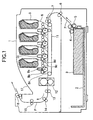
- Fig. 1 is a cross-sectional view, illustrating a general configuration of a color electrophotographic recording apparatus.
- a paper cassette 2 holds print paper 3 therein.
- a roller 4 feeds the print paper 3 into a transport path P from the paper cassette 2 on a page-by-page basis.
- Transport rollers 5, 6, and 7 transport the print paper 3 to print process cartridges 8 .
- the print paper 3 advances to a transfer section of the print process cartridge where the toner image is transferred onto the print paper 3.
- the print paper 3 advances to a fixing unit 12 and then discharging roller 13, 14, 15 and 16 drive the print paper 3 into a paper stacker 17.
- Each print process cartridge 8 includes a photoconductive drum 8a, a charging roller 8b, a developing roller 8c, a toner supplying roller 8d, a toner cartridge 9, and a cleaning unit 8e.
- the photoconductive drum 8a is a photoconductive body driven in rotation by a drum motor, not shown.
- the charging roller 8b charges the surface of the photoconductive drum 8a.
- the exposingunit 10 illuminates the charged surface of the photoconductive drum 8a to form an electrostatic latent image.
- the toner cartridge 9 supplies toner to the developing unit.
- the toner supplying roller 8d in the developing unit supplies toner to the developing roller 8c, which in turn supplies the toner to the electrostatic latent image to develop the electrostatic latent image into a toner image.
- the cleaning unit 8e scrapes the toner off the photoconductive drum 8a to clean the photoconductive drum 8a.
- the transfer unit 11 has transfer rollers that face corresponding photoconductive drums 8a to define transfer points between the photoconductive drums and the transfer rollers. When the print paper 3 passes each transfer point, a toner image of a corresponding color is transferred from the photoconductive drum onto the print paper 3.
- Fig. 2 is a perspective view of a toner cartridge according to a first embodiment.
- Fig. 3 is a cross-sectional view of the toner cartridge when it remains sealed.
- Fig. 4 is a cross-sectional view of a cartridge that has reached the end of its lifetime.
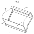
- Fig. 5 is a perspective view, illustrating a movable partitioning mechanism having a bag-shaped deformable partition.
- the toner cartridge 9 according to the embodiment will be described with reference to Figs. 2-5 .
- the toner cartridge 9 has a movable partitioning mechanism 18 that includes a swingable plate 18a, a bag-shaped deformable partition 18b, an upper partition 18d, and a lower partition 18c.
- the movable partitioning mechanism 18 divides an inner space of the toner cartridge 9 into a fresh toner chamber B and a waste toner chamber C.
- a deformable partition 18b is disposed between the lower partitioning wall 18c near a swingable plate 18a and an upper portion of the upper partitioning wall 18d.
- the deformable partition 18b is fixed at its one endportion to the upper end of the upper partitioning wall 18d and at its other end to the upper end of the lower partitioning wall 18c.
- the flexible partition 18b defines the fresh toner chamber B and the waste toner chamber C that are sealed against each other, preventing the toner in the fresh toner chamber B form being mixed with the toner in the waste toner chamber C.
- the swingable plate 18a is pivotally mounted to the upper end of the lower partitioning wall 18c. As shown in Fig. 3 , a spring, not shown, urges the swingable plate 18a in a direction shown by arrow A.
- the fresh toner in the fresh toner chamber B decreases gradually.
- the residual toner on the photoconductive drum 8a is removed from the photoconductive drum 8a and collected into the waste toner chamber C by a toner collecting mechanism provided on a die frame, not shown.
- the swingable plate 18a will be inclined gradually by the spring, not shown, in the direction shown by arrow A as shown in Fig. 3 .
- the waste toner chamber C increases in volume.
- the first embodiment has been describe with respect to a case in which the waste toner chamber C gradually increases in volume as the amount of waste toner collected in the chamber C increases.
- a modification can be made such that when the amount of waste toner exceeds a certain value, the urging force of the spring is large enough to allow the swingable plate 18a to swing.
- the modification allows the volume of the waste toner chamber C to increase when no fresh toner is present in the fresh toner chamber B, preventing toner clump in the waste toner chamber C.
- a second embodiment differs from the first embodiment in the interior structure of the toner cartridge.
- Fig. 6 is a perspective view of the toner cartridge according to the second embodiment.
- Fig. 7 is a cross-sectional view of the toner cartridge when it remains sealed.
- Fig. 8 is a cross-sectional view of the toner cartridge when it is empty of fresh toner.
- Fig. 9 is a perspective view of a movable partitioning mechanism having a bag-shaped deformable partition.
- the toner cartridge has a lower partitioningwall 19c, an upper partitioning wall 19a, and a bag-shaped deformable partition 19b that defines the toner chamber B and the waste toner chamber C.
- the bag-shaped deformable partition 19b, upper partitioning wall 19a, and lower partitioning wall 19c are integral with one another so that a small force can cause the bag-shaped deformable partition 19b to displace toward the fresh toner chamber B or toward the waste toner chamber C.
- the fresh toner in the fresh toner chamber B decreases gradually.
- the residual toner is removed from the photoconductive drum, and is collected by the toner collecting mechanism into the waste toner chamber C.
- the waste toner collected into the waste toner chamber C is moved by a later described spiral shaft from near end to the far end in the waste toner chamber C.
- the waste toner is gathered toward the middle of the waste toner chamber C and applies pressure against the deformable partition 19b, so that the bag-shaped partitioning 19b is pushed by the waste toner toward the fresh toner chamber.
- the waste toner chamber C increases in volume by an amount of the movement of the deformable partition 19b.
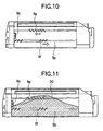
- Fig. 10 is a cross-sectional side view, illustrating the interior of a toner cartridge according to the second embodiment.
- Fig. 11 is a cross-sectional view, illustrating the waste toner held in the waste toner chamber of the toner cartridge according to the second embodiment.
- the spiral shaft 9e is rotated to move the pile of toner 20 toward the middle of the waste toner chamber C.
- a conventional spiral shaft has a vane 9f that spans across the entire length of the spiral shaft 9e so as to move the waste toner to the end of waste toner chamber C.
- the spiral shaft 9e according to the second embodiment has the vane 9f shaft so that the bag-shaped deformable partition 19b efficiently deforms into the adjacent chamber.
- the spiral shaft 9g has a vane that describes a spiral in the opposite direction to the spiral shaft 9e, the vane causing the top of the pile of the waste toner 20 to fall toward an waste toner inlet 9b.
- the toner in the fresh toner chamber B is used in developing and residual toner is removed from the photoconductive drum and collected by the toner collecting mechanism, not shown into the waste toner chamber C.
- the spiral shaft 9e causes the waste toner 20 in the waste toner chamber C to move to the end of the waste toner chamber C. Because the vane 9f extends only as far as the middle of shaft 9e, the waste toner 20 begins to pile up at a longitudinal middle of the bag and the pile will grow there. As a result, the waste toner will produce a pressure that causes the bag to extend toward the fresh toner chamber B easily and the pile of the waste toner 20 to fall toward a waste toner inlet 9b. Thus, the waste toner 20 is distributed all over the floor in the waste toner chamber C, allowing efficient use of the toner holding space.
- the deformable partition 19b that defines the boundary between the fresh toner chamber B and the waste toner chamber C deforms substantially uniformly across the length of the waste toner chamber C, ensuring that a space holding the waste toner 20 is enlarged. Because the collected waste toner 20 is distributed all over floor in the waste toner chamber C, a limited small space can be efficiently utilized.
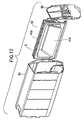
- Fig. 12 is a perspective view, illustrating the general configuration of a toner cartridge according to a third embodiment.
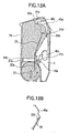
- Fig. 13A is a cross-sectional view, illustrating the toner cartridge according to the third embodiment.
- Fig. 13B is a fragmentary side view of a film and a bag-shaped deformable partition.
- the toner cartridge 9 includes an outer case 9a, a movable partitioning mechanism 40 slidably assembled into the outer case 9a, and a side wall 9b that closes the side of the outer case 9a.
- the movable partitioning mechanism 40 has a bag-shaped deformable partition 40a, which is assembled in a unitary construction.
- the fresh toner chamber B and waste toner chamber C are defined in the outer case 9a a shown in Fig. 13A .
- the movable partitioning mechanism 40 can disassembled from the outer case 9a so that the movable partitioning mechanism can be re-used by simply replacing a later described sealing member 24.
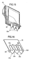
- Figs. 14 and 15 are expanded perspective views, illustrating the detail of a movable partitioning mechanism 40 in Fig. 12 .
- Fig. 16 is a perspective view of a film assembled into the movable partitioning mechanism 40.
- Fig. 17 is a perspective view, illustrating the deformable partition provided to the movable partitioning mechanism.
- the bag-shaped deformable partition 40a ( Fig. 17 ) is inserted in a recess 40e formed in the movable partitioning mechanism 40.
- the outer peripheral portion 40d of the deformable partition 40a is welded to the end portion 40c of the frame 40b.
- the deformable partition 40a defines the fresh toner chamber B and the waste toner chamber C.
- the movable partitioning mechanism 40 also has a film 22 having its tip attached to the bag-shaped deformable partition 40a by means of a tape 22f as shown in Fig. 13B and Fig. 14 .
- the film 22 is movable with the bag-shaped deformable partition 40a in the direction shown by an arrow.
- the material and thickness of the deformable partition 40a are selected such that the deformable partition 40a can easily deform into the adjacent chamber.
- the deformable partition 40a is vacuum-molded from a sheet of polyethylene or polypropylene by using a concave mold.
- the thickness t of the deformable partition 40a is in the range of 0.2 mm ⁇ t ⁇ 0.4 mm.
- the thickness t is such that t ⁇ 0.2 mm, there may be a large variation of thickness, making it difficult to properly mold the deformable partition 40a. If the thickness t is in the relation that t >0.4 mm, the bag loses flexibility significantly to such an extent that a small pressure applied by the waste toner 20 is not enough to cause the bag-shaped deformable partition 40a to deform. Therefore, a sufficient amount of waste toner cannot be collected.
- the frame 40b has an outer end on which a sealing member (sponge) 24, shown by hatching.
- the sealing member 24 seals between the outer end and the outer case 9a when the movable partitioning mechanism 40 is inserted into the toner cartridge.
- the sealing member 24 isolates the fresh toner chamber B from the waste toner chamber C completely, so that the toners in the both chambers are not mixed with each other.
- the frame 40b of the movable partitioning mechanism 40 has guides 21a-21d. As shown in Fig. 13 , there are provided guides 20a-20d on the inner wall surface of the outer case 9a.
- the aforementioned guides of the frame 40b engage the aforementioned guides of the outer case 9a, thereby allowing the outer case 9c to smoothly guide the frame 40b.
- the frame 40b Upon completion of insertion of the frame 40b, the frame 40b is accurately positioned in the outer case 9a.
- the guides 21a-21d of the frame 40b serve to add mechanical strength to the frame 40b.
- Fig. 17 illustrates the bag-shaped deformable partition 40a before it is attached to the movable partitioning mechanism 40.
- the deformable partition 40a has an outer peripheral portion bonded to the frame 40b by an adhesive.
- the film 22 has, three large holes 22f, three slits 22b, three holes 22c, and one hole 22d, which are fitted to guides 23 of the frame 40b.
- the film 22 is disposed on the inside of the fresh toner chamber B.
- the film 22 is detachably mounted at a portion near tips 22a for the reasons, which will be described later.
- the tips 22 project into a rotational path of an agitator bar 21 to agitate the toner in the fresh toner in the chamber B.
- the film 22 is configured to the deformable partition 40a, i.e. , the film 22 is bent as shown in Figs. 15 and 16 .
- the agitator bar 21 rotates to engage the tips 22a, causing the tips 22a to flex.
- the agitator bar 21 further rotates to subsequently release the tips 22a, so that the film 22 vibrates lightly in its entirety.
- the film 22 is mounted to the movable partitioning mechanism 40 in such a way that it will not come off the frame 40b when the agitator bar 21 continues to rotates, cycling to move into and out of engagement with the tips 22a.
- the agitator bar 21 rotates in a direction shown by an arrow to agitate the toner, thereby supplying the toner to the developing unit, not shown, at all times.
- the film 22 is made of, for example, polyester and has a thickness t in the range of 0.05 mm ⁇ t ⁇ 0.25 mm, and preferably t ⁇ 0.1 mm. A thickness t less than 0.05 mm cannot make the film 22 resilient enough to add vibration to the toner in the fresh toner chamber B when the tips 22a are released from the agitator bar 21.
- a thickness t greater than 0.25 mm makes the film too rigid, so that the pressure given by the waste toner is not large enough to cause the deformable partition 40a to deform toward the fresh toner chamber B. Thus, the waste toner chamber C cannot hold a large amount of waste toner.
- the film 22 is detachably mounted to the frame 40b, the film 22 can be disassembled for cleaning.
- the toner cartridge according to the third embodiment operates as follows: As printing is performed repeatedly, the fresh toner in the fresh toner chamber B is consumed gradually and the residual toner is removed from the photoconductive drum and collected into the waste toner chamber C. The waste toner 20 in the waste toner chamber C is moved further into the chamber C by the spiral shaft 9e ( Fig. 10 ). Thus, the waste toner 20 will pile up with its top located in the middle of the longitudinally extending waste toner chamber C. The pile of the waste toner 20 produces pressure to push the deformable partition 40a toward the fresh toner chamber B. As the waste toner 20 increases, the bag-shaped deformable partition 40a will extend toward the fresh toner chamber B as shown in Fig. 17 , so that a larger amount of waste toner 20 can be held in the waste toner chamber C.
- the opening, through which the waste toner is introduced into the waste toner chamber C, is located below a swelled portion of the bag-shaped deformable partition 40a.
- the deformable partition 40a is caused to extend toward the fresh toner chamber B after the waste toner piles up in the waste toner chamber C. This feature will be described in more detail with reference to Figs. 18-22 .
- Fig. 18 is a perspective view of a side wall 17 when the toner cartridge 9 is seen from outside of the toner cartridge.
- a support 34 to surround an opening 37.
- the support 34 receives a resilient foaming sponge 35 having a thickness of several millimeters.
- An outer cover 36 is attached in the outer surface of the side wall 17, thereby preventing the foaming sponge 35 from disengaging from the side wall 17.
- the foaming sponge 35 has a hole 35a formed in the middle through which a toner discharging beak 42 enters into the waste toner chamber C through the opening 37.
- the foaming sponge 35 engages the toner discharging beak 42.
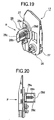
- Fig. 19 is a perspective view of the side wall 17 when the toner cartridge is seen in a direction shown by arrow Q in Fig. 18 .
- Fig. 19 illustrates the opening 37 closed by an opening/closing member 28a, i.e. , when the toner-discharging beak 42 is not pushed into the toner cartridge.
- an inner plate 27 is fixed to the inner surface of the side wall 17 by means of fitting member, not shown.
- the inner plate 27 has an opening/closingmechanism 28 mounted thereto .
- the opening/closing mechanism 28 includes an opening/closing member 28a that closes the opening 37 from the inside of the toner cartridge, a frame 28c that movably holds the opening/closing member 28a, a spring 28b that urges the opening/closing member 28a outwardly, and a movable member 28d to which one end of the spring 28b is secured.
- Fig. 20 is a side view when the side wall 17 is seen froma direction shown by arrow R in Fig. 19 .
- Fig. 21 illustrates the opening 37 when the opening/closing member 28a closes the opening 37.
- Fig. 22 illustrates the opening 37 when it is opened.
- the opening 37 remains closed until the toner cartridge has been attached to the image forming apparatus.
- the toner discharging beak 42 pushed the opening/closing member 28a in a direction shown by arrow P.
- the opening/closing member 28a moves along the slide against the urging force of the spring 28b, so that the toner transport path on the image forming apparatus communicates with the waste toner chamber C of the toner cartridge.
- the toner-discharging beak 42 enters the waste toner chamber C by a predetermined distance and is maintained where it is. This ensures that the residual toner delivered to the toner cartridge falls into the waste toner chamber C.
- the toner discharging beak 42 is withdrawn from the opening 37, so that the opening/closing member 28a is urged by the spring 28b to close the opening 37 .
- the toner in the waste toner chamber C will not leak.
- the opening 37 through which the waste toner chamber C receives the residual toner is located below the bag-shaped deformable partition 40a. Therefore, the waste toner chamber C can be disposed as close to the image forming section below the cartridge as possible. This configuration provides a shorter toner-transporting path, reducing the possibility of waste toner being clogged in the toner-transporting path.
Landscapes
- Physics & Mathematics (AREA)
- General Physics & Mathematics (AREA)
- Life Sciences & Earth Sciences (AREA)
- Engineering & Computer Science (AREA)
- Environmental & Geological Engineering (AREA)
- Sustainable Development (AREA)
- Cleaning In Electrography (AREA)
- Dry Development In Electrophotography (AREA)
Claims (24)
- Récipient de développeur ayant une première chambre (B) qui contient un développer neuf et une deuxième chambre (C) qui contient un développeur de déchets, comprenant :une séparation (19a+19b+19c, 40) fournie dans le récipient de développeur pour diviser un espace intérieur dans le récipient de développeur entre la première chambre et la deuxième chambre,caractérisé en ce queladite séparation (19a+19b+19c, 40) a une cloison inférieure (19c, 40c), une cloison supérieure (19a) et une partie mobile (19b, 40a, 22) montée sur une extrémité supérieure de la cloison inférieure et de la cloison supérieure ;dans lequel lorsqu'une quantité du développeur de déchets dans la deuxième chambre est inférieure à l'extrémité supérieure de la cloison inférieure, ladite partie mobile ne se déplace pas ;dans lequel uniquement après que la quantité du développeur de déchets dans la deuxième chambre a dépassé l'extrémité supérieure de la cloison inférieure et le développeur de déchets applique une pression contre ladite partie mobile, ladite partie mobile est configurée pour être poussée par le développeur de déchets vers la première chambre de sorte qu'un volume de la deuxième chambre augmente en fonction de la quantité du développer de déchets dans la deuxième chambre et en fonction de la réduction progressive du développeur neuf dans ladite première chambre (B).
- Récipient de développeur selon la revendication 1, dans lequel ladite séparation est telle que la première chambre (B) et la deuxième chambre (C) s'étendent sensiblement en parallèle entre elles et sont partiellement adjacentes entre elles horizontalement.
- Récipient de développeur selon la revendication 1, dans lequel ladite séparation (18, 40) fonctionne de manière à ce que le volume de la première chambre (B) diminue et le volume de la deuxième chambre (C) augmente.
- Récipient de développeur selon la revendication 1, dans lequel ladite cloison inférieure supporte la partie mobile, et dans lequel la deuxième chambre (C) a une entrée de développeur de déchets (9b), à travers laquelle la deuxième chambre (C) reçoit le développeur de déchets, l'entrée (9b) étant située sous la partie mobile.
- Récipient de développeur selon la revendication 4, dans lequel la partie mobile (19b) est un élément en forme de sachet déformable (19b).
- Récipient de développeur selon la revendication 5, dans lequel l'élément en forme de sachet a une épaisseur dans la plage de 0,2 à 0,4 mm.
- Récipient de développeur selon l'une quelconque des revendications 1 à 6, dans lequel la séparation (40) est insérée de manière détachable dans le récipient de développeur.
- Récipient de développeur selon l'une quelconque des revendications 1 à 7, dans lequel la première chambre a un clapet élastique (22) s'étendant dans la première chambre.
- Récipient de développeur selon la revendication 8, dans lequel la première chambre (B) a une barre d'agitateur (21) qui agite le développer neuf dans la première chambre (B),
dans lequel le clapet élastique (22) est un film (22), dans lequel lorsque la barre d'agitateur (21) agite le développeur neuf, le film (22) se met en prise avec la barre d'agitateur de sorte que le film (22) se plie puis se met hors prise de la barre d'agitateur (21). - Récipient de développeur selon l'une quelconque des revendications 1 à 3, dans lequel la deuxième chambre (C) s'étend dans une direction longitudinale et a un premier élément de transport (9g) à l'intérieur de celle-ci qui s'étend dans la direction longitudinale de la deuxième chambre (C) et une entrée de développeur de déchets (9b) située à une première d'extrémités opposées de la deuxième chambre (C),
dans lequel le premier élément de transport (9g) transporte le développeur de déchets d'une deuxième des extrémités opposées à la première des extrémités opposées. - Récipient de développeur selon la revendication 10, dans lequel le premier élément de transport (9g) a une ailette en spirale (9f) formée sur celui-ci, l'ailette en spirale s'étendant d'une extrémité du premier élément de transport à une partie du premier élément de transport.
- Récipient de développeur selon la revendication 11, dans lequel la deuxième chambre comprend un deuxième élément de transport (9e) à l'intérieur de celle-ci qui s'étend au-dessous du premier élément de transport (9g) dans la direction longitudinale de la deuxième chambre (C),
dans lequel le deuxième élément de transport (9e) transporte le développeur de déchets de la première des extrémités opposées à la deuxième des extrémités opposées. - Récipient de développeur selon l'une quelconque des revendications 1 à 12, dans lequel ladite séparation fonctionne pour réduire le volume de la première chambre et pour augmenter le volume de la deuxième chambre (C) lorsque la quantité de développeur de déchets dépasse la valeur prédéterminée.
- Appareil de formation d'images incorporant ledit récipient de développeur selon la revendication 1.
- Appareil de formation d'images selon la revendication 14, dans lequel ladite séparation a une partie mobile et une cloison inférieure qui supporte la partie mobile,
dans lequel la deuxième chambre (C) a une entrée de développeur de déchets à travers laquelle la deuxième chambre (C) reçoit le développeur de déchets, l'entrée de développeur de déchets (9b) étant située sous la partie mobile. - Appareil de formation d'images selon la revendication 15, dans lequel la partie mobile est un élément en forme de sachet déformable (19b).
- Appareil de formation d'images selon la revendication 16, dans lequel l'élément en forme de sachet (19b) a une épaisseur dans la plage de 0,2 à à 0,4 mm.
- Appareil de formation d'images selon l'une quelconque des revendications 14 à 17, dans lequel la séparation est insérée de manière détachable dans le récipient de développeur.
- Appareil de formation d'images selon l'une quelconque des revendications 14 à 18, dans lequel la première chambre (B) a un clapet élastique (22) s'étendant dans la première chambre (B).
- Appareil de formation d'images selon l'une quelconque des revendications 14 à 19, dans lequel la première chambre (B) a une barre d'agitateur (21) qui agite le développer neuf dans la première chambre (B),
dans lequel le clapet élastique (22) est un film (22), dans lequel lorsque la barre d'agitateur (21) agite le développeur neuf, le film se met en prise avec la barre d'agitateur (21) de sorte que le film se plie puis se met hors prise de la barre d'agitateur (21). - Appareil de formation d'images selon l'une quelconque des revendications 14 20, dans lequel la deuxième chambre (C) s'étend dans une direction longitudinale et a un premier élément de transport (9g) à l'intérieur de celle-ci qui s'étend dans la direction longitudinale de la deuxième chambre (C) et une entrée de développeur de déchets (9b) située à une première d'extrémités opposées de la deuxième chambre (C),
dans lequel le premier élément de transport (9g) transporte le développeur de déchets d'une deuxième des extrémités opposées de la deuxième chambre (C) à la première des extrémités opposées. - Appareil de formation d'images selon la revendication 21, dans lequel la deuxième chambre (C) comprend un deuxième élément de transport (9e) à l'intérieur de celle-ci qui s'étend au-dessous du premier élément de transport (9g) dans la direction longitudinale de la deuxième chambre (C),
dans lequel le deuxième élément de transport (9e) transporte le développeur de déchets de la première des extrémités opposées de la deuxième chambre à la deuxième des extrémités opposées. - Appareil de formation d'images selon la revendication 22, dans lequel le deuxième élément de transport (9e) a une ailette en spirale formée sur celui-ci, l'ailette en spirale (9f) s'étendant de la première des extrémités opposées au milieu du deuxième élément de transport (9e).
- Appareil de formation d'images selon l'une quelconque des revendications 14 à 23, dans lequel ladite séparation fonctionne de manière à ce que le volume de la première chambre (B) diminue et le volume de la deuxième chambre (C) augmente.
Applications Claiming Priority (2)
| Application Number | Priority Date | Filing Date | Title |
|---|---|---|---|
| JP2002153482 | 2002-05-28 | ||
| JP2002153482A JP4086547B2 (ja) | 2002-05-28 | 2002-05-28 | 現像剤カートリッジ及び画像形成装置 |
Publications (2)
| Publication Number | Publication Date |
|---|---|
| EP1367459A1 EP1367459A1 (fr) | 2003-12-03 |
| EP1367459B1 true EP1367459B1 (fr) | 2009-10-28 |
Family
ID=29417164
Family Applications (1)
| Application Number | Title | Priority Date | Filing Date |
|---|---|---|---|
| EP03012052A Expired - Lifetime EP1367459B1 (fr) | 2002-05-28 | 2003-05-28 | Récipient de développeur pour un appareil de formation d'images avec une chambre de toner de déchets |
Country Status (4)
| Country | Link |
|---|---|
| US (1) | US6904249B2 (fr) |
| EP (1) | EP1367459B1 (fr) |
| JP (1) | JP4086547B2 (fr) |
| DE (1) | DE60329805D1 (fr) |
Families Citing this family (32)
| Publication number | Priority date | Publication date | Assignee | Title |
|---|---|---|---|---|
| JP2006284665A (ja) * | 2005-03-31 | 2006-10-19 | Kyocera Mita Corp | トナー収納容器及びフルカラー画像形成装置 |
| JP2006301467A (ja) * | 2005-04-25 | 2006-11-02 | Kyocera Mita Corp | 画像形成装置 |
| JP4315933B2 (ja) * | 2005-07-21 | 2009-08-19 | 株式会社沖データ | 現像剤カートリッジ、現像装置、及び画像形成装置 |
| JP4610468B2 (ja) * | 2005-11-04 | 2011-01-12 | 株式会社リコー | トナー回収装置、作像ユニット及び画像形成装置 |
| JP5002183B2 (ja) * | 2006-04-18 | 2012-08-15 | キヤノン株式会社 | 現像剤搬送装置及び画像形成装置 |
| JP4953752B2 (ja) * | 2006-10-13 | 2012-06-13 | 株式会社リコー | トナー搬送装置、プロセスカートリッジ及び画像形成装置 |
| JP4990040B2 (ja) * | 2006-11-01 | 2012-08-01 | 株式会社リコー | 現像剤補給装置、画像形成装置 |
| JP4924006B2 (ja) * | 2006-12-20 | 2012-04-25 | コニカミノルタビジネステクノロジーズ株式会社 | トナー充填方法 |
| JP5103895B2 (ja) * | 2006-12-25 | 2012-12-19 | 富士ゼロックス株式会社 | 現像剤収容容器、並びに現像剤収容容器の組立て方法及び再生方法 |
| JP5039390B2 (ja) * | 2007-02-02 | 2012-10-03 | 株式会社リコー | プロセスカートリッジ及び画像形成装置 |
| US20080184606A1 (en) * | 2007-02-06 | 2008-08-07 | Xerox Corporation | Alternate appearance cover for electrophotographic machines |
| JP5115015B2 (ja) * | 2007-04-20 | 2013-01-09 | 富士ゼロックス株式会社 | トナーカートリッジ |
| JP4608535B2 (ja) | 2007-11-27 | 2011-01-12 | 株式会社沖データ | 現像剤回収容器、現像剤カートリッジ、現像ユニット、及び画像形成装置 |
| JP5188186B2 (ja) * | 2008-01-10 | 2013-04-24 | キヤノン株式会社 | カートリッジ及びプリンタ装置 |
| JP5413729B2 (ja) * | 2009-01-30 | 2014-02-12 | 株式会社リコー | 粉体収容装置及び画像形成装置 |
| JP4831204B2 (ja) * | 2009-04-28 | 2011-12-07 | ブラザー工業株式会社 | 画像形成装置および像担持体ユニット |
| JP5033170B2 (ja) * | 2009-12-02 | 2012-09-26 | 株式会社沖データ | 現像剤収容器、画像形成ユニット、及び画像形成装置 |
| JP5748093B2 (ja) | 2011-01-11 | 2015-07-15 | 株式会社リコー | トナー容器、及び、画像形成装置 |
| JP5771797B2 (ja) * | 2011-11-29 | 2015-09-02 | キヤノン株式会社 | 現像装置、カートリッジ、及び電子写真画像形成装置 |
| JP2013126361A (ja) * | 2011-12-16 | 2013-06-24 | Hitachi Automotive Systems Ltd | 車載用電子制御装置 |
| US9042778B2 (en) * | 2012-07-30 | 2015-05-26 | Ricoh Company, Ltd. | Powder refilling device, process cartridge and image including same, and powder refilling method |
| JP6120694B2 (ja) * | 2013-06-24 | 2017-04-26 | キヤノン株式会社 | カートリッジ、プロセスカートリッジ、現像カートリッジ、及び画像形成装置 |
| JP2016133753A (ja) | 2015-01-22 | 2016-07-25 | 株式会社沖データ | 現像剤収容器及び画像形成装置 |
| JP6533679B2 (ja) * | 2015-03-20 | 2019-06-19 | 株式会社沖データ | 現像剤収容部材、画像形成ユニットおよび画像形成装置 |
| JP6308173B2 (ja) * | 2015-06-11 | 2018-04-11 | 京セラドキュメントソリューションズ株式会社 | トナー容器及び画像形成装置 |
| JP6516330B2 (ja) * | 2015-10-27 | 2019-05-22 | 株式会社沖データ | 画像形成装置 |
| JP6753112B2 (ja) * | 2016-03-31 | 2020-09-09 | ブラザー工業株式会社 | 現像剤カートリッジおよび現像剤収容ユニット |
| KR20180054025A (ko) * | 2016-11-14 | 2018-05-24 | 에이치피프린팅코리아 주식회사 | 현상제 카트리지 및 이를 채용한 전자사진방식 화상형성장치 |
| JP2018124362A (ja) | 2017-01-31 | 2018-08-09 | 株式会社沖データ | 画像形成装置 |
| US11402765B2 (en) | 2019-07-15 | 2022-08-02 | Hewlett-Packard Development Company, L.P. | Print material container |
| CN113534641A (zh) * | 2021-07-09 | 2021-10-22 | 珠海天威飞马打印耗材有限公司 | 一种大容量碳粉盒 |
| JP2024073672A (ja) * | 2022-09-30 | 2024-05-30 | ヒューレット-パッカード デベロップメント カンパニー エル.ピー. | 排出された現像剤用のチャンバを備えた現像装置 |
Citations (1)
| Publication number | Priority date | Publication date | Assignee | Title |
|---|---|---|---|---|
| US6339689B1 (en) * | 1999-02-09 | 2002-01-15 | Fujitsu Peripherals Limited | Toner collection device with displaceable partition |
Family Cites Families (10)
| Publication number | Priority date | Publication date | Assignee | Title |
|---|---|---|---|---|
| JPS59184373A (ja) | 1983-04-05 | 1984-10-19 | Fuji Xerox Co Ltd | 供給・回収トナ−ボトル |
| JPS617865A (ja) * | 1984-06-22 | 1986-01-14 | Sharp Corp | 画像形成装置 |
| JPS63298370A (ja) | 1987-05-29 | 1988-12-06 | Ricoh Co Ltd | トナ−カ−トリツジ |
| JPH03273272A (ja) * | 1990-03-22 | 1991-12-04 | Konica Corp | 画像記録装置の現像剤収納容器 |
| JPH05249766A (ja) | 1992-03-06 | 1993-09-28 | Ricoh Co Ltd | クリーナ・トナー・マガジン |
| JP3301306B2 (ja) * | 1996-04-15 | 2002-07-15 | カシオ電子工業株式会社 | トナー回収装置及びこれを備えたプロセスユニット |
| JPH11212344A (ja) | 1998-01-21 | 1999-08-06 | Oki Data Corp | トナー補給用容器 |
| JP4105275B2 (ja) | 1998-03-13 | 2008-06-25 | 株式会社沖データ | トナーカートリッジ、印刷プロセスカートリッジ及び電子写真記録装置 |
| US6363233B1 (en) | 2000-06-13 | 2002-03-26 | Oki Data Corporation | Compact toner cartridge with fresh and waste toner chambers |
| GB2352055B (en) * | 1999-07-12 | 2003-05-21 | Gcc Man Ltd | A service unit for an electrographic apparatus |
-
2002
- 2002-05-28 JP JP2002153482A patent/JP4086547B2/ja not_active Expired - Lifetime
-
2003
- 2003-05-27 US US10/446,231 patent/US6904249B2/en not_active Expired - Lifetime
- 2003-05-28 DE DE60329805T patent/DE60329805D1/de not_active Expired - Lifetime
- 2003-05-28 EP EP03012052A patent/EP1367459B1/fr not_active Expired - Lifetime
Patent Citations (1)
| Publication number | Priority date | Publication date | Assignee | Title |
|---|---|---|---|---|
| US6339689B1 (en) * | 1999-02-09 | 2002-01-15 | Fujitsu Peripherals Limited | Toner collection device with displaceable partition |
Also Published As
| Publication number | Publication date |
|---|---|
| US6904249B2 (en) | 2005-06-07 |
| EP1367459A1 (fr) | 2003-12-03 |
| JP4086547B2 (ja) | 2008-05-14 |
| US20030223776A1 (en) | 2003-12-04 |
| JP2003345116A (ja) | 2003-12-03 |
| DE60329805D1 (de) | 2009-12-10 |
Similar Documents
| Publication | Publication Date | Title |
|---|---|---|
| EP1367459B1 (fr) | Récipient de développeur pour un appareil de formation d'images avec une chambre de toner de déchets | |
| US5508794A (en) | Developer recycling system and developer cartridge therefor | |
| JP3364632B2 (ja) | トナー補給装置 | |
| KR102417544B1 (ko) | 현상제 보급 용기 및 현상제 보급 시스템 | |
| EP1460487A2 (fr) | Réservoir d'alimentation en développeur et son raccord d'entraînement | |
| EP2237112B1 (fr) | Corps de stockage de révélateur, unité de formation d'images et appareil de formation d'images | |
| US6334037B1 (en) | Image forming apparatus | |
| EP3686682B1 (fr) | Système de remplissage de révélateur, procédé de fixation d'un récipient de remplissage de révélateur et unité de remplissage de révélateur | |
| US5659837A (en) | Developing device for use in image forming apparatus | |
| JP2002091149A (ja) | トナー補給容器及びトナー補給容器の再生方法 | |
| JP2011118040A (ja) | 画像形成ユニット及び画像形成装置 | |
| CN111694247B (zh) | 调色剂容器、调色剂补给装置及图像形成装置 | |
| JP2003295592A (ja) | 一体型トナー容器 | |
| JP2000181224A (ja) | トナーカートリッジ | |
| JP4467152B2 (ja) | 画像形成用現像装置 | |
| US12416880B2 (en) | Toner container | |
| JPH03221981A (ja) | 現像装置 | |
| JPH0815971A (ja) | 画像形成装置 | |
| JP6682284B2 (ja) | トナーカートリッジおよびトナー供給機構 | |
| JPH0418578A (ja) | トナーカートリッジ | |
| JPS63298370A (ja) | トナ−カ−トリツジ | |
| JP2634082B2 (ja) | ホッパー | |
| JPH0419680A (ja) | プロセスユニット | |
| US20050036802A1 (en) | Image forming apparatus and process cartridge uses in the same | |
| JP2024166543A (ja) | 現像剤収容装置、プロセスカートリッジ、及び、画像形成装置 |
Legal Events
| Date | Code | Title | Description |
|---|---|---|---|
| PUAI | Public reference made under article 153(3) epc to a published international application that has entered the european phase |
Free format text: ORIGINAL CODE: 0009012 |
|
| AK | Designated contracting states |
Kind code of ref document: A1 Designated state(s): AT BE BG CH CY CZ DE DK EE ES FI FR GB GR HU IE IT LI LU MC NL PT RO SE SI SK TR |
|
| AX | Request for extension of the european patent |
Extension state: AL LT LV MK |
|
| 17P | Request for examination filed |
Effective date: 20040512 |
|
| AKX | Designation fees paid |
Designated state(s): DE FR GB NL |
|
| 17Q | First examination report despatched |
Effective date: 20060908 |
|
| 17Q | First examination report despatched |
Effective date: 20060908 |
|
| GRAP | Despatch of communication of intention to grant a patent |
Free format text: ORIGINAL CODE: EPIDOSNIGR1 |
|
| GRAS | Grant fee paid |
Free format text: ORIGINAL CODE: EPIDOSNIGR3 |
|
| GRAA | (expected) grant |
Free format text: ORIGINAL CODE: 0009210 |
|
| AK | Designated contracting states |
Kind code of ref document: B1 Designated state(s): DE FR GB NL |
|
| REG | Reference to a national code |
Ref country code: GB Ref legal event code: FG4D |
|
| REF | Corresponds to: |
Ref document number: 60329805 Country of ref document: DE Date of ref document: 20091210 Kind code of ref document: P |
|
| PLBE | No opposition filed within time limit |
Free format text: ORIGINAL CODE: 0009261 |
|
| STAA | Information on the status of an ep patent application or granted ep patent |
Free format text: STATUS: NO OPPOSITION FILED WITHIN TIME LIMIT |
|
| 26N | No opposition filed |
Effective date: 20100729 |
|
| REG | Reference to a national code |
Ref country code: FR Ref legal event code: PLFP Year of fee payment: 14 |
|
| REG | Reference to a national code |
Ref country code: FR Ref legal event code: PLFP Year of fee payment: 15 |
|
| REG | Reference to a national code |
Ref country code: FR Ref legal event code: PLFP Year of fee payment: 16 |
|
| REG | Reference to a national code |
Ref country code: DE Ref legal event code: R081 Ref document number: 60329805 Country of ref document: DE Owner name: OKI ELECTRIC INDUSTRY CO., LTD., JP Free format text: FORMER OWNER: OKI DATA CORP., TOKIO/TOKYO, JP |
|
| REG | Reference to a national code |
Ref country code: GB Ref legal event code: 732E Free format text: REGISTERED BETWEEN 20220317 AND 20220323 |
|
| REG | Reference to a national code |
Ref country code: NL Ref legal event code: PD Owner name: OKI ELECTRIC INDUSTRY CO., LTD.; JP Free format text: DETAILS ASSIGNMENT: CHANGE OF OWNER(S), MERGE; FORMER OWNER NAME: OKI DATA CORPORATION Effective date: 20220308 |
|
| PGFP | Annual fee paid to national office [announced via postgrant information from national office to epo] |
Ref country code: NL Payment date: 20220420 Year of fee payment: 20 |
|
| PGFP | Annual fee paid to national office [announced via postgrant information from national office to epo] |
Ref country code: GB Payment date: 20220407 Year of fee payment: 20 Ref country code: FR Payment date: 20220408 Year of fee payment: 20 Ref country code: DE Payment date: 20220406 Year of fee payment: 20 |
|
| REG | Reference to a national code |
Ref country code: DE Ref legal event code: R071 Ref document number: 60329805 Country of ref document: DE |
|
| REG | Reference to a national code |
Ref country code: NL Ref legal event code: MK Effective date: 20230527 |
|
| REG | Reference to a national code |
Ref country code: GB Ref legal event code: PE20 Expiry date: 20230527 |
|
| PG25 | Lapsed in a contracting state [announced via postgrant information from national office to epo] |
Ref country code: GB Free format text: LAPSE BECAUSE OF EXPIRATION OF PROTECTION Effective date: 20230527 |