EP1367861A2 - Mikrowellenofen - Google Patents
Mikrowellenofen Download PDFInfo
- Publication number
- EP1367861A2 EP1367861A2 EP02255989A EP02255989A EP1367861A2 EP 1367861 A2 EP1367861 A2 EP 1367861A2 EP 02255989 A EP02255989 A EP 02255989A EP 02255989 A EP02255989 A EP 02255989A EP 1367861 A2 EP1367861 A2 EP 1367861A2
- Authority
- EP
- European Patent Office
- Prior art keywords
- heater
- cooking
- cooking cavity
- food
- support
- Prior art date
- Legal status (The legal status is an assumption and is not a legal conclusion. Google has not performed a legal analysis and makes no representation as to the accuracy of the status listed.)
- Withdrawn
Links
Images


Classifications
-
- F—MECHANICAL ENGINEERING; LIGHTING; HEATING; WEAPONS; BLASTING
- F24—HEATING; RANGES; VENTILATING
- F24C—DOMESTIC STOVES OR RANGES ; DETAILS OF DOMESTIC STOVES OR RANGES, OF GENERAL APPLICATION
- F24C7/00—Stoves or ranges heated by electric energy
- F24C7/04—Stoves or ranges heated by electric energy with heat radiated directly from the heating element
-
- H—ELECTRICITY
- H05—ELECTRIC TECHNIQUES NOT OTHERWISE PROVIDED FOR
- H05B—ELECTRIC HEATING; ELECTRIC LIGHT SOURCES NOT OTHERWISE PROVIDED FOR; CIRCUIT ARRANGEMENTS FOR ELECTRIC LIGHT SOURCES, IN GENERAL
- H05B6/00—Heating by electric, magnetic or electromagnetic fields
- H05B6/64—Heating using microwaves
- H05B6/647—Aspects related to microwave heating combined with other heating techniques
- H05B6/6482—Aspects related to microwave heating combined with other heating techniques combined with radiant heating, e.g. infrared heating
Definitions
- the present invention relates, in general, to microwave ovens.
- a microwave oven is an electrically operated oven, which heats and/or cooks food laid in its cooking cavity using high-frequency electromagnetic waves generated by the oscillation of a magnetron installed in a housing. That is, during an operation of the microwave oven, the magnetron inside the housing irradiates high-frequency electromagnetic waves, so-called "microwaves", through the cooking cavity.
- the microwaves thus penetrate food so as to repeatedly change the molecular arrangement of moisture in the food, thus causing the molecules of moisture to vibrate and generating frictional heat within the food to cook it.
- a microwave oven with a heater installed at the upper portion inside the cooking cavity has been proposed and used.
- the microwave oven with such a heater cooks food using microwaves irradiated from a magnetron through the cooking cavity, and, at the same time, heats the food by the heater, thus uniformly cooking the food, as well as browning the upper surface of the food to make the cooked food more palatable.
- a microwave oven with two heaters respectively installed at the upper and lower portions inside the cooking cavity and allowing a user to be free from turning food during a cooking process, has been proposed and used.
- FIG. 1 is a view, showing the construction of the cooking cavity of a conventional microwave oven with two heaters respectively installed at the upper and lower portions inside the cooking cavity.
- the microwave oven has upper and lower heaters 2 and 3 respectively installed at the upper and lower portions inside the cooking cavity 1.
- the upper heater 2 heats the upper surface of food set in the cooking cavity 1, while the lower heater 3 heats the lower surface of the food.
- the microwave oven also has a cooking tray 4, which is set on the bottom wall of the cooking cavity 1 and seats food thereon.
- a tray motor 5 is installed under the bottom wall of the cooking cavity 1, and rotates the cooking tray 4.
- a tray guide 6, with a plurality of rollers 7, is set between the tray 4 and the bottom wall of the cavity 1 to rotatably support the cooking tray 4 on the bottom wall of the cavity 1.
- the lower heater 3 is installed at a position under the tray 4, and heats the lower surface of food seated on the tray 4.
- the conventional microwave oven with the two heaters of Figure 1 has problems caused by the lower heater being installed at a position under the cooking tray. That is, the lower heater heats the elements installed around it, for example, the cooking tray, tray motor, rollers and tray guide, so it is necessary to produce the elements using heat-resistant materials capable of resisting heat radiated from the heater.
- the cooking tray, rollers and tray guide must be produced using heat-resistant materials, such as metals, and the tray motor must be produced using a material having a high thermal insulation, and the output shaft of the motor must be made of aluminium. Therefore, due to such expensive materials of the above-mentioned elements, the conventional microwave oven having the lower heater at a position under the cooking tray is increased in its production cost, and this undesirably increases the price of the microwave oven.
- the upper and lower heaters of the conventional microwave oven are spaced apart from each other by a large gap, so heat from the upper heater is not effectively transmitted to the upper surface of food laid on the cooking tray. Therefore, the upper heater is reduced in its effect of browning the upper surface of food, in comparison with the lower heater.
- the present invention has been made keeping in mind the above problems occurring in the prior art and with a view to solving or reducing at least one of these problems.
- a microwave oven comprising a cooking cavity having a top wall and a bottom wall, and a cooking tray provided on the bottom wall of the cooking cavity, further comprising: an upper heater installed inside the cooking cavity at a position adjacent to the top wall of said cooking cavity; a middle heater installed at a position between the upper heater and the cooking tray; and a food support having a predetermined height and removably set in said cooking cavity to support food thereon, said food support being positioned, in use, on the cooking tray such that the food support is arranged to rotate as the cooking tray rotates and an upper part of the food support is positioned between said upper and middle heaters, wherein, in use, the upper and middle heaters heat upper and lower surfaces of food laid on the upper part of the food support (52), at the same time.
- a second aspect provides a microwave oven comprising a cooking cavity having a top wall and a bottom wall, and a cooking tray provided on the bottom wall of the cooking cavity, further comprising: an upper heater installed inside the cooking cavity at a position adjacent to the top wall of said cooking cavity; and a middle heater installed at a position between the upper heater and the cooking tray.
- the first and/or second aspects may further comprise any of the following features in any logical combinations.
- Each of said upper and middle heaters may be pivotally attached at a first end thereof to a first sidewall of said cooking cavity by a hinge, and extends from said first end toward a second sidewall of the cooking cavity to form a second end, said second end of each of the upper and middle heaters being rotatably supported by a heater support.
- the heater support may be provided with both a heater seating groove at a front end thereof for rotatably seating the second end of an associated heater therein, and a locking lug at a rear part thereof for passing through a rear wall of the cooking cavity, said heater support being arranged to rotatably support the second end of the heater at the heater seating groove and being locked to the rear wall of the cooking cavity by a locking piece engaging with the locking lug at the outside of said rear wall.
- the locking piece may be a flat panel provided with a fitting hole consisting of a wide part and a narrow part communicating with each other, said wide part having a size larger than that of said locking lug of the heater support so as to allow the locking lug to pass through the wide part, and said narrow part having a width equal to or slightly smaller than that of said locking lug so as to forcibly stop the locking lug.
- Figure 2 is a sectional view, schematically showing the construction of the cooking cavity of a microwave oven, with upper and middle heaters specifically bent to form desired profiles and respectively installed at the upper and middle portions inside the cooking cavity in accordance with the preferred embodiment of this invention.
- the body of the microwave oven of this invention has a housing 10 seating a plurality of elements, such as a magnetron upper irradiating microwaves, therein, and a cooking cavity 20 partitioned from the housing 10 and defining a cooking chamber of the oven.
- the microwaves generated from the magnetron 11 inside the housing 10 are irradiated through the cooking cavity 20 to cook food laid in the cooking cavity 20.
- the microwave oven also has a cooking tray 21, which is set on the bottom wall 20a of the cooking cavity 20 and seats food thereon.
- a tray motor 22 is installed under the bottom wall 20a of the cooking cavity 20, and rotates the cooking tray 21 at a low speed.
- a tray guide 23, with a plurality of rollers 24, is provided under the tray 21 to rotatably support the cooking tray 21.
- An upper heater 31 is installed in the cooking cavity 20 at a position adjacent to the top wall 20b of the cooking cavity 20, and heats and cooks the upper surface of food.
- a middle heater 32 is installed at a middle position between the upper heater 31 and the cooking tray 21, and heats and cooks the lower surface of food. That is, the upper heater 31 is installed at the upper portion inside the cooking cavity 20, and the middle heater 32 is installed at the middle portion between the upper heater 31 and the cooking tray 21, so the two heaters 31 and 32 respectively heat the upper and lower surfaces of food laid at a position between them.
- Each of the two heaters 31 and 32 is rotatably held at a first end thereof on a first sidewall 20c of the cooking cavity 20 by a hinge 33 such that the two heaters 31 and 32 are rotated along with their hinges 33 around the axes of said hinges 33.
- the two heaters 31 and 32 extend from their first ends towards a second sidewall 20d of the cooking cavity 20, and are bent to be returned to the first ends, thus forming second ends.
- the second end of each heater 31 or 32 is rotatably supported by a heater support 40 installed at the rear wall 20e of the cooking cavity 20.
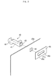
- FIG 3 is an exploded perspective view of one of the heater supports 40 rotatably supporting the second ends of the two heaters 31 and 32 in the cooking cavity 20.
- each heater support 40 comprises a hook-shaped body 41 consisting of both a heater seating groove 42 and a locking lug 43.
- the seating groove 42 is formed at the front part of the body 41, and rotatably seats the second end of a heater 31 or 32 therein.
- the locking lug 43 with a neck is formed at the rear part of the body 41, and mounts the heater support 40 to the rear wall 20e of the cooking cavity 20.
- the rear wall 20e of the cooking cavity 20 has two locking openings 44 each having a rectangular profile.
- each of the two heater supports 40 is primarily set on the rear wall 20e of the cavity 20 such that the body 41 is positioned inside the cavity 20 and the locking lug 43 passes through the opening 44 to be projected to the outside of the rear wall 20e.
- a locking piece 45 is fitted over the neck of the locking lug 43 at the outside of the rear wall 20e, thus completely mounting the heater support 40 on the rear wall 20e.
- the locking piece 45 is made of a flat panel 45, and has a keyhole-shaped fitting hole. This fitting hole consists of a wide part 45a and a narrow part 45b communicating with each other.
- the locking piece 45 is primarily fitted over the locking lug 43 at the wide part 45a, and is thereafter moved such that the neck of the locking lug 43 is stopped in the narrow part 45b.
- the size of the wide part 45a is larger than that of the locking lug 43 so as to allow the lug 43 to pass through it.
- the width of the narrow part 45b extending from the wide part 45a is equal to or slightly smaller than that of the lug 43 so as to forcibly stop the lug 43.
- the two heater supports 40 are fitted over the second ends of the heaters 31 and 32 at their seating grooves 42, and primarily set on the rear wall 20e by inserting the locking lugs 43 into the locking openings 44 of the rear wall 20e. Thereafter, a locking piece 45 is fitted over the locking lug 43 of each heater support 40 at the wide part 45a of its fitting hole, and thereafter moved in a direction as shown by the arrow "A" of Figure 3, thus stopping the locking lug 43 at the narrow part 45b of the fitting hole. The two heater supports 45 are thus completely locked to the rear wall 20e of the cooking cavity 20.
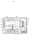
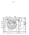
- Figures 4 and 5 show the microwave oven of this invention during a process of cooking food laid at a position between the upper and middle heaters.
- Figure 4 shows a grilling food support removably laid on the cooking tray such that its top grill is positioned between the upper and middle heaters
- Figure 5 shows an operational effect of the middle heater evenly heating the lower surface of food laid on the top grill of the grilling food support.
- the upper and middle heaters 31 and 32 are primarily rotated upward around the axes of the hinges 33 to be horizontally positioned inside the cooking cavity 20.
- the grilling food support 50 is seated on the cooking tray 21 in the cooking cavity 20.
- the grilling food support 50 is used for placing food "F" at a position between the upper and middle heaters 31 and 32 such that the upper and lower surfaces of the food are respectively browned by heat radiated from the two heaters 31 and 32.
- This food support 50 consists of a top grill 51 provided at the upper part, a lower base 52 provided at the lower part, and a column 53 connecting the top grill 51 to the lower base 52.
- the food support 50 When the grilling food support 50 is seated on the cooking tray 21 at the lower base 52, the food support 50 is rotated along with the tray 21. In such a case, the top grill 51 is positioned between the upper and middle heaters 31 and 32. When the oven is turned on after food "F" to be grilled is laid on the top grill 51, the tray 21 is rotated at a low speed. During such a rotation of the tray 21, heat from the upper and middle heaters 31 and 32 is directly transmitted to the food "F", thus browning the upper and lower surfaces of the food "F". In such a case, microwaves generated from the magnetron 11 are irradiated through the cooking cavity 20, thus cooking the food "F” by frictional heat induced by the microwaves.
- the middle heater 32 when the middle heater 32 is rotated upward and forward, it is horizontally positioned under the rear portion of the top grill of the grilling food support 50. Therefore, heat from the middle heater 32 in such a case may be not effectively transmitted to a part of the food "F" laid on the front portion of the top grill.
- the grilling food support 50 is rotated along with the cooking tray 21 at a low speed, so the parts of the food "F” laid on the front and rear portions of the top grill can be alternately positioned above the middle heater 32. Therefore, the lower surface of the food "F” can be evenly heated by the middle heater 32 regardless of the positions of parts of food on the top tray.
- the above-mentioned mechanism capable of evenly heating the lower surface of food by the middle heater 32 is also applied to the upper heater 31.
- the present invention provides a microwave oven, in which an upper heater is installed in the cooking cavity at a position adjacent to the top wall of the cooking cavity, and a middle heater is installed at a middle position between the upper heater and the cooking tray. Due to such an arrangement of the two heaters in the cooking cavity, it is possible to produce the cooking tray, tray guide, rollers and tray motor using inexpensive conventional materials which do not need to be heat-resistant.
- the cooking tray may be made of glass
- the tray guide and rollers may be produced using plastic materials
- the tray motor may be manufactured using a metal. Therefore, the cooking tray, tray guide, rollers and tray motor, made of such inexpensive materials different from conventional microwave ovens having upper and lower heaters, do not increase the production cost of the microwave ovens.
Landscapes
- Physics & Mathematics (AREA)
- Electromagnetism (AREA)
- Engineering & Computer Science (AREA)
- Chemical & Material Sciences (AREA)
- Combustion & Propulsion (AREA)
- Mechanical Engineering (AREA)
- General Engineering & Computer Science (AREA)
- Electric Ovens (AREA)
Applications Claiming Priority (2)
| Application Number | Priority Date | Filing Date | Title |
|---|---|---|---|
| KR2002030763 | 2002-05-31 | ||
| KR1020020030763A KR20030092916A (ko) | 2002-05-31 | 2002-05-31 | 전자렌지 |
Publications (1)
| Publication Number | Publication Date |
|---|---|
| EP1367861A2 true EP1367861A2 (de) | 2003-12-03 |
Family
ID=29417463
Family Applications (1)
| Application Number | Title | Priority Date | Filing Date |
|---|---|---|---|
| EP02255989A Withdrawn EP1367861A2 (de) | 2002-05-31 | 2002-08-29 | Mikrowellenofen |
Country Status (4)
| Country | Link |
|---|---|
| EP (1) | EP1367861A2 (de) |
| KR (1) | KR20030092916A (de) |
| CN (1) | CN1461913A (de) |
| RU (1) | RU2002123290A (de) |
Cited By (5)
| Publication number | Priority date | Publication date | Assignee | Title |
|---|---|---|---|---|
| EP1635616A1 (de) * | 2004-09-13 | 2006-03-15 | LG Electronics Inc. | Mikrowellenofen versehen mit einem schwenkbarem Heizstrahler |
| US20210307127A1 (en) * | 2020-03-31 | 2021-09-30 | Haier Us Appliance Solutions, Inc. | Stackable pans for cooking appliance |
| WO2021197129A1 (en) * | 2020-03-31 | 2021-10-07 | Qingdao Haier Intelligent Cooking Appliances Co., Ltd. | Cooking appliance meal cook cycle |
| WO2021197021A1 (en) * | 2020-03-31 | 2021-10-07 | Qingdao Haier Intelligent Cooking Appliances Co., Ltd. | Lamp synchronization for cooking appliance meal cook cycle |
| JP2022183270A (ja) * | 2018-12-10 | 2022-12-08 | 美的集団股▲フン▼有限公司 | オーブンを有する電子レンジ |
Families Citing this family (1)
| Publication number | Priority date | Publication date | Assignee | Title |
|---|---|---|---|---|
| JP4649501B2 (ja) * | 2008-08-08 | 2011-03-09 | シャープ株式会社 | 加熱調理器 |
Family Cites Families (6)
| Publication number | Priority date | Publication date | Assignee | Title |
|---|---|---|---|---|
| JPS6016241A (ja) * | 1984-06-07 | 1985-01-28 | Matsushita Electric Ind Co Ltd | 加熱調理器 |
| JP2607194Y2 (ja) * | 1992-01-29 | 2001-04-16 | 株式会社東芝 | 加熱調理器 |
| KR950006884U (ko) * | 1993-08-28 | 1995-03-21 | 전자레인지의 양면구이 장치 | |
| JP3023264B2 (ja) * | 1993-09-22 | 2000-03-21 | 株式会社東芝 | 加熱調理器 |
| KR950014897U (ko) * | 1993-11-15 | 1995-06-17 | 전자렌지용 히터 브라켓 고정구조 | |
| KR960035115U (ko) * | 1995-04-11 | 1996-11-21 | 전자렌지 |
-
2002
- 2002-05-31 KR KR1020020030763A patent/KR20030092916A/ko not_active Ceased
- 2002-08-13 CN CN02129767A patent/CN1461913A/zh active Pending
- 2002-08-29 RU RU2002123290/09A patent/RU2002123290A/ru not_active Application Discontinuation
- 2002-08-29 EP EP02255989A patent/EP1367861A2/de not_active Withdrawn
Cited By (6)
| Publication number | Priority date | Publication date | Assignee | Title |
|---|---|---|---|---|
| EP1635616A1 (de) * | 2004-09-13 | 2006-03-15 | LG Electronics Inc. | Mikrowellenofen versehen mit einem schwenkbarem Heizstrahler |
| JP2022183270A (ja) * | 2018-12-10 | 2022-12-08 | 美的集団股▲フン▼有限公司 | オーブンを有する電子レンジ |
| US20210307127A1 (en) * | 2020-03-31 | 2021-09-30 | Haier Us Appliance Solutions, Inc. | Stackable pans for cooking appliance |
| WO2021197129A1 (en) * | 2020-03-31 | 2021-10-07 | Qingdao Haier Intelligent Cooking Appliances Co., Ltd. | Cooking appliance meal cook cycle |
| WO2021197021A1 (en) * | 2020-03-31 | 2021-10-07 | Qingdao Haier Intelligent Cooking Appliances Co., Ltd. | Lamp synchronization for cooking appliance meal cook cycle |
| US11596032B2 (en) * | 2020-03-31 | 2023-02-28 | Haier Us Appliance Solutions, Inc. | Stackable pans for cooking appliance |
Also Published As
| Publication number | Publication date |
|---|---|
| RU2002123290A (ru) | 2004-06-20 |
| CN1461913A (zh) | 2003-12-17 |
| KR20030092916A (ko) | 2003-12-06 |
Similar Documents
| Publication | Publication Date | Title |
|---|---|---|
| JP3838666B2 (ja) | ヒータ装置を有する電子レンジ | |
| KR100677739B1 (ko) | 주사형 광파 오븐 및 이를 동작시키는 방법 | |
| US20080029503A1 (en) | Method for cooking a food with infrared radiant heat | |
| CN101910731A (zh) | 炊具 | |
| EP1399000A2 (de) | Mikrowellenofen versehen mit einem Brotroster | |
| EP1753266A2 (de) | Mikrowellenkochvorrichtung | |
| EP1392082B1 (de) | Heizelemente bei einem Mikrowellenofen | |
| US20210392724A1 (en) | Microwave oven with integrated lower surface heating plate | |
| EP1377130A2 (de) | Mikrowellenofen, und Führungsrolle, Kochplatte, Geschirr die in Mikrowellenofen benützen sind | |
| JP5492646B2 (ja) | 高周波加熱調理器 | |
| CN1461913A (zh) | 微波炉 | |
| KR100727161B1 (ko) | 가열 조리기기 | |
| JP2004012095A (ja) | 高周波加熱調理器 | |
| JP6574983B2 (ja) | 加熱調理器 | |
| KR100685987B1 (ko) | 전자 레인지 | |
| KR200157109Y1 (ko) | 전자 렌지용 그릴 석쇠 | |
| JPH04263704A (ja) | 加熱調理機 | |
| CN102379634A (zh) | 烤箱 | |
| US20080128404A1 (en) | Cooking subassembly for oven and method | |
| JP2004069088A (ja) | 高周波加熱装置 | |
| KR20040087219A (ko) | 전자레인지 | |
| JPH0714725Y2 (ja) | ヒータ付高周波加熱調理装置 | |
| KR200154589Y1 (ko) | 구이 겸용 전자렌지 | |
| KR200157113Y1 (ko) | 전자렌지용 그릴 석쇠 | |
| KR200157108Y1 (ko) | 전자 렌지용 그릴 석쇠 |
Legal Events
| Date | Code | Title | Description |
|---|---|---|---|
| PUAI | Public reference made under article 153(3) epc to a published international application that has entered the european phase |
Free format text: ORIGINAL CODE: 0009012 |
|
| 17P | Request for examination filed |
Effective date: 20020910 |
|
| AK | Designated contracting states |
Kind code of ref document: A2 Designated state(s): AT BE BG CH CY CZ DE DK EE ES FI FR GB GR IE IT LI LU MC NL PT SE SK TR |
|
| AX | Request for extension of the european patent |
Extension state: AL LT LV MK RO SI |
|
| STAA | Information on the status of an ep patent application or granted ep patent |
Free format text: STATUS: THE APPLICATION HAS BEEN WITHDRAWN |
|
| 18W | Application withdrawn |
Effective date: 20040323 |