EP1368149B1 - Outil de coupe - Google Patents
Outil de coupe Download PDFInfo
- Publication number
- EP1368149B1 EP1368149B1 EP02711742A EP02711742A EP1368149B1 EP 1368149 B1 EP1368149 B1 EP 1368149B1 EP 02711742 A EP02711742 A EP 02711742A EP 02711742 A EP02711742 A EP 02711742A EP 1368149 B1 EP1368149 B1 EP 1368149B1
- Authority
- EP
- European Patent Office
- Prior art keywords
- insert
- base
- tool
- tool holder
- grooves
- Prior art date
- Legal status (The legal status is an assumption and is not a legal conclusion. Google has not performed a legal analysis and makes no representation as to the accuracy of the status listed.)
- Expired - Lifetime
Links
Images


Classifications
-
- B—PERFORMING OPERATIONS; TRANSPORTING
- B23—MACHINE TOOLS; METAL-WORKING NOT OTHERWISE PROVIDED FOR
- B23B—TURNING; BORING
- B23B27/00—Tools for turning or boring machines; Tools of a similar kind in general; Accessories therefor
- B23B27/08—Cutting tools with blade- or disc-like main parts
-
- B—PERFORMING OPERATIONS; TRANSPORTING
- B23—MACHINE TOOLS; METAL-WORKING NOT OTHERWISE PROVIDED FOR
- B23B—TURNING; BORING
- B23B2205/00—Fixation of cutting inserts in holders
- B23B2205/10—Fixation of cutting inserts in holders using two or more fixation screws
-
- B—PERFORMING OPERATIONS; TRANSPORTING
- B23—MACHINE TOOLS; METAL-WORKING NOT OTHERWISE PROVIDED FOR
- B23B—TURNING; BORING
- B23B2260/00—Details of constructional elements
- B23B2260/132—Serrations
Definitions
- the present invention relates to insert wafer cutting tools. It particularly relates to a cutting tool comprising a tool holder fitted with a seat, a machining insert of sintered material and provided with a base intended to cooperate with the seat to ensure the positioning of the plate on the tool holder, and means for fixing the plate on the toolbox.
- the seat and the base each have a structure longitudinally oriented grooves arranged parallel to one another others and complementary forms to allow the commitment of structures one in the other.
- a tool is described for example in WO-A-01/00360.
- Platelets of sintered material such as tungsten carbide, support high temperatures without their physical characteristics being affected. It is thus possible to work at high cutting speeds and with important passes. These materials are unfortunately fragile and relatively expensive. That's why the tool holder is formed in another type of material, for example steel, which is more elastic, more easily machinable and of lower cost.
- the plate is fixed by its base on the seat of the tool holder, by means of a or two screws engaged in holes in the plate and in the tool holder, to make them integral with each other.
- the cutting surfaces and the base are rectified. Grinding of the cutting surfaces is necessary to obtain the desired precision and surface conditions.
- the present invention aims to allow a simplification of the manufacture of such tools.
- the tool according to the invention is characterized in that at least one of the structures has a concavity in the sense lengthwise, so that at least the ends of the grooves of the two structures are in contact with each other.
- the structure of the wafer which presents the concavity. This can be obtained directly during the operation of molding, without having to perform additional machining.
- the latter each comprise two cylindrical holes whose axes are respectively perpendicular to the base and the seat and aligned for reference to the furrows.
- the fastening means are then formed by two screws engaged each in one of the holes of the plate and the tool holder.
- the heads of the screws are conical and the holes in the plate comprise a conical portion arranged to cooperate with the heads of screw, in order to position the plate longitudinally on the tool holder.
- the axes of the holes are distant from one another value substantially equal to half the length of the structure of the base, and arranged symmetrically with respect to the midpoint of this last.
- the tool shown in FIG. 1 comprises a toolholder 10, a plate 12 of sintered material, for example tungsten carbide, and screws 14, headed conical 14a, serving as a means for fixing the plate 12 on the tool holder 10.
- a plate 12 of sintered material for example tungsten carbide
- screws 14, headed conical 14a serving as a means for fixing the plate 12 on the tool holder 10.
- the tool holder 10 is formed of a parallelepipedal body 16, one face 16a of which has a clearance made in one of its corners and which acts as a receptacle 18.
- Two tapped holes 20 and 22, intended to receive the screws 14, pass through the body 16 from one side to the other and open into the receptacle 18. They are distant from each other by a value l .
- a longitudinal axis AA is shown in Figures 1 and 2, intersecting perpendicularly the axes of the holes 20 and 22.
- the receptacle 18 has a bottom whose surface is parallel to the face 16a and which defines a seat 24. It has, in addition, walls 26 and 28 perpendicular to the face 16a and a groove 30 separating the walls 26 and 28.
- the seat 24 has a longitudinally oriented structure formed of grooves 32 arranged parallel to each other and occupying all its width.
- the grooves 32 are arranged symmetrically with respect to a plane perpendicular to the seat 24 and passing through the axis A-A. They have a section isosceles, whose angle at the top is substantially straight, the edge being cut.
- the wall 28 is in the extension of the grooves 32 and forms with the axis At an angle of about 45 °.
- the functions of this wall and throat 30 will be specified later.
- the body 16 of the tool holder 10 is advantageously made of steel for tools, for example a sulfur manganese and lead steel, and then cemented and blackened according to methods well known to those skilled in the art.
- the machining plate 12 is of generally prismatic shape. She understands more particularly a heart 34 and two wings 36 and 38.
- the heart 34 is parallelepipedic, with an upper face 40, a base 42, two sides 44 and 46 and two front sides 48 and 50.
- the wings 36 and 38 are respectively integral with the front sides 48 and 50 and extend.
- the core 34 is pierced with two holes 52 and 54 spaced from each other by a value l equal to that separating the two holes 20 and 22, and whose axes are perpendicular to the face 40 and the base 42
- These holes 52 and 54 comprise a cylindrical part and a conical part, respectively identified by the letters a and b , the conical part b being open on the upper face 40.
- an axis BB is shown, parallel to the axes of the holes 52 and 54 and disposed halfway between them.
- the wings 36 and 38, and more particularly their ridge-shaped ends 36a and 38a constitute the active parts of the wafer 12. They are, in general, the object of rectification operations, to define their shape with the accuracy that require machining operations to perform.
- both wings. 36 and 38 are identical, so that the plate 12 has a symmetrical structure with respect to the axis B-B. She is dimensioned so that when placed in the receptacle 18, the wing 36 protrudes from the tool holder 10. Its cutting edge 36a can then be engaged in a workpiece. Wing 38 is, however, disposed within the receptacle 18, its cutting edge 38a being disposed in the groove 30, without contact with the tool holder 10. It is thus protected.
- the base 42 has a longitudinally oriented structure formed of grooves 56 parallel to each other and of complementary shape to the grooves 32, of so that they are engaged in each other.
- the screws 14 can then be engaged in the holes 20 and 52, respectively 22 and 54.
- the conical heads 14a of the screws 14 cooperate with the conical portions 52b and 54b holes 52 and 54, which ensures the longitudinal positioning of the plate 12 and provides a rigid connection between it and the tool holder 10.
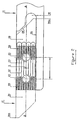
- the structure formed by the grooves 56 extends over a length L substantially equal to 21 distributed symmetrically with respect to the axis BB. It has a concave shape whose arrow f , exaggerated in the drawing to make it visible, is of the order of 0.002L.
- L is equal to 20 mm
- the deflection is advantageously 0.04 mm, which corresponds substantially to the accuracy of the flatness that can be guaranteed by sintering.
- the arrow is between 0 and 0.08 mm. In this way, it is possible to ensure perfect holding of the plate 12 on the tool holder 10.
- FIG. 2 shows how the grooves 32 come into contact with the grooves 56, for a wafer having the greatest concavity allowed in the tolerance, the contact areas 58 being hatched.
- the wafer is shown in dotted lines. It can be seen that these areas 58 extend from the ends of the grooves 32 to beyond the axes of the holes 20 and 22.
- the screws 14 apply their fixation force in a area where the wafer 12 is in contact with the tool holder 10.
- Such a provision is more advantageous than with a single screw, median, because it avoids excessive tension in the plate 12, which could cause it to break. This problem does not arise when the plate is very thick.
- this base 42 has a surface coming from sintering.
- a surface has a coefficient of significantly higher friction than a ground surface. It follows that, despite the fact that the wafer 12 is not in contact, over the entire surface of its base 42, with the seat 24, the rigidity of the tool is at least equal or greater than that obtained with a plate whose base is ground.
- the concavity could also be practiced on the tool holder 10 rather than on the wafer 12 whose base would then be substantially flat. That implies however more complex machining during the manufacture of the tool holder 10, the strawberry forming the grooves to have a path in an arc rather than linear.
- both the seat 24 and the base 42 are concave, the arrow f then being distributed between them two.
Landscapes
- Engineering & Computer Science (AREA)
- Mechanical Engineering (AREA)
- Cutting Tools, Boring Holders, And Turrets (AREA)
- Milling Processes (AREA)
- Auxiliary Devices For Machine Tools (AREA)
Description
- La figure 1 montre, en éclaté, un outil selon l'invention;
- La figure 2 représente le porte-outil en trait plein et la plaquette en pointillés, avec indication des zones de contact; et
- La figure 3 est une vue de côté du porte-outil et de la plaquette, éloignés l'un de l'autre.
Claims (7)
- Outil de coupe comportant un porte-outil (10) muni d'une assise (24), une plaquette d'usinage (12) en matériau fritté, munie d'une base (42) destinée à coopérer avec ladite assise (24) pour assurer le positionnement de la plaquette (12) sur le porte-outil (10), et des moyens de fixation (14) de la plaquette sur le porte-outil, dans lequel ladite assise (24) et ladite base (42) présentent chacune une structure à orientation longitudinale formée de sillons (32, 56) disposés parallèlement les uns aux autres et de formes complémentaires pour permettre l'engagement des structures l'une dans l'autre,
caractérisé en ce qu'au moins l'une desdites structures présente une concavité dans le sens longitudinal, de manière à ce qu'au moins les extrémités des sillons (32, 56) des deux structures soient en contact les unes avec les autres. - Outil selon la revendication 1, caractérisé en ce que la structure de la plaquette (12) présente ladite concavité.
- Outil selon la revendication 2, caractérisé en ce que ladite concavité est définie par une flèche (f) de l'ordre de 0,2% de la longueur (L) de ladite structure.
- Outil selon l'une des revendications 1 à 3, caractérisé en ce que la plaquette (12) et le porte-outil (10) comprennent chacun deux trous cylindriques (52, 54) dont les axes sont respectivement perpendiculaires à la base (42) et à l'assise (24) et alignés en référence auxdits sillons, et en ce que lesdits moyens de fixation sont formés par deux vis (14) engagées chacune dans l'un des trous de la plaquette (12) et du porte-outil (14).
- Outil selon la revendication 4, caractérisé en ce que les têtes (14a) des vis (14) sont de type conique et les trous (52, 54) que comporte la plaquette comprennent une portion conique (52b, 54b) agencée pour coopérer avec les têtes (14a) de vis, afin de positionner longitudinalement la plaquette (12) sur ledit porte-outil (10).
- Outil selon l'une des revendications 4 et 5, caractérisé en ce que les axes desdits trous (52, 54) sont distants l'un de l'autre d'une valeur (1) sensiblement égale à la moitié de la longueur (L) de la structure de ladite base (42) et disposés symétriquement par rapport au point médian de cette structure.
- Outil selon l'une des revendications 1 à 6, caractérisé en ce que la base (42) de ladite plaquette (12) présente une surface venue de frittage.
Priority Applications (2)
| Application Number | Priority Date | Filing Date | Title |
|---|---|---|---|
| DE60200551T DE60200551T3 (de) | 2001-03-13 | 2002-02-26 | Schneidwerkzeug |
| EP02711742A EP1368149B2 (fr) | 2001-03-13 | 2002-02-26 | Outil de coupe |
Applications Claiming Priority (4)
| Application Number | Priority Date | Filing Date | Title |
|---|---|---|---|
| EP01810254 | 2001-03-13 | ||
| EP01810254A EP1240961A1 (fr) | 2001-03-13 | 2001-03-13 | Outil de coupe |
| PCT/CH2002/000113 WO2002072300A1 (fr) | 2001-03-13 | 2002-02-26 | Outil de coupe |
| EP02711742A EP1368149B2 (fr) | 2001-03-13 | 2002-02-26 | Outil de coupe |
Publications (3)
| Publication Number | Publication Date |
|---|---|
| EP1368149A1 EP1368149A1 (fr) | 2003-12-10 |
| EP1368149B1 true EP1368149B1 (fr) | 2004-05-26 |
| EP1368149B2 EP1368149B2 (fr) | 2009-11-11 |
Family
ID=8183788
Family Applications (2)
| Application Number | Title | Priority Date | Filing Date |
|---|---|---|---|
| EP01810254A Withdrawn EP1240961A1 (fr) | 2001-03-13 | 2001-03-13 | Outil de coupe |
| EP02711742A Expired - Lifetime EP1368149B2 (fr) | 2001-03-13 | 2002-02-26 | Outil de coupe |
Family Applications Before (1)
| Application Number | Title | Priority Date | Filing Date |
|---|---|---|---|
| EP01810254A Withdrawn EP1240961A1 (fr) | 2001-03-13 | 2001-03-13 | Outil de coupe |
Country Status (6)
| Country | Link |
|---|---|
| EP (2) | EP1240961A1 (fr) |
| JP (1) | JP2004520949A (fr) |
| AT (1) | ATE267658T1 (fr) |
| DE (1) | DE60200551T3 (fr) |
| ES (1) | ES2220893T5 (fr) |
| WO (1) | WO2002072300A1 (fr) |
Cited By (1)
| Publication number | Priority date | Publication date | Assignee | Title |
|---|---|---|---|---|
| US10646926B2 (en) | 2016-02-29 | 2020-05-12 | Hartmetall-Werkzeugfabrik Paul Horn Gmbh | Cutting insert, tool holder, and tool for machining a workpiece |
Families Citing this family (8)
| Publication number | Priority date | Publication date | Assignee | Title |
|---|---|---|---|---|
| US6960049B2 (en) | 2002-06-25 | 2005-11-01 | Ngk Spark Plug Co., Ltd. | Insert, holder and cutting tool |
| EP1470878A1 (fr) * | 2003-04-22 | 2004-10-27 | Applitec Moutier S.A. | Outil de coupe à plaquette rapportée |
| SE526399C2 (sv) * | 2004-01-30 | 2005-09-06 | Sandvik Intellectual Property | Skärverktyg jämte del därtill med kopplingsytor med rillor samt tillverkningsförfarande för dessa |
| EP1661650B1 (fr) * | 2004-11-30 | 2009-01-28 | Applitec Moutier S.A. | Support d'outils |
| US7607867B2 (en) | 2006-12-15 | 2009-10-27 | Sandvik Intellectual Property Ab | Tooling insert with mating surface |
| US20170341150A1 (en) * | 2014-10-29 | 2017-11-30 | Illinois Tool Works Inc. | Interchangeable cutting inserts and methods associated with the same |
| US20160121406A1 (en) | 2014-10-29 | 2016-05-05 | Illinois Tool Works Inc. | Interchangeable cutting inserts and methods associated with the same |
| EP3677368B1 (fr) * | 2017-08-30 | 2023-09-20 | MOLDINO Tool Engineering, Ltd. | Insert de coupe et fraise à bout sphérique à bord de coupe remplaçable |
Family Cites Families (6)
| Publication number | Priority date | Publication date | Assignee | Title |
|---|---|---|---|---|
| FR2431897A1 (fr) * | 1978-07-25 | 1980-02-22 | Igman Sa | Plaquette rapportee pour outil de coupe rotatif |
| DE4140301A1 (de) * | 1991-12-06 | 1993-06-09 | Komet Stahlhalter- Und Werkzeugfabrik Robert Breuning Gmbh, 7122 Besigheim, De | Drehwerkzeug |
| SE505488C2 (sv) † | 1992-04-28 | 1997-09-08 | Sandvik Ab | Verktyg för avstickning eller liknande operationer |
| US5924826A (en) † | 1994-04-27 | 1999-07-20 | Sandvik Ab | Cutting insert mounted on holder by rib-and-groove coupling |
| SE511390C2 (sv) † | 1997-03-05 | 1999-09-20 | Sandvik Ab | Anordning vid fastspänning av skärplattor för skärande metallbearbetning |
| EP1189719B1 (fr) * | 1999-06-23 | 2003-04-16 | Applitec Moutier S.A. | Outil de coupe a plaquette rapportee |
-
2001
- 2001-03-13 EP EP01810254A patent/EP1240961A1/fr not_active Withdrawn
-
2002
- 2002-02-26 DE DE60200551T patent/DE60200551T3/de not_active Expired - Lifetime
- 2002-02-26 JP JP2002571251A patent/JP2004520949A/ja active Pending
- 2002-02-26 AT AT02711742T patent/ATE267658T1/de not_active IP Right Cessation
- 2002-02-26 EP EP02711742A patent/EP1368149B2/fr not_active Expired - Lifetime
- 2002-02-26 WO PCT/CH2002/000113 patent/WO2002072300A1/fr not_active Ceased
- 2002-02-26 ES ES02711742T patent/ES2220893T5/es not_active Expired - Lifetime
Cited By (1)
| Publication number | Priority date | Publication date | Assignee | Title |
|---|---|---|---|---|
| US10646926B2 (en) | 2016-02-29 | 2020-05-12 | Hartmetall-Werkzeugfabrik Paul Horn Gmbh | Cutting insert, tool holder, and tool for machining a workpiece |
Also Published As
| Publication number | Publication date |
|---|---|
| ES2220893T3 (es) | 2004-12-16 |
| WO2002072300A1 (fr) | 2002-09-19 |
| EP1368149A1 (fr) | 2003-12-10 |
| EP1368149B2 (fr) | 2009-11-11 |
| DE60200551T3 (de) | 2011-10-06 |
| DE60200551D1 (de) | 2004-07-01 |
| DE60200551T2 (de) | 2005-06-23 |
| JP2004520949A (ja) | 2004-07-15 |
| EP1240961A1 (fr) | 2002-09-18 |
| ATE267658T1 (de) | 2004-06-15 |
| ES2220893T5 (es) | 2010-04-05 |
Similar Documents
| Publication | Publication Date | Title |
|---|---|---|
| EP0210083B1 (fr) | Système de changement rapide de mors de serrage sur une machine-outil | |
| EP1368149B2 (fr) | Outil de coupe | |
| EP0090773B1 (fr) | Maillon de coupe pour chaîne de coupe | |
| EP2328704A1 (fr) | Outil de coupe plat et porte-outil associe | |
| FR2552000A1 (fr) | Outil a aleser possedant une tete a deux porte-plaquettes reglables pour varier le diametre | |
| FR2909574A1 (fr) | Mandrin de serrage. | |
| FR2488537A1 (fr) | Outil de fraisage pour fraiser des gorges ou rainures, en particulier des chemins de roulement de billes pour des joints homocinetiques | |
| EP1189719B1 (fr) | Outil de coupe a plaquette rapportee | |
| EP0589787B1 (fr) | Positionneur pour coupe des carreaux en diagonale | |
| EP0587478B1 (fr) | Outil à taillant rapporté pour machines à graver | |
| FR2615769A1 (fr) | Dispositif de reglage d'un outil de coupe | |
| EP1617963B1 (fr) | Outil de coupe a plaquette rapportee | |
| FR2795013A1 (fr) | Outil de centrage et de serrage | |
| EP0216707B1 (fr) | Machine à couper les carreaux, notamment de faience | |
| EP1648640B1 (fr) | Outil de coupe | |
| EP1424151A1 (fr) | Plaquette de coupe | |
| FR2606453A1 (fr) | Couteau de sole pour rabot d'abattage d'exploitation miniere | |
| FR2551684A1 (fr) | Ensemble de poste d'outils pour machines-outils | |
| FR2713118A1 (fr) | Dispositif pour le finissage d'alésages. | |
| FR2795665A1 (fr) | Outil de coupe a plaquette rapportee | |
| CH642882A5 (fr) | Outil de tournage. | |
| EP1858664B1 (fr) | Outil et machine pour operations d'usinage presentant un risque de travail à rebours | |
| WO1995003908A1 (fr) | Outil a plaquette amovible pour usinage par enlevement de copeaux | |
| FR2878772A1 (fr) | Plaquette de coupe pour outil de percage rotatif | |
| FR2589943A1 (fr) | Fleuret pour le forage roto-percutant |
Legal Events
| Date | Code | Title | Description |
|---|---|---|---|
| PUAI | Public reference made under article 153(3) epc to a published international application that has entered the european phase |
Free format text: ORIGINAL CODE: 0009012 |
|
| GRAP | Despatch of communication of intention to grant a patent |
Free format text: ORIGINAL CODE: EPIDOSNIGR1 |
|
| 17P | Request for examination filed |
Effective date: 20030902 |
|
| AK | Designated contracting states |
Kind code of ref document: A1 Designated state(s): AT BE CH CY DE DK ES FI FR GB GR IE IT LI LU MC NL PT SE TR |
|
| AX | Request for extension of the european patent |
Extension state: AL LT LV MK RO SI |
|
| TPAC | Observations filed by third parties |
Free format text: ORIGINAL CODE: EPIDOSNTIPA |
|
| GRAS | Grant fee paid |
Free format text: ORIGINAL CODE: EPIDOSNIGR3 |
|
| GRAA | (expected) grant |
Free format text: ORIGINAL CODE: 0009210 |
|
| AK | Designated contracting states |
Kind code of ref document: B1 Designated state(s): AT BE CH CY DE DK ES FI FR GB GR IE IT LI LU MC NL PT SE TR |
|
| AX | Request for extension of the european patent |
Extension state: AL LT LV MK RO SI |
|
| PG25 | Lapsed in a contracting state [announced via postgrant information from national office to epo] |
Ref country code: AT Free format text: LAPSE BECAUSE OF FAILURE TO SUBMIT A TRANSLATION OF THE DESCRIPTION OR TO PAY THE FEE WITHIN THE PRESCRIBED TIME-LIMIT Effective date: 20040526 Ref country code: FI Free format text: LAPSE BECAUSE OF FAILURE TO SUBMIT A TRANSLATION OF THE DESCRIPTION OR TO PAY THE FEE WITHIN THE PRESCRIBED TIME-LIMIT Effective date: 20040526 Ref country code: IE Free format text: LAPSE BECAUSE OF FAILURE TO SUBMIT A TRANSLATION OF THE DESCRIPTION OR TO PAY THE FEE WITHIN THE PRESCRIBED TIME-LIMIT Effective date: 20040526 Ref country code: NL Free format text: LAPSE BECAUSE OF FAILURE TO SUBMIT A TRANSLATION OF THE DESCRIPTION OR TO PAY THE FEE WITHIN THE PRESCRIBED TIME-LIMIT Effective date: 20040526 Ref country code: TR Free format text: LAPSE BECAUSE OF FAILURE TO SUBMIT A TRANSLATION OF THE DESCRIPTION OR TO PAY THE FEE WITHIN THE PRESCRIBED TIME-LIMIT Effective date: 20040526 |
|
| REG | Reference to a national code |
Ref country code: GB Ref legal event code: FG4D Free format text: NOT ENGLISH |
|
| REG | Reference to a national code |
Ref country code: CH Ref legal event code: EP |
|
| REG | Reference to a national code |
Ref country code: IE Ref legal event code: FG4D Free format text: FRENCH |
|
| REF | Corresponds to: |
Ref document number: 60200551 Country of ref document: DE Date of ref document: 20040701 Kind code of ref document: P |
|
| REG | Reference to a national code |
Ref country code: CH Ref legal event code: NV Representative=s name: GLN GRESSET & LAESSER NEUCHATEL CABINET DE CONSEIL |
|
| PG25 | Lapsed in a contracting state [announced via postgrant information from national office to epo] |
Ref country code: SE Free format text: LAPSE BECAUSE OF FAILURE TO SUBMIT A TRANSLATION OF THE DESCRIPTION OR TO PAY THE FEE WITHIN THE PRESCRIBED TIME-LIMIT Effective date: 20040826 Ref country code: GR Free format text: LAPSE BECAUSE OF FAILURE TO SUBMIT A TRANSLATION OF THE DESCRIPTION OR TO PAY THE FEE WITHIN THE PRESCRIBED TIME-LIMIT Effective date: 20040826 Ref country code: DK Free format text: LAPSE BECAUSE OF FAILURE TO SUBMIT A TRANSLATION OF THE DESCRIPTION OR TO PAY THE FEE WITHIN THE PRESCRIBED TIME-LIMIT Effective date: 20040826 |
|
| GBT | Gb: translation of ep patent filed (gb section 77(6)(a)/1977) |
Effective date: 20040826 |
|
| LTIE | Lt: invalidation of european patent or patent extension |
Effective date: 20040526 |
|
| NLV1 | Nl: lapsed or annulled due to failure to fulfill the requirements of art. 29p and 29m of the patents act | ||
| REG | Reference to a national code |
Ref country code: ES Ref legal event code: FG2A Ref document number: 2220893 Country of ref document: ES Kind code of ref document: T3 |
|
| REG | Reference to a national code |
Ref country code: IE Ref legal event code: FD4D |
|
| PG25 | Lapsed in a contracting state [announced via postgrant information from national office to epo] |
Ref country code: CY Free format text: LAPSE BECAUSE OF FAILURE TO SUBMIT A TRANSLATION OF THE DESCRIPTION OR TO PAY THE FEE WITHIN THE PRESCRIBED TIME-LIMIT Effective date: 20050226 Ref country code: LU Free format text: LAPSE BECAUSE OF NON-PAYMENT OF DUE FEES Effective date: 20050226 |
|
| PG25 | Lapsed in a contracting state [announced via postgrant information from national office to epo] |
Ref country code: MC Free format text: LAPSE BECAUSE OF NON-PAYMENT OF DUE FEES Effective date: 20050228 Ref country code: BE Free format text: LAPSE BECAUSE OF NON-PAYMENT OF DUE FEES Effective date: 20050228 |
|
| PLAQ | Examination of admissibility of opposition: information related to despatch of communication + time limit deleted |
Free format text: ORIGINAL CODE: EPIDOSDOPE2 |
|
| PLBQ | Unpublished change to opponent data |
Free format text: ORIGINAL CODE: EPIDOS OPPO |
|
| PLBI | Opposition filed |
Free format text: ORIGINAL CODE: 0009260 |
|
| PLAQ | Examination of admissibility of opposition: information related to despatch of communication + time limit deleted |
Free format text: ORIGINAL CODE: EPIDOSDOPE2 |
|
| PLAR | Examination of admissibility of opposition: information related to receipt of reply deleted |
Free format text: ORIGINAL CODE: EPIDOSDOPE4 |
|
| PLBQ | Unpublished change to opponent data |
Free format text: ORIGINAL CODE: EPIDOS OPPO |
|
| PLAQ | Examination of admissibility of opposition: information related to despatch of communication + time limit deleted |
Free format text: ORIGINAL CODE: EPIDOSDOPE2 |
|
| PLAR | Examination of admissibility of opposition: information related to receipt of reply deleted |
Free format text: ORIGINAL CODE: EPIDOSDOPE4 |
|
| PLBQ | Unpublished change to opponent data |
Free format text: ORIGINAL CODE: EPIDOS OPPO |
|
| PLAB | Opposition data, opponent's data or that of the opponent's representative modified |
Free format text: ORIGINAL CODE: 0009299OPPO |
|
| PLAX | Notice of opposition and request to file observation + time limit sent |
Free format text: ORIGINAL CODE: EPIDOSNOBS2 |
|
| 26 | Opposition filed |
Opponent name: INTELLECTUAL PROPERTY SERVICES (IPS) Effective date: 20050225 |
|
| R26 | Opposition filed (corrected) |
Opponent name: INTELLECTUAL PROPERTY SERVICES (IPS) Effective date: 20050225 |
|
| PLBB | Reply of patent proprietor to notice(s) of opposition received |
Free format text: ORIGINAL CODE: EPIDOSNOBS3 |
|
| BERE | Be: lapsed |
Owner name: S.A. *APPLITEC MOUTIER Effective date: 20050228 |
|
| PG25 | Lapsed in a contracting state [announced via postgrant information from national office to epo] |
Ref country code: FR Free format text: LAPSE BECAUSE OF NON-PAYMENT OF DUE FEES Effective date: 20051031 |
|
| REG | Reference to a national code |
Ref country code: FR Ref legal event code: ST Effective date: 20051031 |
|
| REG | Reference to a national code |
Ref country code: FR Ref legal event code: D3 |
|
| APAH | Appeal reference modified |
Free format text: ORIGINAL CODE: EPIDOSCREFNO |
|
| APBP | Date of receipt of notice of appeal recorded |
Free format text: ORIGINAL CODE: EPIDOSNNOA2O |
|
| APBP | Date of receipt of notice of appeal recorded |
Free format text: ORIGINAL CODE: EPIDOSNNOA2O |
|
| APBQ | Date of receipt of statement of grounds of appeal recorded |
Free format text: ORIGINAL CODE: EPIDOSNNOA3O |
|
| APBQ | Date of receipt of statement of grounds of appeal recorded |
Free format text: ORIGINAL CODE: EPIDOSNNOA3O |
|
| BERE | Be: lapsed |
Owner name: S.A. *APPLITEC MOUTIER Effective date: 20050228 |
|
| PG25 | Lapsed in a contracting state [announced via postgrant information from national office to epo] |
Ref country code: PT Free format text: LAPSE BECAUSE OF NON-PAYMENT OF DUE FEES Effective date: 20041026 |
|
| PLAB | Opposition data, opponent's data or that of the opponent's representative modified |
Free format text: ORIGINAL CODE: 0009299OPPO |
|
| APBU | Appeal procedure closed |
Free format text: ORIGINAL CODE: EPIDOSNNOA9O |
|
| PUAH | Patent maintained in amended form |
Free format text: ORIGINAL CODE: 0009272 |
|
| STAA | Information on the status of an ep patent application or granted ep patent |
Free format text: STATUS: PATENT MAINTAINED AS AMENDED |
|
| 27A | Patent maintained in amended form |
Effective date: 20091111 |
|
| AK | Designated contracting states |
Kind code of ref document: B2 Designated state(s): AT BE CH CY DE DK ES FI FR GB GR IE IT LI LU MC NL PT SE TR |
|
| REG | Reference to a national code |
Ref country code: CH Ref legal event code: AEN Free format text: BREVET MAINTENU DANS UNE FORME MODIFIEE |
|
| REG | Reference to a national code |
Ref country code: ES Ref legal event code: DC2A Date of ref document: 20100127 Kind code of ref document: T5 |
|
| PG25 | Lapsed in a contracting state [announced via postgrant information from national office to epo] |
Ref country code: DE Free format text: LAPSE BECAUSE OF FAILURE TO SUBMIT A TRANSLATION OF THE DESCRIPTION OR TO PAY THE FEE WITHIN THE PRESCRIBED TIME-LIMIT Effective date: 20100212 |
|
| REG | Reference to a national code |
Ref country code: DE Ref legal event code: R074 Ref document number: 60200551 Country of ref document: DE Effective date: 20110502 |
|
| PGRI | Patent reinstated in contracting state [announced from national office to epo] |
Ref country code: DE Effective date: 20110502 |
|
| REG | Reference to a national code |
Ref country code: CH Ref legal event code: PFA Owner name: APPLITEC MOUTIER S.A., CH Free format text: FORMER OWNER: APPLITEC MOUTIER S.A., CH |
|
| PGRI | Patent reinstated in contracting state [announced from national office to epo] |
Ref country code: DE Effective date: 20110502 |
|
| PGRI | Patent reinstated in contracting state [announced from national office to epo] |
Ref country code: DE Effective date: 20110502 |
|
| REG | Reference to a national code |
Ref country code: FR Ref legal event code: PLFP Year of fee payment: 15 |
|
| REG | Reference to a national code |
Ref country code: CH Ref legal event code: PFA Owner name: APPLITEC MOUTIER S.A., CH Free format text: FORMER OWNER: APPLITEC MOUTIER S.A., CH |
|
| REG | Reference to a national code |
Ref country code: FR Ref legal event code: PLFP Year of fee payment: 16 |
|
| REG | Reference to a national code |
Ref country code: FR Ref legal event code: PLFP Year of fee payment: 17 |
|
| REG | Reference to a national code |
Ref country code: CH Ref legal event code: NV Representative=s name: BOVARD SA NEUCHATEL CONSEILS EN PROPRIETE INTE, CH |
|
| PG25 | Lapsed in a contracting state [announced via postgrant information from national office to epo] |
Ref country code: FR Free format text: LAPSE BECAUSE OF NON-PAYMENT OF DUE FEES Effective date: 20051031 |
|
| PGRI | Patent reinstated in contracting state [announced from national office to epo] |
Ref country code: FR Effective date: 20060203 |
|
| PGFP | Annual fee paid to national office [announced via postgrant information from national office to epo] |
Ref country code: FR Payment date: 20210224 Year of fee payment: 20 Ref country code: CH Payment date: 20210219 Year of fee payment: 20 Ref country code: IT Payment date: 20210218 Year of fee payment: 20 |
|
| PGFP | Annual fee paid to national office [announced via postgrant information from national office to epo] |
Ref country code: DE Payment date: 20210217 Year of fee payment: 20 Ref country code: GB Payment date: 20210219 Year of fee payment: 20 |
|
| PGFP | Annual fee paid to national office [announced via postgrant information from national office to epo] |
Ref country code: ES Payment date: 20210421 Year of fee payment: 20 |
|
| REG | Reference to a national code |
Ref country code: DE Ref legal event code: R071 Ref document number: 60200551 Country of ref document: DE |
|
| REG | Reference to a national code |
Ref country code: CH Ref legal event code: PL |
|
| REG | Reference to a national code |
Ref country code: GB Ref legal event code: PE20 Expiry date: 20220225 |
|
| PG25 | Lapsed in a contracting state [announced via postgrant information from national office to epo] |
Ref country code: GB Free format text: LAPSE BECAUSE OF EXPIRATION OF PROTECTION Effective date: 20220225 |
|
| REG | Reference to a national code |
Ref country code: ES Ref legal event code: FD2A Effective date: 20220602 |
|
| PG25 | Lapsed in a contracting state [announced via postgrant information from national office to epo] |
Ref country code: ES Free format text: LAPSE BECAUSE OF EXPIRATION OF PROTECTION Effective date: 20220227 |
|
| P01 | Opt-out of the competence of the unified patent court (upc) registered |
Effective date: 20230530 |