EP1368210B1 - Appui-tete de securite destine a un vehicule a moteur - Google Patents
Appui-tete de securite destine a un vehicule a moteur Download PDFInfo
- Publication number
- EP1368210B1 EP1368210B1 EP02705648A EP02705648A EP1368210B1 EP 1368210 B1 EP1368210 B1 EP 1368210B1 EP 02705648 A EP02705648 A EP 02705648A EP 02705648 A EP02705648 A EP 02705648A EP 1368210 B1 EP1368210 B1 EP 1368210B1
- Authority
- EP
- European Patent Office
- Prior art keywords
- rest
- pressure plate
- seat
- head
- depending
- Prior art date
- Legal status (The legal status is an assumption and is not a legal conclusion. Google has not performed a legal analysis and makes no representation as to the accuracy of the status listed.)
- Expired - Lifetime
Links
- 208000021567 Whiplash injury Diseases 0.000 description 5
- 206010071366 Post-traumatic neck syndrome Diseases 0.000 description 2
- 210000003127 knee Anatomy 0.000 description 1
Images


Classifications
-
- B—PERFORMING OPERATIONS; TRANSPORTING
- B60—VEHICLES IN GENERAL
- B60N—SEATS SPECIALLY ADAPTED FOR VEHICLES; VEHICLE PASSENGER ACCOMMODATION NOT OTHERWISE PROVIDED FOR
- B60N2/00—Seats specially adapted for vehicles; Arrangement or mounting of seats in vehicles
- B60N2/80—Head-rests
- B60N2/806—Head-rests movable or adjustable
- B60N2/838—Tiltable
- B60N2/853—Tiltable characterised by their adjusting mechanisms, e.g. electric motors
-
- B—PERFORMING OPERATIONS; TRANSPORTING
- B60—VEHICLES IN GENERAL
- B60N—SEATS SPECIALLY ADAPTED FOR VEHICLES; VEHICLE PASSENGER ACCOMMODATION NOT OTHERWISE PROVIDED FOR
- B60N2/00—Seats specially adapted for vehicles; Arrangement or mounting of seats in vehicles
- B60N2/80—Head-rests
- B60N2/888—Head-rests with arrangements for protecting against abnormal g-forces, e.g. by displacement of the head-rest
Definitions
- THE PRESENT INVENTION relates to a safety arrangement, and more particularly relates to a safety arrangement incorporated in a vehicle seat.
- a seat which is provided with a head-rest mounted on the back of the seat, the head-rests being adapted to move forwardly in the event that a rear impact should occur to provide protection for the occupant of the seat in order to minimise, or obviate whiplash injuries.
- a head-rest may be termed an "active" head-rest.
- This prior proposed arrangement is intended for use in the front seat of a motor vehicle.
- the front seat of a motor vehicle has a back-rest formed from an inverted "U"-shaped frame, with appropriate springing and padding filling the area between the parallel arms of the frame.
- both the forward facing side and the rearward facing side of the back-rest are made to be soft and flexible so that the seat is not only comfortable for a person sitting in the seat, but also is not uncomfortable for the knees of a person sitting in the seat behind.
- the pressure plate can move rearwardly relative to the inverted "U"-shaped frame when a rear impact occurs.
- the rear part of the back-rest of a rear seat is constituted by a rigid panel.
- the rear part of the back-rest of the rear seat forms an upright wall defining part of the boot or trunk. This wall must be sufficiently strong to prevent any luggage present in the boot or trunk from entering the passenger compartment in a frontal impact situation.
- the back-rest of the rear seat may fold downwardly, and then the panel at the back of the back-rest forms part of a load-bearing platform.
- the present invention seeks to provide an improved safety arrangement.
- a safety arrangement for a motor vehicle seat comprising a head-rest, means to mount the head-rest for pivotal movement about a predetermined horizontal axis adjacent the upper part of the back-rest of the seat, and depending means adapted to extend downwardly within the back-rest of the seat beneath the predetermined axis, and which carry a pressure plate to be located within the back-rest at a position behind the torso of an occupant of the seat, so that pressure applied to the pressure plate will cause the head-rest to move, characterised by the rear of the back-rest having a rigid panel and the pressure plate being pivotally connected to the depending means. In this way, continuing pressure applied to the pressure plate after the pressure plate strikes the rigid panel causes the pressure plate to pivot relative to the depending means.
- the depending means comprise parallel arms.
- the pressure plate is provided with an integral locating element extending upwardly above the axis about which the pressure plate is pivotally connected to the depending means, the locating element being releasably connected to the depending means.
- the locating element is connected to the depending means by means of at least one spring clip.
- the locating element is connected to the depending means by means of at least one frangible element.
- a locating element is arranged in association with the pressure plate and the depending means in a position above the axis about which the pressure plate is pivotally connected to the depending means.
- the locating element is deformable.
- the means to mount the head-rest comprise a substantially horizontal bar adapted to be mounted, by means of bearings, on a frame within the back-rest of the seat, the axis of the horizontal bar being the said predetermined axis, the head-rest being connected to the bar.
- the depending means are connected to and depend from the bar.
- a head-rest is provided on a vehicle seat, and the head-rest is adapted to move forwardly when there is a rear impact to reduce or obviate whiplash injuries.
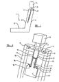
- a vehicle seat 1 intended for use in a rear seat, comprises a squab 2 and back-rest 3.
- the rear face of the back-rest 3 is in the form of a rigid panel 4.
- the back-rest 3 is associated with a head-rest 5.
- the head-rest 5 is initially mounted in position above the back-rest of the seat and is supported by a pair of parallel support arms 6.
- the parallel support arms 6 are connected to a pivotally mounted horizontal bar 7.
- the pivotally mounted bar 7 has opposed ends thereof supported in bearings 8 which are mounted on a horizontal frame member 9 located in the back-rest of the seat, the horizontal frame member 9, together with two vertical parallel arm members 10, 11, forming a substantially rigid inverted "U"-shaped frame contained within the seat.
- Two further parallel arms 12 are also connected to the horizontal bar 7, the arms 12 depending within the back-rest of the seat.
- the lower ends of the arms 12 carry a pressure plate 13.
- the pressure plate 13 is provided with upwardly extending lugs 14, 15, which each receive an outwardly directed pivot pin 16, 17, carried at the lower ends of the arms 12.
- the pressure plate can thus pivot about the axis of the co-aligned pins 16, 17.
- the pressure plate can only pivot in one pivotal direction from the initial position shown in Figure 1. Pivotal movement in the opposite direction is prevented, for example by a stop, a ratchet or equivalent device.
- the pressure plate 13 incorporates an upwardly directed locating arm 18, which extends upwardly between the parallel arms 12.
- the upper end of the locating arm 18 is releasably connected to the arms 12 by releasable catches 19, 20, which may be spring catches, or which may be catches constituted by frangible elements adapted to break when subjected to a predetermined force.
- releasable catches 19, 20 which may be spring catches, or which may be catches constituted by frangible elements adapted to break when subjected to a predetermined force.
- One or more springs, or other resilient means may be provided to bias the head-rest to the "initial" position shown in Figure 1.
- the head-rest when the seat is in ordinary use, the head-rest will be substantially stationary. However, when a vehicle in which the seat is mounted is subjected to a rear impact, the torso of an occupant of the seat will move so that the torso is effectively forced into the back-rest 3 of the seat. The torso of the occupant will then engage the pressure plate 13, and the combination of the pressure plate 13, the parallel arms 12, the horizontal bar 7, the arm 6 and the head-rest 5, will pivot about the axis of the bar 7, the ends of the rod 7 rotating within the bearings 8. The head-rest 5 will thus begin to move forwardly.
- the lower-most edge of the pressure plate 13 will strike the rigid panel 4 provided at the rear of the back-rest 3. Continuing pressure applied to the pressure plate 13 by the torso of the occupant of the seat will cause the clips 19, 20 to be released so that the upper part of the locating arm 18 is no longer connected to the depending arms 12. The pressure plate is then free to rotate about the axis of the co-aligned pins 16, 17, in its single direction of pivotal movement.
- a vehicle seat 1 intended for use in a rear seat with the safety arrangement in accordance with an alternative embodiment of the invention has a pressure plate 13' pivotally connected to lower ends of the depending arms 12 and carried at the lower ends of the depending arms 12.
- the pressure plate 13' extends upwardly and downwardly from the pivoting axis.
- the pressure plate is in ordinary use held in a position relative the depending arms 12 by deformable bands 21.
- the torso will then engage the pressure plate 13' and the combination of the pressure plate 13', the parallel arms 12, the horizontal bar 7, the arm 6 and the head rest 5 will pivot about the axis of the bar 7 such that the head rest 5 will begin to move forwardly. Also for this embodiment the lower-most end of the pressure plate 13' will strike the rigid panel 4 at the rear of the back-rest 3. Continuing pressure applied to the pressure plate 13' by the torso of the occupant of the seat will cause the bands 21 to deform so that the upper part of the pressure plate will start to rotate about the pivoting axis. As can be seen from figure 5 and figure 6, this means that the pressure plate 13' will pivot about the pivoting axis.
- the head-rest and the depending parallel arms are mounted on a horizontal rotatable bar which extends between the two vertical parallel arm members that form the frame in the back of the seat.
- the rotatable bar itself forms the transverse part of the inverted "U" shaped frame.
Landscapes
- Engineering & Computer Science (AREA)
- Aviation & Aerospace Engineering (AREA)
- Transportation (AREA)
- Mechanical Engineering (AREA)
- Seats For Vehicles (AREA)
- Chair Legs, Seat Parts, And Backrests (AREA)
Claims (9)
- Un dispositif de sécurité pour un véhicule à moteur, le dispositif de sécurité comprenant un appui-tête (5), des moyens pour monter l'appui-tête (5) pour permettre un mouvement pivotant autour d'un axe (7) horizontal prédéterminé, adjacent à la partie supérieure du dossier (3) du siège, et des moyens dépendants (12), adaptés pour s'étendre vers le bas à l'intérieur du dossier (3) du siège, au-dessous de l'axe (7) prédéterminé, et portant une plaque de pressage (13), devant être placée à l'intérieur du dossier (3) en une position située derrière le torse d'un occupant du siège, de manière qu'une pression, appliquée à la plaque de pressage (13), provoque le déplacement de l'appui-tête (5), caractérisé par le fait que l'arrière du dossier (3) comprend un panneau (4) rigide et la plaque de pressage (13) étant reliée à pivotement aux moyens dépendants (12).
- Un dispositif selon la revendication 1, dans lequel les moyens dépendants comprennent des bras (12) parallèles.
- Un dispositif selon la revendication 1 ou selon la revendication 2, dans lequel la plaque de pressage (13) est munie d'un élément de positionnement (18) monobloc, s'étendant vers le haut, au-dessus de l'axe autour duquel la plaque de pressage (13) est reliée à pivotement aux moyens dépendants (12), l'élément de positionnement (18) étant relié de façon désolidarisable aux moyens dépendants (12).
- Un dispositif selon la revendication 3, dans lequel l'élément de positionnement (18) est relié aux moyens dépendants (12), à l'aide d'au moins une attache élastique (19,20).
- Un dispositif selon la revendication 3, dans lequel l'élément de positionnement (18) est relié aux moyens dépendants (12) à l'aide d'au moins un élément fracturable.
- Un dispositif selon la revendication 1 ou 2, dans lequel un élément de positionnement (21) est agencé en association avec la plaque de pressage (13) et les moyens dépendants (12), en une position située au-dessus de l'axe autour duquel la plaque de pressage (13) est reliée à pivotement aux moyens dépendants (12).
- Un dispositif selon la revendication 6, dans lequel l'élément de positionnement (21) est déformable.
- Un dispositif selon l'une quelconque des revendications précédentes, dans lequel les moyens de montage de l'appui-tête (5) comprennent une barre (7) sensiblement horizontale, adaptée pour être montée, au moyen de paliers (8), sur un cadre situé à l'intérieur du dossier du siège, l'axe de la barre horizontale (7) étant ledit axe prédéterminé, l'appui-tête (5) étant relié à la barre (7).
- Un dispositif selon la revendication 6, dans lequel les moyens dépendants (12) sont reliés à et dépendent de la barre (7).
Applications Claiming Priority (3)
| Application Number | Priority Date | Filing Date | Title |
|---|---|---|---|
| GB0106470A GB2373177B (en) | 2001-03-15 | 2001-03-15 | Improvements in or relating to a safety arrangement |
| GB0106470 | 2001-03-15 | ||
| PCT/SE2002/000434 WO2002074579A1 (fr) | 2001-03-15 | 2002-03-11 | Appui-tete de securite destine a un vehicule a moteur |
Publications (2)
| Publication Number | Publication Date |
|---|---|
| EP1368210A1 EP1368210A1 (fr) | 2003-12-10 |
| EP1368210B1 true EP1368210B1 (fr) | 2005-12-14 |
Family
ID=9910789
Family Applications (1)
| Application Number | Title | Priority Date | Filing Date |
|---|---|---|---|
| EP02705648A Expired - Lifetime EP1368210B1 (fr) | 2001-03-15 | 2002-03-11 | Appui-tete de securite destine a un vehicule a moteur |
Country Status (6)
| Country | Link |
|---|---|
| US (1) | US6983996B2 (fr) |
| EP (1) | EP1368210B1 (fr) |
| JP (1) | JP4008820B2 (fr) |
| DE (1) | DE60207997T2 (fr) |
| GB (1) | GB2373177B (fr) |
| WO (1) | WO2002074579A1 (fr) |
Families Citing this family (23)
| Publication number | Priority date | Publication date | Assignee | Title |
|---|---|---|---|---|
| US7604080B2 (en) * | 1997-12-17 | 2009-10-20 | Automotive Technologies International, Inc. | Rear impact occupant protection apparatus and method |
| GB2395114B (en) * | 2002-11-08 | 2005-04-13 | Autoliv Dev | Improvements in or relating to a head-rest arrangement |
| US7134716B2 (en) * | 2002-11-27 | 2006-11-14 | Lear Corporation | Headrest seat-back arrangement |
| GB2403137B (en) | 2003-06-24 | 2006-03-08 | Autoliv Dev | Improvements in or relating to a vehicle seat |
| US7644987B2 (en) | 2004-09-27 | 2010-01-12 | Lear Corporation | Vehicle seat having active head restraint system |
| US7185950B2 (en) | 2004-12-28 | 2007-03-06 | Fisher Dynamics Corporation | Head restraint system |
| GB2424363B (en) * | 2005-03-24 | 2008-07-16 | Autoliv Dev | Active headrest with lock mechanism |
| JP2006298244A (ja) * | 2005-04-22 | 2006-11-02 | Nissan Motor Co Ltd | アクティブヘッドレスト構造 |
| DE102006006518B3 (de) * | 2006-02-10 | 2007-07-19 | Johnson Controls Gmbh | Aktuierungseinrichtung und Sitz, insbesondere Kraftfahrzeugsitz |
| US7401852B2 (en) * | 2006-06-08 | 2008-07-22 | Lear Corporation | Actuatable back panel for a vehicle seat |
| US7621598B2 (en) * | 2006-10-03 | 2009-11-24 | Lear Corporation | Adjustable head restraint for a vehicle seat |
| US7455357B2 (en) * | 2006-10-04 | 2008-11-25 | Lear Corporation | Active head restraint system for a vehicle seat |
| US7677659B2 (en) * | 2007-02-06 | 2010-03-16 | Lear Corporation | Active head restraint systems for vehicle seats |
| US7850235B2 (en) * | 2007-10-17 | 2010-12-14 | Lear Corporation | Active head restraint system with actuating system for a vehicle seat |
| US8052211B2 (en) | 2007-10-29 | 2011-11-08 | University Of Delaware | Anti-whiplash vehicle system with active head restraint |
| US8690238B2 (en) * | 2008-01-14 | 2014-04-08 | Ford Global Technologies, Llc | Active head restraint system for an automotive vehicle seat |
| US8205941B2 (en) * | 2008-07-30 | 2012-06-26 | Trw Vehicle Safety Systems Inc. | Active head restraint for a vehicle seat |
| US7959224B2 (en) * | 2009-03-17 | 2011-06-14 | Ford Global Technologies, Llc | Active head restraint having multiple horizontal pivot points |
| DE102009043113A1 (de) * | 2009-09-25 | 2011-03-31 | Daimler Ag | Verfahren zum Schützen eines Fahrzeuginsassen in einem Fahrzeugsitz eines Fahrzeugs |
| KR101389067B1 (ko) * | 2012-05-02 | 2014-04-23 | 경북대학교 산학협력단 | 차량좌석 안전벨트 시스템 |
| US10059234B2 (en) * | 2016-06-10 | 2018-08-28 | Ford Global Technologies, Llc | Vehicle seatback |
| JP7078011B2 (ja) * | 2019-05-08 | 2022-05-31 | トヨタ自動車株式会社 | 車両用シート |
| US12606069B2 (en) | 2024-06-21 | 2026-04-21 | Alyse Laudonio | Automotive headrest with emergency adaptations |
Family Cites Families (17)
| Publication number | Priority date | Publication date | Assignee | Title |
|---|---|---|---|---|
| US3802737A (en) * | 1972-07-07 | 1974-04-09 | Heizer K | Safety seat, particularly for automotive vehicles |
| US5378043A (en) * | 1993-06-01 | 1995-01-03 | General Motors Corporation | Vehicle pivotal headrest |
| DE29601479U1 (de) * | 1996-01-29 | 1996-05-30 | Trw Occupant Restraint Systems Gmbh, 73551 Alfdorf | Fahrzeugsitz |
| GB2316862A (en) * | 1996-09-05 | 1998-03-11 | Autoliv Dev | Vehicle seat headrest |
| SE510735C2 (sv) | 1996-09-06 | 1999-06-21 | Saab Automobile | Fordonsstol försedd med ett nackstöd |
| GB2316863B (en) * | 1996-09-06 | 2000-07-26 | Autoliv Dev | Improvements in or relating to a safety seat |
| GB2318045B (en) * | 1996-10-09 | 2000-08-09 | Delphi Automotive Systems Gmbh | Vehicle seat and headrest arrangement |
| DE19643977C2 (de) * | 1996-10-31 | 2000-03-30 | Keiper Gmbh & Co | Fahrzeugsitz mit Multifunktionslehne |
| US5884968A (en) * | 1997-01-23 | 1999-03-23 | Lear Corporation | Seat assembly with pneumatically adjustable contour and energy absorption |
| US5829838A (en) * | 1997-08-11 | 1998-11-03 | General Motors Corporation | Integral automotive seatback and headrest cushion |
| DE19753540A1 (de) * | 1997-12-03 | 1999-06-10 | Ewald Witte Gmbh & Co Kg | Kopfstütze, insbesondere in Kraftfahrzeugen |
| US5927804A (en) * | 1998-02-11 | 1999-07-27 | Trw Inc. | Vehicle occupant protection apparatus |
| US6033017A (en) * | 1998-04-09 | 2000-03-07 | Trw Inc. | Vehicle occupant protection apparatus |
| US5938279A (en) * | 1998-05-01 | 1999-08-17 | Lear Corporation | Dynamic vehicle head restraint assembly |
| US6604788B1 (en) * | 1998-12-14 | 2003-08-12 | Lear Corporation | Vehicle pivotal headrest |
| JP3750422B2 (ja) * | 1999-06-18 | 2006-03-01 | 日産自動車株式会社 | 車両用シート |
| DE19961618C1 (de) | 1999-12-21 | 2001-04-12 | Daimler Chrysler Ag | Rückenlehne für einen Fahrzeugsitz |
-
2001
- 2001-03-15 GB GB0106470A patent/GB2373177B/en not_active Expired - Fee Related
-
2002
- 2002-03-11 US US10/471,064 patent/US6983996B2/en not_active Expired - Lifetime
- 2002-03-11 DE DE60207997T patent/DE60207997T2/de not_active Expired - Lifetime
- 2002-03-11 EP EP02705648A patent/EP1368210B1/fr not_active Expired - Lifetime
- 2002-03-11 JP JP2002573262A patent/JP4008820B2/ja not_active Expired - Fee Related
- 2002-03-11 WO PCT/SE2002/000434 patent/WO2002074579A1/fr not_active Ceased
Also Published As
| Publication number | Publication date |
|---|---|
| US6983996B2 (en) | 2006-01-10 |
| JP4008820B2 (ja) | 2007-11-14 |
| JP2004529802A (ja) | 2004-09-30 |
| GB0106470D0 (en) | 2001-05-02 |
| GB2373177A (en) | 2002-09-18 |
| EP1368210A1 (fr) | 2003-12-10 |
| US20040245833A1 (en) | 2004-12-09 |
| GB2373177B (en) | 2004-04-28 |
| DE60207997D1 (de) | 2006-01-19 |
| WO2002074579A1 (fr) | 2002-09-26 |
| DE60207997T2 (de) | 2006-07-06 |
Similar Documents
| Publication | Publication Date | Title |
|---|---|---|
| US6983996B2 (en) | Safety headrest for a motor vehicle | |
| US6398299B1 (en) | Motor vehicle seat with a back rest | |
| EP0923460B1 (fr) | Perfectionnements relatifs a un siege de securite | |
| US5511850A (en) | Child's automobile safety seat | |
| US7992933B2 (en) | Integrated vehicle seat with active head restraint system | |
| EP0999770B1 (fr) | Appui-tete escamotable pour vehicule | |
| US3366417A (en) | Headrest assembly for vehicle seat back | |
| US6957858B2 (en) | Dynamic flip-up head restraint | |
| EP2855196B1 (fr) | Siège à position repliée et agenouillée doté d'un mouvement de pliage vers l'arrière | |
| JP2002012072A (ja) | 移動体の座席 | |
| GB2415616A (en) | Vehicle seat assembly including a backrest mounted pivotal headrest for support of the side of a head of an occupant of the assembly | |
| KR20080099710A (ko) | 차량의 승객 보호장치 | |
| JP2000201769A (ja) | 自動車用シ―トバック | |
| JP2000201770A (ja) | 自動車用シ―トバック | |
| JP2000236985A (ja) | 自動車用シートバック | |
| JP2009184597A (ja) | 車両用シート装置 | |
| WO2000053452A1 (fr) | Ameliorations apportees a un siege d'automobile | |
| JP2001058533A (ja) | 自動車用シートバック | |
| GB2351709A (en) | A vehicle bunk safety restraint system | |
| KR0130281Y1 (ko) | 자동차의 시트구조 | |
| KR20050115108A (ko) | 차량 시트의 안전장치 | |
| GB2395114A (en) | Movable headrest and backrest in response to a rear impact | |
| WO2005075242A1 (fr) | Appuie-tete | |
| JP2001058530A (ja) | 自動車用シートバック | |
| JP2000071838A (ja) | 自動車用シートバック |
Legal Events
| Date | Code | Title | Description |
|---|---|---|---|
| PUAI | Public reference made under article 153(3) epc to a published international application that has entered the european phase |
Free format text: ORIGINAL CODE: 0009012 |
|
| 17P | Request for examination filed |
Effective date: 20030828 |
|
| AK | Designated contracting states |
Kind code of ref document: A1 Designated state(s): AT BE CH CY DE DK ES FI FR GB GR IE IT LI LU MC NL PT SE TR |
|
| 17Q | First examination report despatched |
Effective date: 20040615 |
|
| GRAP | Despatch of communication of intention to grant a patent |
Free format text: ORIGINAL CODE: EPIDOSNIGR1 |
|
| RBV | Designated contracting states (corrected) |
Designated state(s): DE FR |
|
| GRAS | Grant fee paid |
Free format text: ORIGINAL CODE: EPIDOSNIGR3 |
|
| GRAA | (expected) grant |
Free format text: ORIGINAL CODE: 0009210 |
|
| AK | Designated contracting states |
Kind code of ref document: B1 Designated state(s): DE FR |
|
| REF | Corresponds to: |
Ref document number: 60207997 Country of ref document: DE Date of ref document: 20060119 Kind code of ref document: P |
|
| ET | Fr: translation filed | ||
| PLBE | No opposition filed within time limit |
Free format text: ORIGINAL CODE: 0009261 |
|
| STAA | Information on the status of an ep patent application or granted ep patent |
Free format text: STATUS: NO OPPOSITION FILED WITHIN TIME LIMIT |
|
| 26N | No opposition filed |
Effective date: 20060915 |
|
| PGFP | Annual fee paid to national office [announced via postgrant information from national office to epo] |
Ref country code: FR Payment date: 20100209 Year of fee payment: 9 |
|
| REG | Reference to a national code |
Ref country code: FR Ref legal event code: ST Effective date: 20111130 |
|
| PG25 | Lapsed in a contracting state [announced via postgrant information from national office to epo] |
Ref country code: FR Free format text: LAPSE BECAUSE OF NON-PAYMENT OF DUE FEES Effective date: 20110331 |
|
| PGFP | Annual fee paid to national office [announced via postgrant information from national office to epo] |
Ref country code: DE Payment date: 20140128 Year of fee payment: 13 |
|
| REG | Reference to a national code |
Ref country code: DE Ref legal event code: R119 Ref document number: 60207997 Country of ref document: DE |
|
| PG25 | Lapsed in a contracting state [announced via postgrant information from national office to epo] |
Ref country code: DE Free format text: LAPSE BECAUSE OF NON-PAYMENT OF DUE FEES Effective date: 20151001 |