EP1368246B1 - Dispositif de degagement fermable destine a la distribution d'un milieu liquide, visqueux ou pateux contenu dans un recipient - Google Patents
Dispositif de degagement fermable destine a la distribution d'un milieu liquide, visqueux ou pateux contenu dans un recipient Download PDFInfo
- Publication number
- EP1368246B1 EP1368246B1 EP02704569A EP02704569A EP1368246B1 EP 1368246 B1 EP1368246 B1 EP 1368246B1 EP 02704569 A EP02704569 A EP 02704569A EP 02704569 A EP02704569 A EP 02704569A EP 1368246 B1 EP1368246 B1 EP 1368246B1
- Authority
- EP
- European Patent Office
- Prior art keywords
- opening
- container
- dispensing device
- dispensing
- bottle
- Prior art date
- Legal status (The legal status is an assumption and is not a legal conclusion. Google has not performed a legal analysis and makes no representation as to the accuracy of the status listed.)
- Expired - Lifetime
Links
Images



Classifications
-
- B—PERFORMING OPERATIONS; TRANSPORTING
- B65—CONVEYING; PACKING; STORING; HANDLING THIN OR FILAMENTARY MATERIAL
- B65D—CONTAINERS FOR STORAGE OR TRANSPORT OF ARTICLES OR MATERIALS, e.g. BAGS, BARRELS, BOTTLES, BOXES, CANS, CARTONS, CRATES, DRUMS, JARS, TANKS, HOPPERS, FORWARDING CONTAINERS; ACCESSORIES, CLOSURES, OR FITTINGS THEREFOR; PACKAGING ELEMENTS; PACKAGES
- B65D47/00—Closures with filling and discharging, or with discharging, devices
- B65D47/04—Closures with discharging devices other than pumps
- B65D47/20—Closures with discharging devices other than pumps comprising hand-operated members for controlling discharge
- B65D47/26—Closures with discharging devices other than pumps comprising hand-operated members for controlling discharge with slide valves, i.e. valves that open and close a passageway by sliding over a port, e.g. formed with slidable spouts
- B65D47/28—Closures with discharging devices other than pumps comprising hand-operated members for controlling discharge with slide valves, i.e. valves that open and close a passageway by sliding over a port, e.g. formed with slidable spouts having linear movement
-
- B—PERFORMING OPERATIONS; TRANSPORTING
- B65—CONVEYING; PACKING; STORING; HANDLING THIN OR FILAMENTARY MATERIAL
- B65D—CONTAINERS FOR STORAGE OR TRANSPORT OF ARTICLES OR MATERIALS, e.g. BAGS, BARRELS, BOTTLES, BOXES, CANS, CARTONS, CRATES, DRUMS, JARS, TANKS, HOPPERS, FORWARDING CONTAINERS; ACCESSORIES, CLOSURES, OR FITTINGS THEREFOR; PACKAGING ELEMENTS; PACKAGES
- B65D47/00—Closures with filling and discharging, or with discharging, devices
- B65D47/04—Closures with discharging devices other than pumps
- B65D47/32—Closures with discharging devices other than pumps with means for venting
-
- B—PERFORMING OPERATIONS; TRANSPORTING
- B65—CONVEYING; PACKING; STORING; HANDLING THIN OR FILAMENTARY MATERIAL
- B65D—CONTAINERS FOR STORAGE OR TRANSPORT OF ARTICLES OR MATERIALS, e.g. BAGS, BARRELS, BOTTLES, BOXES, CANS, CARTONS, CRATES, DRUMS, JARS, TANKS, HOPPERS, FORWARDING CONTAINERS; ACCESSORIES, CLOSURES, OR FITTINGS THEREFOR; PACKAGING ELEMENTS; PACKAGES
- B65D47/00—Closures with filling and discharging, or with discharging, devices
- B65D47/04—Closures with discharging devices other than pumps
- B65D47/20—Closures with discharging devices other than pumps comprising hand-operated members for controlling discharge
- B65D47/24—Closures with discharging devices other than pumps comprising hand-operated members for controlling discharge with poppet valves or lift valves, i.e. valves opening or closing a passageway by a relative motion substantially perpendicular to the plane of the seat
- B65D47/245—Closures with discharging devices other than pumps comprising hand-operated members for controlling discharge with poppet valves or lift valves, i.e. valves opening or closing a passageway by a relative motion substantially perpendicular to the plane of the seat the valve being opened or closed by actuating a stopper-type element
- B65D47/246—Closures with discharging devices other than pumps comprising hand-operated members for controlling discharge with poppet valves or lift valves, i.e. valves opening or closing a passageway by a relative motion substantially perpendicular to the plane of the seat the valve being opened or closed by actuating a stopper-type element moving helically, e.g. screw tap
-
- B—PERFORMING OPERATIONS; TRANSPORTING
- B65—CONVEYING; PACKING; STORING; HANDLING THIN OR FILAMENTARY MATERIAL
- B65D—CONTAINERS FOR STORAGE OR TRANSPORT OF ARTICLES OR MATERIALS, e.g. BAGS, BARRELS, BOTTLES, BOXES, CANS, CARTONS, CRATES, DRUMS, JARS, TANKS, HOPPERS, FORWARDING CONTAINERS; ACCESSORIES, CLOSURES, OR FITTINGS THEREFOR; PACKAGING ELEMENTS; PACKAGES
- B65D47/00—Closures with filling and discharging, or with discharging, devices
- B65D47/04—Closures with discharging devices other than pumps
- B65D47/20—Closures with discharging devices other than pumps comprising hand-operated members for controlling discharge
- B65D47/24—Closures with discharging devices other than pumps comprising hand-operated members for controlling discharge with poppet valves or lift valves, i.e. valves opening or closing a passageway by a relative motion substantially perpendicular to the plane of the seat
- B65D47/248—Closures with discharging devices other than pumps comprising hand-operated members for controlling discharge with poppet valves or lift valves, i.e. valves opening or closing a passageway by a relative motion substantially perpendicular to the plane of the seat the valve being opened or closed by imparting a motion to the valve stem
-
- B—PERFORMING OPERATIONS; TRANSPORTING
- B65—CONVEYING; PACKING; STORING; HANDLING THIN OR FILAMENTARY MATERIAL
- B65D—CONTAINERS FOR STORAGE OR TRANSPORT OF ARTICLES OR MATERIALS, e.g. BAGS, BARRELS, BOTTLES, BOXES, CANS, CARTONS, CRATES, DRUMS, JARS, TANKS, HOPPERS, FORWARDING CONTAINERS; ACCESSORIES, CLOSURES, OR FITTINGS THEREFOR; PACKAGING ELEMENTS; PACKAGES
- B65D47/00—Closures with filling and discharging, or with discharging, devices
- B65D47/04—Closures with discharging devices other than pumps
- B65D47/20—Closures with discharging devices other than pumps comprising hand-operated members for controlling discharge
- B65D47/26—Closures with discharging devices other than pumps comprising hand-operated members for controlling discharge with slide valves, i.e. valves that open and close a passageway by sliding over a port, e.g. formed with slidable spouts
- B65D47/28—Closures with discharging devices other than pumps comprising hand-operated members for controlling discharge with slide valves, i.e. valves that open and close a passageway by sliding over a port, e.g. formed with slidable spouts having linear movement
- B65D47/286—Closures with discharging devices other than pumps comprising hand-operated members for controlling discharge with slide valves, i.e. valves that open and close a passageway by sliding over a port, e.g. formed with slidable spouts having linear movement between planar parts
Definitions
- the present invention relates to a device according to the The preamble of claim 1, i. a lockable Dispensing device for dispensing a contained in a container liquid, viscous or pasty medium, with a first opening for dispensing located in the container Medium, a second opening for ventilation and / or ventilation of the container, and a closure device, through the operation of a connection between the first opening and the container and between the second opening and the Container can be produced and interrupted, wherein the closure device is formed so that it at the Actuation that must be performed to connect between the first opening and the container, First, a connection between the second opening and the Container, and then the connection between the first opening and the container.
- Such dispensers can be used, for example, by children or used by cyclists used water bottles become.
- a suitable for drinking bottles dispenser is in the DE 199 37 754 A1.
- the in the mentioned document described dispensing device is a on a water bottle attachable device and consists of an im on the Drinking bottle attached state fixed part and a relative to this movable, more precisely in this insertable and removable from this nipple.
- the said Dispenser further includes provisions by which is to be ensured that the channel in the Closed position of the nipple is completely closed, and that the nipple does not leave the closed position independently can, on the other hand but with little effort in and can be brought out of the closed position.
- These arrangements exist in locking elements provided on the nipple, in the closed position in associated latching elements of the Engage the fixed part, with the fixed Part of the dispensing device provided locking elements of outside the dispenser accessible, elastically movable Elements are arranged.
- dispensers which can not meet the conditions mentioned can the result of the carbon dioxide in the bottle Overpressure open the dispenser independently, what to leakage of the beverage in the bottle, and to a leakage of gases (a reduction the carbon dioxide content of the beverage). It requires no further explanation that both are undesirable.
- a dispensing device which as a closure device, by the actuation of a Connection between the opening for dispensing in the container contained medium and the container produced and interruptible is formed by a slider which is transverse displaceable for connection between the opening and the container is.
- the present invention is therefore based on the object to provide a dispenser, the one hand especially tightly closes, and on the other hand, even if in the tank overpressure or underpressure prevails, easily and simply is operable.
- the dispensing device according to the invention is characterized from that the dispensing device is designed such that between the second opening and the container no connection exists when between the first opening and the container a connection exists.
- the pressure equalization when not yet connected to the container first opening also proves to be beneficial because by doing so when opening the dispenser none of the medium contained in the container from the dispenser can spurt out: from the first opening can nothing spurt out, because at the time of connection of the first opening with the container because of the preceding one Pressure equalization via the second opening in the container no Overpressure or negative pressure prevails; from the second opening nothing, or at most negligible little squirt, because the second opening can be very small to its intended purpose, i. for ventilation or venting container.
- venting and venting of the container on the one hand, and the delivery of medium contained in the container on the other via different openings of the dispenser also proves to be advantageous because it prevents can be that a person, which the dispenser opens with the mouth, or which the first opening already during the opening of the dispenser to the mouth attaches to the venting of the container from the second Opening can or must exhale escaping gases; these gases contain carbon dioxide in carbonated beverages, whose inhalation can disturb the well-being, and in particular with exhausted persons even short-term powerlessness can lead.
- the dispensing device is designed such that between the second opening and the container no connection exists when between the first opening and the Container is a connection, can be the above advantages without incurring disadvantages.
- the dispensing device is designed such that between the second opening and the container no connection exists when between the first opening and the Container is a connection, can be the above advantages without incurring disadvantages.
- Removal of the medium in the container no Leave medium over the second opening.
- the dispensing devices described below are for Use designed for a drinking bottle; about her can a liquid contained in the bottle (a drink) be poured or drunk.
- Dispensers can - if appropriate after appropriate Adaptation to the given conditions - also with others Containers are used as a drinking bottle, and Other liquids, viscous or pasty can be used over them Media, such as medicines, soaps, oils, perfumes, Cleaning agents etc. are delivered.
- the described dispensers are in the considered Example screwed onto the neck 1 of a bottle. It exists however, no compelling necessity, the dispensers by screwing on the neck 1 at this Fasten.
- the attachment can also be on any other Done way, for example, by plugging, plugging, Screwing in, gluing, etc.
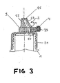
- the first dispensing device shown in Figures 1 to 4 consists of a (attached to the neck 1 of the bottle state the dispenser) fixed spout part 2, a plugged through the spout part 2 and relative to the spout part 2 movable slide 3, and one on one end of the Slider 3 patch cap 4.
- the spout part 2 comprises a fixing portion 21 for Attaching the spout part 2 at the neck 1, and one in the considered Example of dispensing the bottle contained in the bottle Liquid serving spout 22.
- the shape and size the spout 22 are chosen so that a person the spout stuck in the mouth and can drink from it; in the considered Example, the spout 22 is frusto-conical. It It should be noted at this point that the spout 22 may also have any other shape; the Size and shape of the spout are preferably of the intended use made the dispenser dependent.
- the dispenser is opened in the one shown in FIG State of one of three channel parts 23, 24 and 31 existing channel through which the inside of the bottle provided with a at the upper end of the spout 22 Outlet opening 25 connects; via this channel enters the open state of the dispenser shown in Figure 3 the liquid contained in the bottle for Outlet opening 25.
- the traversed by the channel portion 24 section 26 of the spout part 22 has the peculiarity that it is so thin that he by in the normal use of the bottle in this resulting overpressure elastic upward against the slide 3 is pressed.
- the slider 3 serves as a closure device. Leave through him the dispenser from the closed state in the bring open state and vice versa.
- the slider 3 is an elongated element with an oval Cross-section, and is in one above the neck 1 transverse to this extending opening of the spout part 2 is inserted and slidable in the longitudinal direction relative to the spout part 2. It should be noted at this point that the Slider 3 and the associated opening in the spout part 2 need not have an oval cross-section. It can too Any other cross-sections can be used. Important is but that the cross sections of slide 3 and associated Opening match that the outside dimensions of the slider 3 correspond as closely as possible to the internal dimensions of the opening, and that the slide 3 against rotation in the opening to be led.
- the slide 3 contains except the channel part 31 yet another Channel 32.
- This, in the following as a pressure equalization channel designated channel 32 begins to the right of the channel portion 31 at the bottom of the slider 3, starting from this up a bit, then bends to the right and runs from then on in the longitudinal direction of the slider 3 to an am right end of the slide 3 provided pressure equalization opening 33.
- the exact course of the pressure equalization channel 32 is of minor importance. Above all, it is important that in the movement of the slider 3, which are performed to the dispenser of that shown in FIG closed state in the open shown in Figure 3 State, before the time when the Channel part 31 reaches the channel part 23 and / or the channel part 24, via the pressure equalization channel 32 a connection between the inside of the bottle and the pressure equalization opening 33 will be produced.
- the pressure equalization port 33 could also be provided elsewhere. it is located but preferably not in the vicinity of the outlet opening 25th
- the inhalation of these gases would be especially if in the bottle is a carbonated drink, not unproblematic.
- the gas that escapes in this case is namely Carbon dioxide, and its inhalation might be in the person who wants to drink from the bottle, a lack of oxygen and cause the associated side effects.
- Via the pressure compensation opening 33 can also be a ventilation, i.e. a compensation of a prevailing in the bottle vacuum respectively.
- a negative pressure can be in the bottle, for example arise when the bottle is in the Cooling liquid with the dispenser closed, and / or when the bottle is at low air pressure (e.g. on a mountain) and at high air pressure (for example in the valley) should be opened again. Also, aeration of the bottle has the consequence that the Move slider easier.
- the pressure equalization channel 32 is preferably much narrower as the leading to the outlet opening 25 channel. Thereby is prevented from the pressure equalization opening 33rd Liquid can spurt out.
- Dispensing device overlap neither the channel portion 31 of the Slider 3 nor the pressure equalization channel 32 of the slider with the channel part 24.
- liquid leak still on the pressure equalization opening 33 escaping gas.
- It also can not be a liquid and no gas between the slider 3 and the spout part 2 exit.
- the cross sections of the slider 3 and this receiving opening are identical, so that between the Slide 3 and the spout part 2 no spaces available are over which liquid or gas could escape.
- the tightness is also given when within the Bottle, whether by a change in temperature, or by an air pressure change, or by a carbonated Drink, or by any other circumstance forms an overpressure.
- cap 4 is on the right end placed on the slide and beats in the in the figure 1 shown closed state of the dispenser on the spout part 2 on. On this cap 4 can be omitted if the end of the slide 3, on which in the example considered the cap 4 is placed, a corresponding, as Stop has usable thickening.
- the pressure equalization channel 32 is still completely or partially open, if with the Preparation of the connection between the bottle interior and the outlet opening 25 is started, and only more or closed less long afterwards.
- the Pressure equalization channel 32 and / or the pressure compensation opening 33 is very small, more precisely such a small cross-section or is so small that there is no or only negligible little liquid could escape
- the pressure equalization channel 33 with existing connection between the Bottle inside and the outlet opening 25 also still fully or partially open; then could about the pressure equalization opening 33 even while drinking a pressure equalization done, which makes drinking not or less often should be interrupted to the resulting from drinking To compensate for overpressure or negative pressure.
- the described dispenser still has beyond two more special features.
- the second of the special features mentioned is that the channel leading to the outlet opening 25 not straight after runs up, but has an oblique course. Thereby can be achieved that the dispenser despite their asymmetrical structure a lying in the middle Focus. This proves to be beneficial because the dispenser by shaking it quickly into one Position can be brought, in which they detected by a gripper and can be placed on the bottleneck.
- FIG. 5 Another dispenser, which this and the next The advantages mentioned above are also shown in FIG. 5 shown.
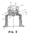
- the second dispensing device shown in Figure 5 consists from a (attached to the neck 1 state of the dispenser) fixed support part 5, one with the support part Connectable Spout Part 6, one at the Spout Part 6 fixed pin 7, and one held by the pin 7 Sealing washer 8.
- the carrier part 5 has the shape of a stepped hollow cylinder with a large diameter lower part 51, and a smaller diameter Top 52. At the bottom 51 an internal thread is provided, through which the carrier part 5 on the neck 1 of the bottle can be screwed on. On the upper part 52, an external thread is provided, on which the spout part 6 can be screwed. Approximately where the lower part 51 and the upper part 52 meet, a pressure compensation opening 53 is provided, about which, as will be described in more detail later, a in the bottle prevailing overpressure or reduced pressure can be.
- the spout part 6 consists of a substantially cup-shaped Body 61 with an outgoing from the top, and first to the outside and then substantially parallel to Body 61 downwardly extending edge 62nd
- the edge 62 has an internal thread, which on the External thread of the upper part 52 of the support member 5 screwed is.
- the body 61 is open at the top; its upper end forms a spout 63 for dispensing the bottle contained in the bottle Liquid.
- the shape and size of the spout 63 are chosen in the example considered so that a person the spout 63 into the mouth and drink from it.
- the spout 63 can in principle be any shape and any Have size; the shape and size of the spout 63 are preferably the intended use of the dispenser made dependent.
- the body 61 is closed at the bottom by a bottom 64.
- a bottom 64 Preferably in the middle of the bottom 64 is a Opening provided through which the pin 7 can be pushed through is.
- the body 61 has in the lower area a this about his full circumference circumferential and provided with openings 66 Indentation 65 on
- the sealing disk 8 is a circular in the example considered trained disc, in the closed state the dispenser from below against the upper part 52 of the Carrier part 5 is pressed and the bottle liquid- and gas-tight closes.
- the pin 7 has different along its length Diameter up.
- the smallest diameter, i. the upper Part of the pin 7 has from above one or more in Longitudinal direction of the pin 7 extending slots.
- the separated by the at least one slot Pin parts are elastically movable and point to their free Ends outwardly projecting latching hooks, which in by the Opening the bottom 64 of the body 61 inserted state of the pin 7 engage behind the opening and thereby a Pulling out the pin 7 from the bottom 64 of the body 61st prevent opening provided.
- the sealing disc 8 is fixed to the body 61.
- the pin 7 is for this purpose from below through the sealing washer 8 inserted, and then - also from below - passed through the bottom 64 of the body 61.
- the opening and closing of the dispenser is done by Turning the spout part 6, more precisely by a different wide screwing the spout part 6 on the Carrier part 5. As a result, the spout part 6 moves relatively to the carrier part 5 up or down.
- the dispenser is closed when the spout part 6 is only slightly screwed onto the carrier part 5, and is opened when the spout part 6 far on the support part. 5 is screwed on.
- the spout part 6 Upon further screwing the spout part 6 on the carrier part 5, the spout part 6 continues to move down. There Finally, the bottom 64 of the spout part 6 passes between the lower part 51 and the upper part 52 of the carrier part. 5 existing stage. When this is done, it can be out of the bottle interior Liquid into the indentation 65, and from there continue on the provided in the indentation 65 breakthroughs 66 reach the spout 63. The dispenser is from there open.
- the bottle Before the bottom 64 of the spout part 6 between the lower part 51 and the upper part 52 of the carrier part 5 existing Stage has passed, the bottle can not be taken out of liquid be because here the inside of the upper part 52 of the carrier part 5 along sliding floor 64 of the liquid the way blocked to the indentation 65.
- the spout part 6 Upon further screwing the spout part 6 on the carrier part 5, the spout part 6 continues to move down until he is finally completely open.
- the external thread on the upper part 52 of the carrier part 5 and the Internal threads on the edge 62 of the spout part 6 preferably have a very large slope, so that the spout part. 6 already by the fraction of a turn from the closed Position in the open position can be brought.
- a great advantage of that described with reference to FIG Dispensing device is that the spout part 6, which at the same time the closure device of the dispensing device forms, by their operation, the dispenser from the opened (fluid-dispensing) state into closed (no liquid dispensing) state and vice versa is bringable, bringing the dispenser in the open state must be moved to the bottle.
- This is different from many known dispensers excluded in all circumstances, that the dispenser by a pressure prevailing in the bottle is brought into the open state.
- Another big advantage of referring to the figure 5 described dispenser is the presence the pressure equalization opening 53. This allows the Bring the dispenser in the open position with low Force is possible. Through the pressure equalization opening 53 can also be prevented when bringing the Dispensing device in the open position liquid from the Spout 63 squirts, and that the drinker or carbonated other harmful gases can or must breathe.
- the Pressure equalization opening 53 in the open state of the dispenser not closed is advantageous.
- the dispensing device shown in Figure 5 easily possible to make sure that the pressure equalization opening 53 is completely or partially closed, if from the Dispensing device fluid can be removed.
- the spout part 6 at the points in the open state of the dispenser on the Pressure equalization opening 53 are located, no indentation 65 with Breakthroughs 66 has. Then the pressure equalization opening 53 in the open state of the dispenser by the buckle-free body 61 closed.
- An unmentioned further advantage of the described Dispensers is that the pressure equalization very simple way was realized. Especially the pressure equalization and the delivery of the in the bottle take place contained liquid via one and the same opening of the Bottle. This allows the described dispensing devices in any conventional bottles and other containers be used.
Landscapes
- Engineering & Computer Science (AREA)
- Mechanical Engineering (AREA)
- Closures For Containers (AREA)
- Containers And Packaging Bodies Having A Special Means To Remove Contents (AREA)
- Exposure And Positioning Against Photoresist Photosensitive Materials (AREA)
- Basic Packing Technique (AREA)
- Lubricants (AREA)
- Devices For Dispensing Beverages (AREA)
- Packages (AREA)
- Filling Of Jars Or Cans And Processes For Cleaning And Sealing Jars (AREA)
- Nozzles (AREA)
Claims (8)
- Dispositif de distribution obturable pour distribuer un milieu liquide, visqueux ou pâteux contenu dans un récipient, comprenant une première ouverture (25 ; 63) pour distribuer le milieu se trouvant dans le récipient, une deuxième ouverture (33 ; 53) d'aérage et/ou de désaérage du récipient, et un dispositif de fermeture (3 ; 6), dont l'actionnement permet de créer et de supprimer une connexion entre la première ouverture (25 ; 63) et le récipient et entre la deuxième ouverture (33 ; 53) et le récipient, le dispositif de fermeture (3 ; 6) étant réalisé de telle sorte que, lors de l'actionnement qui doit être réalisé pour créer une connexion entre la première ouverture (25 ; 63) et le récipient, il crée d'abord une connexion entre la deuxième ouverture (33 ; 53) et le récipient et crée seulement ensuite la connexion entre la première ouverture (25 ; 63) et le récipient, caractérisé en ce que le dispositif de distribution est réalisé de telle sorte qu'il n'existe aucune connexion entre la deuxième ouverture (33 ; 53) et le récipient, lorsqu'il existe une connexion entre la première ouverture (25 ; 63) et le récipient.
- Dispositif de distribution selon la revendication 1, caractérisé en ce que le récipient est une bouteille de boisson.
- Dispositif de distribution selon la revendication 1 ou 2, caractérisé en ce que la deuxième ouverture (33 ; 53) est disposée de telle sorte qu'une personne qui ouvre le dispositif de distribution avec la bouche, ou qui place la première ouverture (25 ; 63) en bouche déjà pendant l'ouverture du dispositif de distribution, ne puisse ou ne doive pas inspirer les gaz sortant de la deuxième ouverture (33 ; 53) au cours du désaérage du récipient.
- Dispositif de distribution selon l'une quelconque des revendications précédentes, caractérisé en ce que le dispositif de fermeture (3 ; 6) est formé par un coulisseau (3) pouvant être coulissé transversalement à la connexion entre la première ouverture (25 ; 63) et le récipient.
- Dispositif de distribution selon la revendication 4, caractérisé en ce que la partie (26) du dispositif de distribution qui est disposée entre le récipient et le coulisseau est au moins en partie une pièce pouvant être pressée élastiquement contre le coulisseau (3) par une surpression existant dans le récipient.
- Dispositif de distribution selon l'une quelconque des revendications précédentes, caractérisé en ce que le dispositif de fermeture (3 ; 6) est formé par un élément (6) déplaçable le long de la connexion entre la première ouverture (25 ; 63) et le récipient.
- Dispositif de distribution selon la revendication 6, caractérisé en ce que le déplacement du dispositif de fermeture (3 ; 6) s'effectue par un vissage du dispositif de fermeture sur un autre composant (5) du dispositif de distribution ou par un dévissage du dispositif de fermeture.
- Dispositif de distribution selon la revendication 6 ou 7, caractérisé en ce que le dispositif de fermeture (3 ; 6) se trouve dans une première position lorsque le dispositif de distribution est fermé et en ce que le dispositif de fermeture (3 ; 6) se trouve dans une deuxième position lorsque le dispositif de distribution est ouvert, la première position étant plus éloignée du récipient que la deuxième position.
Applications Claiming Priority (3)
| Application Number | Priority Date | Filing Date | Title |
|---|---|---|---|
| DE10113109A DE10113109A1 (de) | 2001-03-15 | 2001-03-15 | Verschließbare Abgabevorrichtung zur Abgabe eines in einem Behälter enthaltenen flüssigen, viskosen oder pastösen Mediums |
| DE10113109 | 2001-03-15 | ||
| PCT/DE2002/000058 WO2002074651A2 (fr) | 2001-03-15 | 2002-01-10 | Dispositif de degagement fermable destine a la distribution d'un milieu liquide, visqueux ou pateux contenu dans un recipient |
Publications (2)
| Publication Number | Publication Date |
|---|---|
| EP1368246A2 EP1368246A2 (fr) | 2003-12-10 |
| EP1368246B1 true EP1368246B1 (fr) | 2005-08-10 |
Family
ID=7677979
Family Applications (1)
| Application Number | Title | Priority Date | Filing Date |
|---|---|---|---|
| EP02704569A Expired - Lifetime EP1368246B1 (fr) | 2001-03-15 | 2002-01-10 | Dispositif de degagement fermable destine a la distribution d'un milieu liquide, visqueux ou pateux contenu dans un recipient |
Country Status (19)
| Country | Link |
|---|---|
| US (1) | US6896161B2 (fr) |
| EP (1) | EP1368246B1 (fr) |
| JP (1) | JP2004525828A (fr) |
| KR (1) | KR20030094282A (fr) |
| CN (1) | CN1262450C (fr) |
| AT (1) | ATE301588T1 (fr) |
| AU (1) | AU2002238374B2 (fr) |
| BR (1) | BR0208057A (fr) |
| CA (1) | CA2439466A1 (fr) |
| DE (3) | DE10113109A1 (fr) |
| ES (1) | ES2247300T3 (fr) |
| HU (1) | HUP0303522A3 (fr) |
| MA (1) | MA26087A1 (fr) |
| MX (1) | MXPA03008299A (fr) |
| PL (1) | PL363389A1 (fr) |
| RU (1) | RU2279383C2 (fr) |
| TN (1) | TNSN03070A1 (fr) |
| WO (1) | WO2002074651A2 (fr) |
| ZA (1) | ZA200307144B (fr) |
Families Citing this family (19)
| Publication number | Priority date | Publication date | Assignee | Title |
|---|---|---|---|---|
| AU2003206617A1 (en) * | 2002-01-10 | 2003-07-24 | Bmf Gmbh | Sealable dispenser device for dispensing a fluid, viscous or pasty medium contained in a container |
| CA2522134A1 (fr) * | 2003-05-14 | 2004-11-25 | Lasse Kjeldsen | Bec verseur pour recipient contenant un liquide, recipient et procede d'utilisation |
| DE102004029488B3 (de) * | 2004-06-18 | 2006-01-19 | Henkel Kgaa | Verschluss für einen Behälter |
| US20060134354A1 (en) * | 2004-12-16 | 2006-06-22 | Walters Jay M | Calibration vial stopper with improved security features |
| DE102005029746B4 (de) | 2005-06-24 | 2017-10-26 | Boehringer Ingelheim International Gmbh | Zerstäuber |
| WO2011031639A1 (fr) * | 2009-09-08 | 2011-03-17 | Calibre Closures Llc | Bouchon distributeur refermable amélioré |
| EP2369311B1 (fr) * | 2010-03-15 | 2015-04-15 | Mettler-Toledo AG | Unité de dosage pour substances pouvant s'écouler |
| US8863997B2 (en) * | 2010-06-18 | 2014-10-21 | Steven Hickey | Fuel delivery nozzle and air vent and portable container having same |
| US8459502B2 (en) * | 2010-09-03 | 2013-06-11 | Calibre Closures, LLC | Reclosable dispensing closure with vent |
| WO2013171351A1 (fr) * | 2012-05-18 | 2013-11-21 | Desarrollos Tamarit Plaza Sl | Couvercle avec bouchon pour récipient de boissons |
| CN102582928B (zh) * | 2012-02-17 | 2015-03-11 | 莫尼托有限公司 | 一种可快速打开的瓶盖 |
| US9205020B2 (en) * | 2012-04-27 | 2015-12-08 | Young Living Essential Oils, Lc | Massaging multiple roller-ball applicator for topical oils application |
| US9211228B2 (en) * | 2012-04-27 | 2015-12-15 | Young Living Essential Oils, Lc | Massaging topical oils applicator |
| ITMO20130134A1 (it) * | 2013-05-16 | 2014-11-17 | Piazza Effepi S R L | Tappo versatore perfezionato. |
| US9259110B2 (en) * | 2013-10-08 | 2016-02-16 | Louis Garneau Sports Inc. | Sport bottle with closing mechanism |
| US10301057B2 (en) | 2016-07-11 | 2019-05-28 | Calibre Closures Llc | Dispensing container with internal squeeze limiting member |
| US9783348B1 (en) * | 2017-03-24 | 2017-10-10 | Trong D Nguyen | Personal dispensing systems |
| CN108379711B (zh) * | 2018-04-28 | 2024-05-14 | 佘小斌 | 水流控制装置、冷凝水收集杯及呼吸机 |
| US11185148B2 (en) * | 2020-03-06 | 2021-11-30 | Custom Club, Inc. | Oral device container and oral device container and bottle assembly |
Family Cites Families (20)
| Publication number | Priority date | Publication date | Assignee | Title |
|---|---|---|---|---|
| DE183301C (fr) * | ||||
| US732620A (en) * | 1902-08-13 | 1903-06-30 | Joseph A Dinkler | Druggist's dispensing oil-can. |
| GB646114A (en) * | 1948-07-19 | 1950-11-15 | Karl Grienseyss | Improvements in closures for receptacles adapted to discharge the contents in drops,streams or otherwise |
| US2971680A (en) * | 1957-05-27 | 1961-02-14 | Woodrow S Wilson | Dispensing caps |
| US2979238A (en) * | 1959-04-15 | 1961-04-11 | Aladdin Ind Inc | Sip-through and pour-through closure for vacuum bottles or the like |
| US3146913A (en) * | 1961-06-29 | 1964-09-01 | Nagai Kiyoshi | Cap having a non-drip spout |
| DE1202157B (de) * | 1961-08-24 | 1965-09-30 | Kiyoshi Nagai | Ausgiessvorrichtung fuer Fluessigkeitsbehaelter mit einem Schieberhuelsenventil |
| US3757981A (en) * | 1969-11-24 | 1973-09-11 | Harris R | Valves and valve needle syringes |
| US3731855A (en) * | 1971-06-30 | 1973-05-08 | Johnson & Son Inc S C | Pressurized containers |
| US4057167A (en) * | 1976-12-01 | 1977-11-08 | Jin Ku Lee | Valved receptacle closure |
| FR2627156B1 (fr) * | 1988-02-12 | 1990-08-24 | Simon Patrick | Capsule de fermeture a element mobile pour flacons et autres recipients |
| US5065909A (en) * | 1989-11-29 | 1991-11-19 | Threeco | Vented beverage can cover having pivotal spout |
| CH681075A5 (fr) * | 1990-06-08 | 1993-01-15 | Sigg Aluminium & Metallwaren | |
| US5289945A (en) * | 1992-02-27 | 1994-03-01 | Stradder Robert H | Sealing and dispensing cap |
| GB2283012A (en) * | 1993-10-20 | 1995-04-26 | Chen Maokuei | Cap and tube apparatus. |
| US5620114A (en) * | 1996-01-31 | 1997-04-15 | Chalfa, Jr.; Bobby L. | Sliding valve for single handed fluid dispensing |
| EP0826607A1 (fr) * | 1996-08-23 | 1998-03-04 | W.L. GORE & ASSOCIATES GmbH | Fermeture pour bidon |
| WO2001002264A1 (fr) * | 1999-06-30 | 2001-01-11 | Joma Kunststoffwerk Und Warenhandel Gesellschaft M.B.H. | Dispositif de fermeture d'un recipient |
| DE19937754A1 (de) | 1999-08-10 | 2001-02-15 | Fischer Uwe | Trinkflaschenverschluß |
| US6213351B1 (en) * | 1999-12-27 | 2001-04-10 | Courtesy Corporation | Push body valve closure |
-
2001
- 2001-03-15 DE DE10113109A patent/DE10113109A1/de not_active Withdrawn
-
2002
- 2002-01-10 JP JP2002573326A patent/JP2004525828A/ja active Pending
- 2002-01-10 EP EP02704569A patent/EP1368246B1/fr not_active Expired - Lifetime
- 2002-01-10 DE DE10291061T patent/DE10291061D2/de not_active Expired - Fee Related
- 2002-01-10 KR KR10-2003-7012002A patent/KR20030094282A/ko not_active Ceased
- 2002-01-10 PL PL02363389A patent/PL363389A1/xx unknown
- 2002-01-10 AU AU2002238374A patent/AU2002238374B2/en not_active Ceased
- 2002-01-10 DE DE50203883T patent/DE50203883D1/de not_active Expired - Lifetime
- 2002-01-10 BR BR0208057-5A patent/BR0208057A/pt not_active IP Right Cessation
- 2002-01-10 RU RU2003130371/12A patent/RU2279383C2/ru active
- 2002-01-10 ES ES02704569T patent/ES2247300T3/es not_active Expired - Lifetime
- 2002-01-10 AT AT02704569T patent/ATE301588T1/de not_active IP Right Cessation
- 2002-01-10 CA CA002439466A patent/CA2439466A1/fr not_active Abandoned
- 2002-01-10 WO PCT/DE2002/000058 patent/WO2002074651A2/fr not_active Ceased
- 2002-01-10 HU HU0303522A patent/HUP0303522A3/hu unknown
- 2002-01-10 MX MXPA03008299A patent/MXPA03008299A/es active IP Right Grant
- 2002-01-10 CN CNB02806609XA patent/CN1262450C/zh not_active Expired - Fee Related
-
2003
- 2003-07-08 TN TNPCT/DE2002/000058A patent/TNSN03070A1/en unknown
- 2003-08-25 MA MA27289A patent/MA26087A1/fr unknown
- 2003-09-12 ZA ZA200307144A patent/ZA200307144B/en unknown
- 2003-09-15 US US10/662,631 patent/US6896161B2/en not_active Expired - Fee Related
Also Published As
| Publication number | Publication date |
|---|---|
| BR0208057A (pt) | 2004-03-02 |
| CN1262450C (zh) | 2006-07-05 |
| MXPA03008299A (es) | 2003-12-11 |
| EP1368246A2 (fr) | 2003-12-10 |
| MA26087A1 (fr) | 2004-04-01 |
| ATE301588T1 (de) | 2005-08-15 |
| WO2002074651A2 (fr) | 2002-09-26 |
| US6896161B2 (en) | 2005-05-24 |
| DE10113109A1 (de) | 2002-09-19 |
| ES2247300T3 (es) | 2006-03-01 |
| JP2004525828A (ja) | 2004-08-26 |
| CN1527783A (zh) | 2004-09-08 |
| CA2439466A1 (fr) | 2002-09-26 |
| AU2002238374B2 (en) | 2006-11-23 |
| ZA200307144B (en) | 2004-09-06 |
| RU2279383C2 (ru) | 2006-07-10 |
| PL363389A1 (en) | 2004-11-15 |
| HUP0303522A2 (hu) | 2004-03-01 |
| US20040094580A1 (en) | 2004-05-20 |
| HUP0303522A3 (en) | 2005-11-28 |
| DE50203883D1 (de) | 2005-09-15 |
| KR20030094282A (ko) | 2003-12-11 |
| WO2002074651A3 (fr) | 2003-01-23 |
| DE10291061D2 (de) | 2004-04-15 |
| TNSN03070A1 (en) | 2005-04-08 |
Similar Documents
| Publication | Publication Date | Title |
|---|---|---|
| EP1368246B1 (fr) | Dispositif de degagement fermable destine a la distribution d'un milieu liquide, visqueux ou pateux contenu dans un recipient | |
| DE60031392T2 (de) | Behälterverschluss | |
| EP0089064B2 (fr) | Dispositif pour transvaser des liquides, spécialement des moyens liquides pour permanentes | |
| DE2934711A1 (de) | Wiederverschliessbarer fluessigkeits- behaelter | |
| DE1916093C3 (de) | Ventil zum Ausgeben eines Mate nalgemisches aus mehreren Behaltern | |
| DE3302842A1 (de) | Behaeltnis, insbesondere trinkgefaess | |
| EP0963944A1 (fr) | Récipient pour boisson comme boíte, tonnelet ou fût | |
| DE69714785T2 (de) | Verschlusskappe mit garantieband | |
| EP0716638B1 (fr) | Bouchon de fermeture | |
| CH681075A5 (fr) | ||
| DE3302869A1 (de) | Behaelterverschluss | |
| DE102005022446B3 (de) | Partyfass | |
| DE9303734U1 (de) | Trinkverschluß für eine Trinkflasche | |
| DE3004119A1 (de) | Entnahmehahn | |
| DE602004008062T2 (de) | Ausguss für flüssigkeitsbehälter sowie behälter, verfahren und verwendung dafür | |
| CH691262A5 (de) | Kunststoffhahnen für Flüssigkeitsbehälter. | |
| DE10200748A1 (de) | Verschließbare Abgabevorrichtung zur Abgabe eines in einem Behälter enthaltenen flüssigen, viskosen oder pastösen Mediums | |
| DE4219571C2 (de) | Vorrichtung zur Entnahme einer Flüssigkeit aus einem Behälter, insbesondere aus einer 10- bzw. 5-Liter Faßdose für Bier | |
| AT405736B (de) | Ausgiesser für flaschen | |
| DE2524624C3 (de) | Flüssigkeitsspender, insbesondere für flüssige Seife | |
| EP1463671A1 (fr) | Dispositif de distribution pouvant fermer et destine a la distribution d'un agent liquide, visqueux ou pateux contenu dans un contenant | |
| CH716564A1 (de) | Behälterverschluss zum Befestigen an einer Mündung eines Behälters und Behälter mit einem solchen Behälterverschluss. | |
| AT413095B (de) | Behälter | |
| DE20116142U1 (de) | Verschluss für eine Getränkeflasche und Getränkeflasche mit Verschluss | |
| DE4332087A1 (de) | Verschluß- und Entnahmeeinrichtung |
Legal Events
| Date | Code | Title | Description |
|---|---|---|---|
| PUAI | Public reference made under article 153(3) epc to a published international application that has entered the european phase |
Free format text: ORIGINAL CODE: 0009012 |
|
| 17P | Request for examination filed |
Effective date: 20030901 |
|
| AK | Designated contracting states |
Kind code of ref document: A2 Designated state(s): AT BE CH CY DE DK ES FI FR GB GR IE IT LI LU MC NL PT SE TR |
|
| AX | Request for extension of the european patent |
Extension state: AL LT LV MK RO SI |
|
| 17Q | First examination report despatched |
Effective date: 20040212 |
|
| GRAP | Despatch of communication of intention to grant a patent |
Free format text: ORIGINAL CODE: EPIDOSNIGR1 |
|
| GRAS | Grant fee paid |
Free format text: ORIGINAL CODE: EPIDOSNIGR3 |
|
| GRAA | (expected) grant |
Free format text: ORIGINAL CODE: 0009210 |
|
| AK | Designated contracting states |
Kind code of ref document: B1 Designated state(s): AT BE CH CY DE DK ES FI FR GB GR IE IT LI LU MC NL PT SE TR |
|
| AX | Request for extension of the european patent |
Extension state: RO |
|
| PG25 | Lapsed in a contracting state [announced via postgrant information from national office to epo] |
Ref country code: IE Free format text: LAPSE BECAUSE OF FAILURE TO SUBMIT A TRANSLATION OF THE DESCRIPTION OR TO PAY THE FEE WITHIN THE PRESCRIBED TIME-LIMIT Effective date: 20050810 Ref country code: FI Free format text: LAPSE BECAUSE OF FAILURE TO SUBMIT A TRANSLATION OF THE DESCRIPTION OR TO PAY THE FEE WITHIN THE PRESCRIBED TIME-LIMIT Effective date: 20050810 |
|
| REG | Reference to a national code |
Ref country code: GB Ref legal event code: FG4D Free format text: NOT ENGLISH |
|
| REG | Reference to a national code |
Ref country code: CH Ref legal event code: EP |
|
| REG | Reference to a national code |
Ref country code: IE Ref legal event code: FG4D Free format text: LANGUAGE OF EP DOCUMENT: GERMAN |
|
| REF | Corresponds to: |
Ref document number: 50203883 Country of ref document: DE Date of ref document: 20050915 Kind code of ref document: P |
|
| PG25 | Lapsed in a contracting state [announced via postgrant information from national office to epo] |
Ref country code: GR Free format text: LAPSE BECAUSE OF FAILURE TO SUBMIT A TRANSLATION OF THE DESCRIPTION OR TO PAY THE FEE WITHIN THE PRESCRIBED TIME-LIMIT Effective date: 20051110 Ref country code: DK Free format text: LAPSE BECAUSE OF FAILURE TO SUBMIT A TRANSLATION OF THE DESCRIPTION OR TO PAY THE FEE WITHIN THE PRESCRIBED TIME-LIMIT Effective date: 20051110 |
|
| REG | Reference to a national code |
Ref country code: SE Ref legal event code: TRGR |
|
| GBT | Gb: translation of ep patent filed (gb section 77(6)(a)/1977) |
Effective date: 20051109 |
|
| REG | Reference to a national code |
Ref country code: CH Ref legal event code: NV Representative=s name: KELLER & PARTNER PATENTANWAELTE AG |
|
| PG25 | Lapsed in a contracting state [announced via postgrant information from national office to epo] |
Ref country code: PT Free format text: LAPSE BECAUSE OF FAILURE TO SUBMIT A TRANSLATION OF THE DESCRIPTION OR TO PAY THE FEE WITHIN THE PRESCRIBED TIME-LIMIT Effective date: 20060110 |
|
| PG25 | Lapsed in a contracting state [announced via postgrant information from national office to epo] |
Ref country code: LU Free format text: LAPSE BECAUSE OF NON-PAYMENT OF DUE FEES Effective date: 20060131 Ref country code: BE Free format text: LAPSE BECAUSE OF NON-PAYMENT OF DUE FEES Effective date: 20060131 Ref country code: MC Free format text: LAPSE BECAUSE OF NON-PAYMENT OF DUE FEES Effective date: 20060131 |
|
| REG | Reference to a national code |
Ref country code: ES Ref legal event code: FG2A Ref document number: 2247300 Country of ref document: ES Kind code of ref document: T3 |
|
| REG | Reference to a national code |
Ref country code: IE Ref legal event code: FD4D |
|
| ET | Fr: translation filed | ||
| PLBE | No opposition filed within time limit |
Free format text: ORIGINAL CODE: 0009261 |
|
| STAA | Information on the status of an ep patent application or granted ep patent |
Free format text: STATUS: NO OPPOSITION FILED WITHIN TIME LIMIT |
|
| 26N | No opposition filed |
Effective date: 20060511 |
|
| BERE | Be: lapsed |
Owner name: BMF G.M.B.H. Effective date: 20060131 |
|
| PG25 | Lapsed in a contracting state [announced via postgrant information from national office to epo] |
Ref country code: CY Free format text: LAPSE BECAUSE OF FAILURE TO SUBMIT A TRANSLATION OF THE DESCRIPTION OR TO PAY THE FEE WITHIN THE PRESCRIBED TIME-LIMIT Effective date: 20050810 |
|
| PGFP | Annual fee paid to national office [announced via postgrant information from national office to epo] |
Ref country code: AT Payment date: 20090114 Year of fee payment: 8 Ref country code: ES Payment date: 20090119 Year of fee payment: 8 |
|
| PGFP | Annual fee paid to national office [announced via postgrant information from national office to epo] |
Ref country code: NL Payment date: 20090119 Year of fee payment: 8 |
|
| PGFP | Annual fee paid to national office [announced via postgrant information from national office to epo] |
Ref country code: CH Payment date: 20090119 Year of fee payment: 8 Ref country code: GB Payment date: 20090112 Year of fee payment: 8 |
|
| PGFP | Annual fee paid to national office [announced via postgrant information from national office to epo] |
Ref country code: IT Payment date: 20090122 Year of fee payment: 8 Ref country code: SE Payment date: 20090115 Year of fee payment: 8 Ref country code: TR Payment date: 20090108 Year of fee payment: 8 |
|
| PGFP | Annual fee paid to national office [announced via postgrant information from national office to epo] |
Ref country code: FR Payment date: 20090128 Year of fee payment: 8 |
|
| REG | Reference to a national code |
Ref country code: NL Ref legal event code: V1 Effective date: 20100801 |
|
| REG | Reference to a national code |
Ref country code: CH Ref legal event code: PL |
|
| GBPC | Gb: european patent ceased through non-payment of renewal fee |
Effective date: 20100110 |
|
| EUG | Se: european patent has lapsed | ||
| REG | Reference to a national code |
Ref country code: FR Ref legal event code: ST Effective date: 20100930 |
|
| PG25 | Lapsed in a contracting state [announced via postgrant information from national office to epo] |
Ref country code: CH Free format text: LAPSE BECAUSE OF NON-PAYMENT OF DUE FEES Effective date: 20100131 Ref country code: FR Free format text: LAPSE BECAUSE OF NON-PAYMENT OF DUE FEES Effective date: 20100201 Ref country code: LI Free format text: LAPSE BECAUSE OF NON-PAYMENT OF DUE FEES Effective date: 20100131 Ref country code: NL Free format text: LAPSE BECAUSE OF NON-PAYMENT OF DUE FEES Effective date: 20100801 |
|
| PG25 | Lapsed in a contracting state [announced via postgrant information from national office to epo] |
Ref country code: AT Free format text: LAPSE BECAUSE OF NON-PAYMENT OF DUE FEES Effective date: 20100110 |
|
| PG25 | Lapsed in a contracting state [announced via postgrant information from national office to epo] |
Ref country code: GB Free format text: LAPSE BECAUSE OF NON-PAYMENT OF DUE FEES Effective date: 20100110 |
|
| PG25 | Lapsed in a contracting state [announced via postgrant information from national office to epo] |
Ref country code: IT Free format text: LAPSE BECAUSE OF NON-PAYMENT OF DUE FEES Effective date: 20100110 |
|
| REG | Reference to a national code |
Ref country code: ES Ref legal event code: FD2A Effective date: 20110404 |
|
| PG25 | Lapsed in a contracting state [announced via postgrant information from national office to epo] |
Ref country code: ES Free format text: LAPSE BECAUSE OF NON-PAYMENT OF DUE FEES Effective date: 20110322 |
|
| PG25 | Lapsed in a contracting state [announced via postgrant information from national office to epo] |
Ref country code: ES Free format text: LAPSE BECAUSE OF NON-PAYMENT OF DUE FEES Effective date: 20100111 |
|
| PG25 | Lapsed in a contracting state [announced via postgrant information from national office to epo] |
Ref country code: SE Free format text: LAPSE BECAUSE OF NON-PAYMENT OF DUE FEES Effective date: 20100111 |
|
| PG25 | Lapsed in a contracting state [announced via postgrant information from national office to epo] |
Ref country code: TR Free format text: LAPSE BECAUSE OF NON-PAYMENT OF DUE FEES Effective date: 20100110 |
|
| PGFP | Annual fee paid to national office [announced via postgrant information from national office to epo] |
Ref country code: DE Payment date: 20130125 Year of fee payment: 12 |
|
| REG | Reference to a national code |
Ref country code: DE Ref legal event code: R119 Ref document number: 50203883 Country of ref document: DE |
|
| REG | Reference to a national code |
Ref country code: DE Ref legal event code: R119 Ref document number: 50203883 Country of ref document: DE Effective date: 20140801 |
|
| PG25 | Lapsed in a contracting state [announced via postgrant information from national office to epo] |
Ref country code: DE Free format text: LAPSE BECAUSE OF NON-PAYMENT OF DUE FEES Effective date: 20140801 |