EP1369285B1 - Procédé et dispositif de démarrage d'un moteur thermique dans un véhicule hybride série - Google Patents
Procédé et dispositif de démarrage d'un moteur thermique dans un véhicule hybride série Download PDFInfo
- Publication number
- EP1369285B1 EP1369285B1 EP03354051A EP03354051A EP1369285B1 EP 1369285 B1 EP1369285 B1 EP 1369285B1 EP 03354051 A EP03354051 A EP 03354051A EP 03354051 A EP03354051 A EP 03354051A EP 1369285 B1 EP1369285 B1 EP 1369285B1
- Authority
- EP
- European Patent Office
- Prior art keywords
- threshold
- temperature
- starter
- electric machine
- heat engine
- Prior art date
- Legal status (The legal status is an assumption and is not a legal conclusion. Google has not performed a legal analysis and makes no representation as to the accuracy of the status listed.)
- Expired - Lifetime
Links
Images
Classifications
-
- B—PERFORMING OPERATIONS; TRANSPORTING
- B60—VEHICLES IN GENERAL
- B60W—CONJOINT CONTROL OF VEHICLE SUB-UNITS OF DIFFERENT TYPE OR DIFFERENT FUNCTION; CONTROL SYSTEMS SPECIALLY ADAPTED FOR HYBRID VEHICLES; ROAD VEHICLE DRIVE CONTROL SYSTEMS FOR PURPOSES NOT RELATED TO THE CONTROL OF A PARTICULAR SUB-UNIT
- B60W20/00—Control systems specially adapted for hybrid vehicles
- B60W20/10—Controlling the power contribution of each of the prime movers to meet required power demand
-
- B—PERFORMING OPERATIONS; TRANSPORTING
- B60—VEHICLES IN GENERAL
- B60K—ARRANGEMENT OR MOUNTING OF PROPULSION UNITS OR OF TRANSMISSIONS IN VEHICLES; ARRANGEMENT OR MOUNTING OF PLURAL DIVERSE PRIME-MOVERS IN VEHICLES; AUXILIARY DRIVES FOR VEHICLES; INSTRUMENTATION OR DASHBOARDS FOR VEHICLES; ARRANGEMENTS IN CONNECTION WITH COOLING, AIR INTAKE, GAS EXHAUST OR FUEL SUPPLY OF PROPULSION UNITS IN VEHICLES
- B60K6/00—Arrangement or mounting of plural diverse prime-movers for mutual or common propulsion, e.g. hybrid propulsion systems comprising electric motors and internal combustion engines
- B60K6/20—Arrangement or mounting of plural diverse prime-movers for mutual or common propulsion, e.g. hybrid propulsion systems comprising electric motors and internal combustion engines the prime-movers consisting of electric motors and internal combustion engines, e.g. HEVs
- B60K6/42—Arrangement or mounting of plural diverse prime-movers for mutual or common propulsion, e.g. hybrid propulsion systems comprising electric motors and internal combustion engines the prime-movers consisting of electric motors and internal combustion engines, e.g. HEVs characterised by the architecture of the hybrid electric vehicle
- B60K6/48—Parallel type
-
- B—PERFORMING OPERATIONS; TRANSPORTING
- B60—VEHICLES IN GENERAL
- B60K—ARRANGEMENT OR MOUNTING OF PROPULSION UNITS OR OF TRANSMISSIONS IN VEHICLES; ARRANGEMENT OR MOUNTING OF PLURAL DIVERSE PRIME-MOVERS IN VEHICLES; AUXILIARY DRIVES FOR VEHICLES; INSTRUMENTATION OR DASHBOARDS FOR VEHICLES; ARRANGEMENTS IN CONNECTION WITH COOLING, AIR INTAKE, GAS EXHAUST OR FUEL SUPPLY OF PROPULSION UNITS IN VEHICLES
- B60K6/00—Arrangement or mounting of plural diverse prime-movers for mutual or common propulsion, e.g. hybrid propulsion systems comprising electric motors and internal combustion engines
- B60K6/20—Arrangement or mounting of plural diverse prime-movers for mutual or common propulsion, e.g. hybrid propulsion systems comprising electric motors and internal combustion engines the prime-movers consisting of electric motors and internal combustion engines, e.g. HEVs
- B60K6/42—Arrangement or mounting of plural diverse prime-movers for mutual or common propulsion, e.g. hybrid propulsion systems comprising electric motors and internal combustion engines the prime-movers consisting of electric motors and internal combustion engines, e.g. HEVs characterised by the architecture of the hybrid electric vehicle
- B60K6/48—Parallel type
- B60K6/485—Motor-assist type
-
- B—PERFORMING OPERATIONS; TRANSPORTING
- B60—VEHICLES IN GENERAL
- B60W—CONJOINT CONTROL OF VEHICLE SUB-UNITS OF DIFFERENT TYPE OR DIFFERENT FUNCTION; CONTROL SYSTEMS SPECIALLY ADAPTED FOR HYBRID VEHICLES; ROAD VEHICLE DRIVE CONTROL SYSTEMS FOR PURPOSES NOT RELATED TO THE CONTROL OF A PARTICULAR SUB-UNIT
- B60W10/00—Conjoint control of vehicle sub-units of different type or different function
- B60W10/04—Conjoint control of vehicle sub-units of different type or different function including control of propulsion units
- B60W10/06—Conjoint control of vehicle sub-units of different type or different function including control of propulsion units including control of combustion engines
-
- B—PERFORMING OPERATIONS; TRANSPORTING
- B60—VEHICLES IN GENERAL
- B60W—CONJOINT CONTROL OF VEHICLE SUB-UNITS OF DIFFERENT TYPE OR DIFFERENT FUNCTION; CONTROL SYSTEMS SPECIALLY ADAPTED FOR HYBRID VEHICLES; ROAD VEHICLE DRIVE CONTROL SYSTEMS FOR PURPOSES NOT RELATED TO THE CONTROL OF A PARTICULAR SUB-UNIT
- B60W10/00—Conjoint control of vehicle sub-units of different type or different function
- B60W10/04—Conjoint control of vehicle sub-units of different type or different function including control of propulsion units
- B60W10/08—Conjoint control of vehicle sub-units of different type or different function including control of propulsion units including control of electric propulsion units, e.g. motors or generators
-
- B—PERFORMING OPERATIONS; TRANSPORTING
- B60—VEHICLES IN GENERAL
- B60W—CONJOINT CONTROL OF VEHICLE SUB-UNITS OF DIFFERENT TYPE OR DIFFERENT FUNCTION; CONTROL SYSTEMS SPECIALLY ADAPTED FOR HYBRID VEHICLES; ROAD VEHICLE DRIVE CONTROL SYSTEMS FOR PURPOSES NOT RELATED TO THE CONTROL OF A PARTICULAR SUB-UNIT
- B60W20/00—Control systems specially adapted for hybrid vehicles
-
- B—PERFORMING OPERATIONS; TRANSPORTING
- B60—VEHICLES IN GENERAL
- B60W—CONJOINT CONTROL OF VEHICLE SUB-UNITS OF DIFFERENT TYPE OR DIFFERENT FUNCTION; CONTROL SYSTEMS SPECIALLY ADAPTED FOR HYBRID VEHICLES; ROAD VEHICLE DRIVE CONTROL SYSTEMS FOR PURPOSES NOT RELATED TO THE CONTROL OF A PARTICULAR SUB-UNIT
- B60W30/00—Purposes of road vehicle drive control systems not related to the control of a particular sub-unit, e.g. of systems using conjoint control of vehicle sub-units
- B60W30/18—Propelling the vehicle
- B60W30/192—Mitigating problems related to power-up or power-down of the driveline, e.g. start-up of a cold engine
- B60W30/194—Mitigating problems related to power-up or power-down of the driveline, e.g. start-up of a cold engine related to low temperature conditions, e.g. high viscosity of hydraulic fluid
-
- F—MECHANICAL ENGINEERING; LIGHTING; HEATING; WEAPONS; BLASTING
- F02—COMBUSTION ENGINES; HOT-GAS OR COMBUSTION-PRODUCT ENGINE PLANTS
- F02N—STARTING OF COMBUSTION ENGINES; STARTING AIDS FOR SUCH ENGINES, NOT OTHERWISE PROVIDED FOR
- F02N11/00—Starting of engines by means of electric motors
- F02N11/006—Starting of engines by means of electric motors using a plurality of electric motors
-
- F—MECHANICAL ENGINEERING; LIGHTING; HEATING; WEAPONS; BLASTING
- F02—COMBUSTION ENGINES; HOT-GAS OR COMBUSTION-PRODUCT ENGINE PLANTS
- F02N—STARTING OF COMBUSTION ENGINES; STARTING AIDS FOR SUCH ENGINES, NOT OTHERWISE PROVIDED FOR
- F02N11/00—Starting of engines by means of electric motors
- F02N11/08—Circuits specially adapted for starting of engines
- F02N11/0862—Circuits specially adapted for starting of engines characterised by the electrical power supply means, e.g. battery
- F02N11/0866—Circuits specially adapted for starting of engines characterised by the electrical power supply means, e.g. battery comprising several power sources, e.g. battery and capacitor or two batteries
-
- B—PERFORMING OPERATIONS; TRANSPORTING
- B60—VEHICLES IN GENERAL
- B60K—ARRANGEMENT OR MOUNTING OF PROPULSION UNITS OR OF TRANSMISSIONS IN VEHICLES; ARRANGEMENT OR MOUNTING OF PLURAL DIVERSE PRIME-MOVERS IN VEHICLES; AUXILIARY DRIVES FOR VEHICLES; INSTRUMENTATION OR DASHBOARDS FOR VEHICLES; ARRANGEMENTS IN CONNECTION WITH COOLING, AIR INTAKE, GAS EXHAUST OR FUEL SUPPLY OF PROPULSION UNITS IN VEHICLES
- B60K6/00—Arrangement or mounting of plural diverse prime-movers for mutual or common propulsion, e.g. hybrid propulsion systems comprising electric motors and internal combustion engines
- B60K6/20—Arrangement or mounting of plural diverse prime-movers for mutual or common propulsion, e.g. hybrid propulsion systems comprising electric motors and internal combustion engines the prime-movers consisting of electric motors and internal combustion engines, e.g. HEVs
- B60K6/22—Arrangement or mounting of plural diverse prime-movers for mutual or common propulsion, e.g. hybrid propulsion systems comprising electric motors and internal combustion engines the prime-movers consisting of electric motors and internal combustion engines, e.g. HEVs characterised by apparatus, components or means specially adapted for HEVs
- B60K6/26—Arrangement or mounting of plural diverse prime-movers for mutual or common propulsion, e.g. hybrid propulsion systems comprising electric motors and internal combustion engines the prime-movers consisting of electric motors and internal combustion engines, e.g. HEVs characterised by apparatus, components or means specially adapted for HEVs characterised by the motors or the generators
- B60K2006/268—Electric drive motor starts the engine, i.e. used as starter motor
-
- B—PERFORMING OPERATIONS; TRANSPORTING
- B60—VEHICLES IN GENERAL
- B60L—PROPULSION OF ELECTRICALLY-PROPELLED VEHICLES; SUPPLYING ELECTRIC POWER FOR AUXILIARY EQUIPMENT OF ELECTRICALLY-PROPELLED VEHICLES; ELECTRODYNAMIC BRAKE SYSTEMS FOR VEHICLES IN GENERAL; MAGNETIC SUSPENSION OR LEVITATION FOR VEHICLES; MONITORING OPERATING VARIABLES OF ELECTRICALLY-PROPELLED VEHICLES; ELECTRIC SAFETY DEVICES FOR ELECTRICALLY-PROPELLED VEHICLES
- B60L2240/00—Control parameters of input or output; Target parameters
- B60L2240/40—Drive Train control parameters
- B60L2240/44—Drive Train control parameters related to combustion engines
- B60L2240/445—Temperature
-
- B—PERFORMING OPERATIONS; TRANSPORTING
- B60—VEHICLES IN GENERAL
- B60W—CONJOINT CONTROL OF VEHICLE SUB-UNITS OF DIFFERENT TYPE OR DIFFERENT FUNCTION; CONTROL SYSTEMS SPECIALLY ADAPTED FOR HYBRID VEHICLES; ROAD VEHICLE DRIVE CONTROL SYSTEMS FOR PURPOSES NOT RELATED TO THE CONTROL OF A PARTICULAR SUB-UNIT
- B60W2510/00—Input parameters relating to a particular sub-units
- B60W2510/06—Combustion engines, Gas turbines
- B60W2510/0676—Engine temperature
-
- F—MECHANICAL ENGINEERING; LIGHTING; HEATING; WEAPONS; BLASTING
- F02—COMBUSTION ENGINES; HOT-GAS OR COMBUSTION-PRODUCT ENGINE PLANTS
- F02N—STARTING OF COMBUSTION ENGINES; STARTING AIDS FOR SUCH ENGINES, NOT OTHERWISE PROVIDED FOR
- F02N11/00—Starting of engines by means of electric motors
- F02N11/08—Circuits specially adapted for starting of engines
- F02N11/0814—Circuits specially adapted for starting of engines comprising means for controlling automatic idle-start-stop
-
- F—MECHANICAL ENGINEERING; LIGHTING; HEATING; WEAPONS; BLASTING
- F02—COMBUSTION ENGINES; HOT-GAS OR COMBUSTION-PRODUCT ENGINE PLANTS
- F02N—STARTING OF COMBUSTION ENGINES; STARTING AIDS FOR SUCH ENGINES, NOT OTHERWISE PROVIDED FOR
- F02N19/00—Starting aids for combustion engines, not otherwise provided for
-
- F—MECHANICAL ENGINEERING; LIGHTING; HEATING; WEAPONS; BLASTING
- F02—COMBUSTION ENGINES; HOT-GAS OR COMBUSTION-PRODUCT ENGINE PLANTS
- F02N—STARTING OF COMBUSTION ENGINES; STARTING AIDS FOR SUCH ENGINES, NOT OTHERWISE PROVIDED FOR
- F02N11/00—Starting of engines by means of electric motors
- F02N11/08—Circuits specially adapted for starting of engines
- F02N2011/0881—Components of the circuit not provided for by previous groups
- F02N2011/0888—DC/DC converters
-
- F—MECHANICAL ENGINEERING; LIGHTING; HEATING; WEAPONS; BLASTING
- F02—COMBUSTION ENGINES; HOT-GAS OR COMBUSTION-PRODUCT ENGINE PLANTS
- F02N—STARTING OF COMBUSTION ENGINES; STARTING AIDS FOR SUCH ENGINES, NOT OTHERWISE PROVIDED FOR
- F02N2200/00—Parameters used for control of starting apparatus
- F02N2200/02—Parameters used for control of starting apparatus said parameters being related to the engine
- F02N2200/023—Engine temperature
-
- F—MECHANICAL ENGINEERING; LIGHTING; HEATING; WEAPONS; BLASTING
- F02—COMBUSTION ENGINES; HOT-GAS OR COMBUSTION-PRODUCT ENGINE PLANTS
- F02N—STARTING OF COMBUSTION ENGINES; STARTING AIDS FOR SUCH ENGINES, NOT OTHERWISE PROVIDED FOR
- F02N2300/00—Control related aspects of engine starting
- F02N2300/20—Control related aspects of engine starting characterised by the control method
- F02N2300/2002—Control related aspects of engine starting characterised by the control method using different starting modes, methods, or actuators depending on circumstances, e.g. engine temperature or component wear
-
- Y—GENERAL TAGGING OF NEW TECHNOLOGICAL DEVELOPMENTS; GENERAL TAGGING OF CROSS-SECTIONAL TECHNOLOGIES SPANNING OVER SEVERAL SECTIONS OF THE IPC; TECHNICAL SUBJECTS COVERED BY FORMER USPC CROSS-REFERENCE ART COLLECTIONS [XRACs] AND DIGESTS
- Y02—TECHNOLOGIES OR APPLICATIONS FOR MITIGATION OR ADAPTATION AGAINST CLIMATE CHANGE
- Y02T—CLIMATE CHANGE MITIGATION TECHNOLOGIES RELATED TO TRANSPORTATION
- Y02T10/00—Road transport of goods or passengers
- Y02T10/60—Other road transportation technologies with climate change mitigation effect
- Y02T10/62—Hybrid vehicles
Definitions
- the present invention relates to a method and a device for starting a heat engine of a hybrid series vehicle.
- a hybrid series vehicle comprises a heat engine coupled in series with an electric machine.
- the engine and the electric machine can each provide a torque on the shaft of the engine for driving the wheels of the vehicle.
- the electric machine is connected to a battery. Powered by the battery, the electric machine behaves like an electric motor and provides a torque that adds to the torque of the engine. The electric machine can also provide a torque that opposes the torque of the engine. It then behaves like an alternator, charges the battery and provides the onboard network.
- the electric machine assists the engine in its various operating phases and improves the performance of the engine and generally reduce the fuel consumption of the engine.
- the heat engine is generally started by means of the electric machine.
- the machine electric can rotate the shaft of the engine to a specific speed.
- a control computer of the injection of the engine controls a maximum injection of fuel in the combustion chambers of the engine, then regulates the injection so that the engine speed stabilizes at an idle speed.
- resistive torque which decreases when the temperature of the engine increases.
- resistive torques of the order of 200 Nm can be obtained.
- the publication EP 1 101 649 A2 describes starting a motor by selecting between the electric machine and a starter.
- the battery powering the electrical machine may no longer provide the power necessary for the electric machine to produce sufficient torque for the drive of the engine. In this case, the starting of the engine can be compromised.
- the present invention aims to provide a method and a starting device of the engine for ensuring the starting of the engine at low temperatures.
- the present invention provides a method of starting a heat engine of a hybrid vehicle, said engine being capable of providing a driving torque to a motor shaft connected to the wheels of the vehicle, an electric machine being coupled to the motor shaft and providing an assist torque to the motor shaft in the same direction or opposite to the engine torque, comprising the steps of comparing a temperature representative of the temperature of the engine to a first threshold; and driving the heat engine by the electric machine, if the representative temperature is greater than the first threshold, or by a starter separate from the electric machine, if the representative temperature is lower than the first threshold,
- the method further comprising the steps of comparing the representative temperature at a second threshold, lower than the first threshold; and supplying the starter with a first battery, if the representative temperature is lower than the second threshold, or by combining the first battery and a second battery, normally dedicated to powering the electric machine, if the representative temperature is between the second threshold and the first threshold.
- the first threshold depends on the direction of variation of the representative temperature.
- the second threshold depends on the direction of variation of the representative temperature.
- the representative temperature is the temperature of a coolant of the engine.
- the present invention also provides a hybrid vehicle comprising a heat engine capable of providing a driving torque to a motor shaft connected to the wheels of the vehicle, and an electric machine coupled to the motor shaft and providing an assist torque to said motor shaft of the same direction or opposite to the engine torque, comprising a starter temporarily connectable to the motor shaft, a means for determining a temperature representative of the temperature of the heat engine, and a selection means adapted to select, for driving the shaft engine when starting the heat engine, the electric machine if the representative temperature is greater than a first threshold, or the starter if the representative temperature is lower than the first threshold,
- the starter being powered by a first battery of a first nominal voltage
- the electric machine being powered by a second battery of a second nominal voltage greater than the first nominal voltage
- the second battery being connected to the starter via a voltage converter
- the selection means activates the voltage converter so that the second battery supplies the starter with the first battery if the representative temperature is lower than the first threshold and greater than a second threshold below the first threshold, and deactivates the voltage converter if the representative temperature is below the second threshold.
- a detection means is adapted to transmit to the selection means a signal indicating whether the starter is operational, the selection means systematically selecting the electric machine to drive the motor shaft during the start of operation. thermal engine if the signal emitted by the detection means indicates that the starter is not operational.
- the heat engine is cooled by the circulation of a coolant, the representative temperature being the temperature of the coolant.
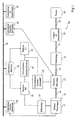
- the hybrid vehicle 10 comprises a heat engine 11 associated with a flywheel 12.
- a cooling system not shown, ensures the cooling of the engine 11 by the circulation of a cooling fluid, for example water.
- An electric machine 13 is coupled to the drive shaft 14.
- the drive shaft 14 is connected to a clutch 16 which, when it is actuated, couples the motor shaft 14 to an input shaft 17 of a transmission chain 18.
- the transmission chain 18 comprises, for example, a gearbox and a divider bridge.
- the rotational speed of the output shaft 19 of the transmission chain 18 corresponds to the rotational speed of the input shaft 17 multiplied by the overall reduction ratio of the chain 18.
- the output shaft 19 is connected to the wheels 20 of the vehicle.
- the gearbox can be a conventional manual gearbox, a robotic gearbox, an automatic gearbox, a continuously variable gearbox, etc.
- the clutch 16 may, depending on the type of gearbox, be automatic or actuated by the driver.
- the hybrid vehicle 10 may comprise on the exhaust line for exhausting the exhaust gas of the heat engine 11 a catalyst not shown.
- the electrical machine 13 is connected to a high-voltage battery 22 via a DC-to-DC converter 24.
- the electric machine 13 can operate as an alternator and charge the high-voltage battery 22 and provide the on-board network, or operate as an electric motor powered by the high voltage battery 22 to drive the motor shaft 14.
- the high-voltage battery 22 is connected to a low-voltage battery 26 via a DC-DC converter 28.
- the DC-DC converter 28 can be adapted to limit the intensity of the current supplied by the high-voltage battery 22. This limit may be a function of the voltages and the temperatures of the batteries 22, 26.
- the low-voltage battery 26 supplies a low-voltage on-board vehicle network (not shown) for the supply of conventional equipment of the vehicle 10 (for example the air conditioning, wiping, heating, etc.).
- the low-voltage battery 26 also supplies a conventional starter 27 that can drive the motor shaft 14.
- the high-voltage battery 22 can possibly supply power to a high-voltage on-board power supply network.
- the low voltage battery 26 has a mean voltage of 12 volts
- the high voltage battery 22 is a NimH type power battery (Nickel-metal-Hydride) average voltage of 42 volts.
- the hybrid vehicle 10 comprises several computers 30, 32, 34, 36 which control the various elements of the hybrid vehicle.
- the computers 30, 32, 34, 36 can exchange data with each other via a data exchange bus 38.
- a control computer 30 for controlling the heat engine 11 is adapted to control, for example, the injection into the combustion chambers of the heat engine 11 from operating parameters of the heat engine 11.
- a control computer 32 for controlling the electric machine 13 is adapted to transmit to the electric machine 13 a torque command from operating parameters of the electric machine 13.
- a computer 34 for monitoring the batteries 22, 26 is adapted, from operating parameters of the high voltage batteries 22 and low voltage 26, to, inter alia, emit an alarm signal when certain conditions of good operation of the batteries 22, 26 are not completed.
- a supervision computer 36 can control the computers 30, 32, 34 for the purpose of providing particular services some of which are described below.
- the supervision computer 36 can control the control computer 32 for controlling the electric machine 13 to activate or deactivate the DC-DC converter 28 and the DC-AC converter 24 of the electrical machine 13.
- the supervision computer 36 receives in in addition to a signal emitted by the control computer 30 for controlling the heat engine 11 representative of the temperature of the cooling water of the thermal engine 11, hereafter called engine water temperature.
- the engine water temperature is measured in the direction of flow of the water downstream of the heat engine 11.
- the supervision computer 36 further receives a signal indicating that a start of the engine 11 is requested by the engine. driver.
- a signal can be, for example, issued by a sensor indicating that a key operated by the driver is in a specific position, or a start button present on the driving position of the vehicle in the case of a vehicle without a key etc.
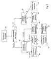
- the figure 2 represents the various steps of an embodiment of the method according to the invention for starting the heat engine 11 of the vehicle 10.
- step 40 the supervision computer 36 detects an action exerted on the vehicle key by the driver.
- step 41 the supervision computer 36 determines the engine water temperature and compares it with a threshold temperature.
- step 42 corresponding to a motor water temperature greater than a threshold temperature of -1 ° C, the supervision computer 36 determines whether the electric machine 13 is operational. If yes, the process continues in step 43 and in the negative in step 44.
- step 43 the supervision computer 36 controls the starting of the heat engine 11 by means of the electric machine 13, powered by the high voltage battery 22, which rotates the motor shaft 14.
- the control of the electric machine 13 is obtained by a torque instruction supplied by the supervision computer 36, according to a speed reference of the thermal machine 11 supplied by the engine 30 thermal engine.
- the electric machine 13 rotates the shaft 14 of the heat engine 11 to a determined speed.
- the heat engine computer 30 commands a maximum injection, then regulates the injection so that the speed of the engine 11 is stabilized at an idle speed.
- step 44 the supervision computer 36 controls the starting of the heat engine 11 by means of the starter 27.
- step 45 corresponding to a motor water temperature less than or equal to -1 ° C, the supervision computer 36 determines whether the starter 27 is operational. If so, and if the engine water temperature is below a threshold temperature of -24 ° C, the process continues at step 46. If yes, and the engine water temperature is higher or at -24 ° C, the process continues at step 47. If not, and if the engine water temperature is above a threshold temperature of -8 ° C, the process proceeds to step 48 In the negative, and if the engine water temperature is below a threshold temperature of -8 ° C, there is no attempt to start.
- step 46 the supervision computer 36 controls the starting of the heat engine 11 with the aid of the starter 27.
- the DC-DC converter 28 is deactivated.
- the starter 27 is therefore powered only by the low voltage battery 26.
- step 47 the supervision computer 36 controls the electric machine calculator 32 to activate the DC-DC converter 28 between the high-voltage batteries 22 and the low-voltage batteries 26 and determines whether activation of the DC-DC converter 28 has been successful. If so, the method continues in step 49. If not, the start takes place without assistance of the high-voltage battery 22.
- step 49 the supervision computer 36 starts the engine 11 by means of the starter 27.
- the DC-DC converter 28 is activated.
- the starter 27 is powered by the low-voltage battery 26 which can receive electrical energy supplied by the high-voltage battery 22.
- the starter 27 drives in rotating the shaft 14 of the heat engine 11 to a determined speed.
- the heat engine computer 30 controls a maximum injection, then regulates the injection so that the speed of the engine 11 is stabilized at an idle speed.
- step 48 the supervision computer 36 determines whether the electric machine 13 is operational. If yes, the process proceeds to step 50. If no, there is no start attempt.
- step 50 the supervision computer 36 controls the start of the heat engine 11 with the aid of the electric machine 13.
- the electric machine 13 is powered only by the high voltage battery 22.
- the supervision computer 36 provides the driver, via an interface present on the dashboard, a signal indicating that the start of the engine 11 has failed.
- the temperature of thermal engine water 11 is used as a selection criterion of the starting member of the engine 11 since it is relatively insensitive to sudden changes in outside temperature, and is representative of the actual temperature of the engine 11.
- the present invention makes it possible to ensure the most favorable conditions for starting the heat engine 11 of a hybrid vehicle series 10 despite low engine temperatures 11.
- the temperature is between -24 ° C and -1 ° C
- the degradation of the properties of the high voltage battery 22 and the electric machine 13 and the increase of the resistive torque of the heat engine 11 are such that a start of the engine 11 with the electric machine 11 may fail.
- the starting is then provided by the starter 27, and the high voltage battery 22 assists the low voltage battery 26, via the DC-DC converter 28, for the starter power supply 27.
- the intensity required at the high battery voltage 22, for the power supply of the starter 27 remains much lower than that provided by the low-voltage battery 26, given the ratios of the voltages at the terminals of the DC-DC converter 24.
- the current requirement of the starter 27 is of the order of 200 A at its terminals, the current supplied by the low voltage battery 26 will be of the order of 100 A and that provided by the high voltage battery 22 will be in the order of 25 A.
- a hysteresis cycle is implemented around the threshold temperatures to avoid unstable operation of the supervision computer 36 when the engine water temperature is close to a threshold temperature.
- the starter 27 is then selected for starting the heat engine 11 when the temperature decreases, for example, below -3 ° C and the electric machine 13 is selected when the temperature increases beyond + 1 ° C.
- the DC-DC converter 28 is not activated when the temperature decreases, for example, below -24 ° C, and the DC-DC converter 28 is activated when the temperature increases beyond -21 ° vs.
- the start is forced to the electric machine 13 when the temperature increases, for example, beyond -5 ° C, and there is no attempt to start when the temperature decreases below -9 ° C.
- the computer 34 for monitoring the batteries 22, 26 transmits an alarm signal on the data bus 38 when the temperature of the high voltage battery 22 is lower than a determined temperature and / or when the state of charge of the high voltage battery 22 is lower than a determined state of charge.
- the calculator electrical machine 32 emits an alarm, on the data bus 38, during a malfunction of the electric machine 13.
- the supervision computer 36 checks whether it has received alarms from the computer 34 batteries or the calculator 32 electric machine. If not, the process proceeds to step 41 as previously described. If so, the heat engine 11 is started with the starter 27 powered by the low voltage battery 26. If the starter is not operational, then no attempt to start the engine 11 is performed, and the engine of Supervision 36 provides the driver with a signal that the start of the engine 11 has failed.
Landscapes
- Engineering & Computer Science (AREA)
- Chemical & Material Sciences (AREA)
- Combustion & Propulsion (AREA)
- Mechanical Engineering (AREA)
- Transportation (AREA)
- Automation & Control Theory (AREA)
- General Engineering & Computer Science (AREA)
- Power Engineering (AREA)
- Hybrid Electric Vehicles (AREA)
- Control Of Vehicle Engines Or Engines For Specific Uses (AREA)
- Combined Controls Of Internal Combustion Engines (AREA)
- Electric Propulsion And Braking For Vehicles (AREA)
Description
- La présente invention concerne un procédé et un dispositif de démarrage d'un moteur thermique d'un véhicule hybride série.
- Un véhicule hybride série comporte un moteur thermique couplé en série avec une machine électrique. Le moteur thermique et la machine électrique peuvent fournir chacun un couple sur l'arbre du moteur thermique pour l'entraînement des roues du véhicule.
- La machine électrique est reliée à une batterie. Alimentée par la batterie, la machine électrique se comporte comme un moteur électrique et fournit un couple qui s'ajoute au couple du moteur thermique. La machine électrique peut également fournir un couple qui s'oppose au couple du moteur thermique. Elle se comporte alors comme un alternateur, charge la batterie et fournit le réseau de bord.
- La machine électrique assiste le moteur thermique dans ses différentes phases de fonctionnement et permet d'améliorer les prestations du moteur thermique et globalement de diminuer la consommation en carburant du moteur thermique. En particulier, le moteur thermique est généralement démarré au moyen de la machine électrique. Par exemple, la machine électrique peut entraîner en rotation l'arbre du moteur thermique jusqu'à un régime déterminé. A ce moment, un calculateur de contrôle de l'injection du moteur thermique commande une injection maximale de carburant dans les chambres de combustion du moteur thermique, puis régule l'injection pour que le régime du moteur thermique se stabilise à un régime de ralenti.
- Au démarrage du moteur thermique, celui-ci présente un couple résistif qui diminue lorsque la température du moteur thermique augmente. A titre d'exemple, pour un moteur diesel classique, pour des températures proches de -25°C, on peut atteindre des couples résistifs de l'ordre de 200 Nm.
- La
publication EP 1 101 649 A2 décrit le démarrage d'un moteur en sélectionnant entre la machine électrique et un démarreur. - Pour des températures faibles, la batterie alimentant la machine électrique peut ne plus fournir la puissance nécessaire pour que la machine électrique produise un couple suffisant pour l'entraînement du moteur thermique. Dans ce cas, le démarrage du moteur thermique peut être compromis.
- La présente invention vise à proposer un procédé et un dispositif de démarrage du moteur thermique permettant d'assurer le démarrage du moteur thermique aux faibles températures.
- Pour atteindre cet objet, la présente invention prévoit un procédé de démarrage d'un moteur thermique d'un véhicule hybride, ledit moteur thermique étant susceptible de fournir un couple moteur à un arbre moteur relié aux roues du véhicule, une machine électrique étant couplée à l'arbre moteur et fournissant un couple d'assistance à l'arbre moteur de même sens ou opposé au couple moteur, comportant les étapes consistant à comparer une température représentative de la température du moteur thermique à un premier seuil ; et entraîner le moteur thermique par la machine électrique, si la température représentative est supérieure au premier seuil, ou par un démarreur distinct de la machine électrique, si la température représentative est inférieure au premier seuil,
- le procédé comprenant en outre les étapes consistant à comparer la température représentative à un second seuil, inférieur au premier seuil ; et alimenter le démarreur par une première batterie, si la température représentative est inférieure au second seuil, ou par l'association de la première batterie et d'une seconde batterie, normalement dédiée à l'alimentation de la machine électrique, si la température représentative est comprise entre le second seuil et le premier seuil.
- Selon un mode de réalisation de l'invention, le premier seuil dépend du sens de variation de la température représentative.
- Selon un mode de réalisation de l'invention, le second seuil dépend du sens de variation de la température représentative.
- Selon un mode de réalisation de l'invention, la température représentative est la température d'un liquide de refroidissement du moteur thermique.
- La présente invention prévoit également un véhicule hybride comprenant un moteur thermique susceptible de fournir un couple moteur à un arbre moteur relié aux roues du véhicule, et une machine électrique couplée à l'arbre moteur et fournissant un couple d'assistance audit arbre moteur de même sens ou opposé au couple moteur, comportant un démarreur pouvant être couplé temporairement à l'arbre moteur, un moyen de détermination d'une température représentative de la température du moteur thermique, et un moyen de sélection adapté à sélectionner, pour entraîner l'arbre moteur lors du démarrage du moteur thermique, la machine électrique si la température représentative est supérieure à un premier seuil, ou le démarreur si la température représentative est inférieure au premier seuil,
- le démarreur étant alimenté par une première batterie d'une première tension nominale, la machine électrique étant alimentée par une seconde batterie d'une seconde tension nominale supérieure à la première tension nominale, la seconde batterie étant reliée au démarreur par l'intermédiaire d'un convertisseur de tension, et le moyen de sélection active le convertisseur de tension de façon que la seconde batterie alimente le démarreur avec la première batterie si la température représentative est inférieure au premier seuil et supérieure à un second seuil inférieur au premier seuil, et désactive le convertisseur de tension si la température représentative est inférieure au second seuil.
- Selon un mode de réalisation de l'invention, un moyen de détection est adapté à transmettre au moyen de sélection un signal indiquant si le démarreur est opérationnel, le moyen de sélection sélectionnant systématiquement la machine électrique pour entraîner l'arbre moteur lors du démarrage du moteur thermique si le signal émis par le moyen de détection indique que le démarreur n'est pas opérationnel.
- Selon un mode de réalisation de l'invention, le moteur thermique est refroidi par la circulation d'un liquide de refroidissement, la température représentative étant la température du liquide de refroidissement
- Cet objet, ces caractéristiques et avantages, ainsi que d'autres de la présente invention seront exposés en détail dans la description suivante de modes de réalisation particuliers faite à titre non-limitatif en relation avec les figures jointes parmi lesquelles :
- la
figure 1 représente, de façon schématique, un exemple d'architecture d'un véhicule hybride série ; et - la
figure 2 représente un exemple de réalisation, sous forme d'organigramme, du procédé selon l'invention de démarrage de moteur thermique. - Comme cela est représenté sur la
figure 1 , le véhicule hybride 10 comprend un moteur thermique 11 associé à un volant moteur 12. Un système de refroidissement, non représenté, assure le refroidissement du moteur thermique 11 par la circulation d'un fluide de refroidissement, par exemple de l'eau. Une machine électrique 13 est couplée sur l'arbre moteur 14. L'arbre moteur 14 est relié à un embrayage 16 qui, lorsqu'il est actionné, couple l'arbre moteur 14 à un arbre d'entrée 17 d'une chaîne de transmission 18. La chaîne de transmission 18 comprend, par exemple, une boîte de vitesses et un pont diviseur. La vitesse de rotation de l'arbre de sortie 19 de la chaîne de transmission 18 correspond à la vitesse de rotation de l'arbre d'entrée 17 multipliée par le rapport de réduction global de la chaîne 18. L'arbre de sortie 19 est relié aux roues 20 du véhicule. La boîte de vitesses peut être une boîte de vitesses manuelle classique, une boîte robotisée, une boîte automatique, une boîte continûment variable, etc. L'embrayage 16 peut, selon le type de boîte de vitesses, être automatique ou actionné par le conducteur. Le véhicule hybride 10 peut comporter sur la ligne d'échappement pour l'évacuation des gaz d'échappement du moteur thermique 11 un catalyseur non représenté. - La machine électrique 13 est reliée à une batterie haute tension 22 par l'intermédiaire d'un convertisseur continu-alternatif 24. La machine électrique 13 peut fonctionner comme un alternateur et charger la batterie haute tension 22 et fournir le réseau de bord, ou bien fonctionner comme un moteur électrique alimenté par la batterie haute tension 22 pour entraîner l'arbre moteur 14.
- La batterie haute tension 22 est reliée à une batterie basse tension 26 par l'intermédiaire d'un convertisseur continu-continu 28. Le convertisseur continu-continu 28 peut être adapté à limiter l'intensité du courant fourni par la batterie haute tension 22. Cette limite peut être fonction des voltages et des températures des batteries 22, 26. La batterie basse tension 26 alimente un réseau de bord à basse tension du véhicule (non représenté) pour l'alimentation d'équipements classiques du véhicule 10 (par exemple la climatisation, l'essuyage, le chauffage, etc.). La batterie basse tension 26 alimente également un démarreur classique 27 pouvant entraîner l'arbre moteur 14. La batterie haute tension 22 peut éventuellement alimenter un réseau de bord à haute tension pour l'alimentation de certains équipements spécifiques du véhicule qui demandent une puissance élevée, comme par exemple des résistances de chauffage, une direction assistée, le chauffage électrique du catalyseur, etc. A titre d'exemple, la batterie basse tension 26 présente une tension moyenne de 12 volts, et la batterie haute tension 22 est une batterie de puissance de type NimH (Nickel-métal-Hydrure) de tension moyenne de 42 volts.
- Le véhicule hybride 10 comporte plusieurs calculateurs 30, 32, 34, 36 qui commandent les différents éléments du véhicule hybride. Les calculateurs 30, 32, 34, 36 peuvent échanger entre eux des données par l'intermédiaire d'un bus d'échange de données 38.
- Un calculateur 30 de contrôle du moteur thermique 11 est adapté à commander par exemple l'injection dans les chambres de combustion du moteur thermique 11 à partir de paramètres de fonctionnement du moteur thermique 11.
- Un calculateur 32 de contrôle de la machine électrique 13 est adapté à transmettre à la machine électrique 13 une commande de couple à partir de paramètres de fonctionnement de la machine électrique 13.
- Un calculateur 34 de contrôle des batteries 22, 26 est adapté, à partir de paramètres de fonctionnement des batteries haute tension 22 et basse tension 26, à, entre autres, émettre un signal d'alarme lorsque certaines conditions de bon fonctionnement des batteries 22, 26 ne sont pas remplies.
- Un calculateur 36 de supervision peut commander les calculateurs 30, 32, 34 dans le but d'assurer des prestations particulières dont certaines sont décrites par la suite. En particulier, le calculateur 36 de supervision peut commander le calculateur 32 de contrôle de la machine électrique 13 pour activer ou désactiver le convertisseur continu-continu 28 et le convertisseur continu-alternatif 24 de la machine électrique 13. Le calculateur 36 de supervision reçoit en outre un signal émis par le calculateur 30 de contrôle du moteur thermique 11 représentatif de la température de l'eau de refroidissement du moteur thermique 11, appelée par la suite température d'eau moteur. De préférence, la température d'eau moteur est mesurée selon le sens de circulation de l'eau en aval du moteur thermique 11. Le calculateur 36 de supervision reçoit en outre un signal indiquant qu'un démarrage du moteur thermique 11 est demandé par le conducteur. Un tel signal peut être, par exemple, émis par un capteur indiquant qu'une clé actionnée par le conducteur est dans une position spécifique, ou un bouton de démarrage présent sur le poste de conduite du véhicule dans le cas d'un véhicule sans clé, etc.
- La
figure 2 représente les différentes étapes d'un mode de réalisation du procédé selon l'invention de démarrage du moteur thermique 11 du véhicule 10. - A l'étape 40, le calculateur de supervision 36 détecte une action exercée sur la clé du véhicule par le conducteur.
- A l'étape 41, le calculateur de supervision 36 détermine la température d'eau moteur et la compare à une température de seuil.
- A l'étape 42, correspondant à une température d'eau moteur supérieure à une température de seuil de -1°C, le calculateur de supervision 36 détermine si la machine électrique 13 est opérationnelle. Dans l'affirmative, le procédé continue à l'étape 43 et dans la négative à l'étape 44.
- A l'étape 43, le calculateur de supervision 36 commande le démarrage du moteur thermique 11 au moyen de la machine électrique 13, alimentée par la batterie haute tension 22, qui entraîne en rotation l'arbre moteur 14. La commande de la machine électrique 13 est obtenue par une consigne de couple fournie par le calculateur 36 de supervision, en fonction d'une consigne de régime de la machine thermique 11 fournie par le calculateur 30 moteur thermique. A titre d'exemple, la machine électrique 13 entraîne en rotation l'arbre 14 du moteur thermique 11 jusqu'à un régime déterminé. A ce moment, le calculateur 30 moteur thermique commande une injection maximale, puis régule l'injection pour que le régime du moteur thermique 11 se stabilise à un régime de ralenti.
- A l'étape 44, le calculateur de supervision 36 commande le démarrage du moteur thermique 11 au moyen du démarreur 27.
- A l'étape 45, correspondant à une température d'eau moteur inférieure ou égale à -1°C, le calculateur de supervision 36 détermine si le démarreur 27 est opérationnel. Dans l'affirmative, et si la température d'eau moteur est inférieure à une température de seuil de -24°C, le procédé continue à l'étape 46. Dans l'affirmative, et si la température d'eau moteur est supérieure ou égale à -24°C, le procédé continue à l'étape 47. Dans la négative, et si la température d'eau moteur est supérieure à une température de seuil de -8°C, le procédé continue à l'étape 48. Dans la négative, et si la température d'eau moteur est inférieure à une température de seuil de -8°C, il n'y a pas de tentative de démarrage.
- A l'étape 46, le calculateur de supervision 36 commande le démarrage du moteur thermique 11 à l'aide du démarreur 27. Le convertisseur continu-continu 28 est désactivé. Le démarreur 27 est donc alimenté uniquement par la batterie basse tension 26.
- A l'étape 47, le calculateur de supervision 36 commande le calculateur machine électrique 32 pour activer le convertisseur continu-continu 28 entre les batteries haute tension 22 et basse tension 26 et détermine si l'activation du convertisseur continu-continu 28 a réussi. Dans l'affirmative, le procédé continue à l'étape 49. Dans la négative, le démarrage a lieu sans assistance de la batterie haute tension 22.
- A l'étape 49, le calculateur de supervision 36 effectue le démarrage du moteur thermique 11 au moyen du démarreur 27. Le convertisseur continu-continu 28 est activé. Le démarreur 27 est alimenté par la batterie basse tension 26 qui peut recevoir de l'énergie électrique fournie par la batterie haute tension 22. A titre d'exemple, le démarreur 27 entraîne en rotation l'arbre 14 du moteur thermique 11 jusqu'à un régime déterminé. A ce moment, le calculateur 30 moteur thermique commande une injection maximale, puis régule l'injection pour que le régime du moteur thermique 11 se stabilise à un régime de ralenti.
- A l'étape 48, le calculateur de supervision 36 détermine si la machine électrique 13 est opérationnelle. Dans l'affirmative, le procédé continue à l'étape 50. Dans la négative, il n'y a pas de tentative de démarrage.
- A l'étape 50, le calculateur de supervision 36 commande le démarrage de la machine thermique 11 à l'aide de la machine électrique 13. La machine électrique 13 est alimentée uniquement par la batterie haute tension 22. De façon classique, si au bout d'une durée déterminée, le moteur thermique 11 n'a pas démarré (ceci pouvant être détecté par une mesure du régime du moteur thermique 11), le calculateur de supervision 36 fournit au conducteur, par l'intermédiaire d'une interface présente sur le tableau de bord, un signal indiquant que le démarrage du moteur thermique 11 a échoué.
- La température d'eau moteur thermique 11 est utilisée comme critère de sélection de l'organe de démarrage du moteur thermique 11 puisqu'elle est relativement peu sensible aux brusques variations de température extérieure, et est représentative de la température réelle du moteur thermique 11.
- La présente invention permet d'assurer les conditions les plus favorables pour le démarrage du moteur thermique 11 d'un véhicule hybride série 10 malgré des températures de moteur thermique 11 basses.
- Dans le cas où la température est comprise entre -24°C et -1°C, on considère que les dégradations des propriétés de la batterie haute tension 22 et de la machine électrique 13 et l'augmentation du couple résistif du moteur thermique 11 sont telles qu'un démarrage du moteur thermique 11 avec la machine électrique 11 risque d'échouer. Le démarrage est alors assuré par le démarreur 27, et la batterie haute tension 22 assiste la batterie basse tension 26, par l'intermédiaire du convertisseur continu-continu 28, pour l'alimentation du démarreur 27. Bien que les propriétés de la batterie haute tension 22 soient dégradées à des températures aussi faibles, l'intensité demandée à la batterie haute tension 22, pour l'alimentation du démarreur 27, reste très inférieure à celle fournie par la batterie basse tension 26, étant donné les rapports des tensions aux bornes du convertisesur continu-continu 24. A titre d'exemple, pour un rapport de tension d'environ 4, si le besoin en courant du démarreur 27 est de l'ordre de 200 A à ses bornes, le courant fourni par la batterie basse tension 26 sera de l'ordre de 100 A et celui fourni par la batterie haute tension 22 sera de l'ordre de 25 A.
- Selon une variante de l'invention, on met en oeuvre un cycle à hystérésis autour des températures de seuil pour éviter un fonctionnement instable du calculateur de supervision 36 lorsque la température d'eau moteur est voisine d'une température de seuil. Le démarreur 27 est alors sélectionné pour le démarrage du moteur thermique 11 lorsque la température diminue, par exemple, en deçà de -3°C et la machine électrique 13 est sélectionnée lorsque la température augmente au delà de +1°C. De façon analogue, le convertisseur continu-continu 28 n'est pas activé lorsque la température diminue, par exemple, en deçà de -24°C, et le convertisseur continu-continu 28 est activé lorsque la température augmente au delà de -21°C. En outre, lors d'un dysfonctionnement du démarreur 27, le démarrage est forcé à la machine électrique 13 lorsque la température augmente, par exemple, au delà de -5°C, et il n'y a pas de tentative de démarrage lorsque la température diminue en deçà de -9°C.
- Selon une variante de l'invention, le calculateur 34 de contrôle des batteries 22, 26 émet un signal d'alarme, sur le bus de données 38, lorsque la température de la batterie haute tension 22 est inférieure à une température déterminée et/ou lorsque l'état de charge de la batterie haute tension 22 est inférieur à un état de charge déterminé. De plus, le calculateur machine électrique 32 émet une alarme, sur le bus de données 38, lors d'un dysfonctionnement de la machine électrique 13. Avant l'étape 41, le calculateur de supervision 36 vérifie s'il a reçu des alarmes du calculateur 34 batteries ou du calculateur 32 machine électrique. Dans la négative, le procédé continue à l'étape 41 comme cela a été précédemment décrit. Dans l'affirmative, le moteur thermique 11 est démarré avec le démarreur 27 alimenté par la batterie basse tension 26. Si le démarreur n'est pas opérationnel, alors aucune tentative de démarrage du moteur thermique 11 n'est réalisée, et le calculateur de supervision 36 fournit au conducteur un signal indiquant que le démarrage du moteur thermique 11 a échoué.
- Bien entendu, la présente invention est susceptible de diverses variantes et modifications qui apparaîtront à l'homme de l'art. En particulier, on a décrit un certain nombre de calculateurs distincts recevant chacun des signaux particuliers et réalisant chacun des actions spécifiques. Il est clair que ce nombre pourrait être différent, un unique calculateur pouvant, par exemple, remplir le rôle de plusieurs calculateurs précédemment décrits.
Claims (7)
- Procédé de démarrage d'un moteur thermique (11) d'un véhicule hybride (10), ledit moteur thermique étant susceptible de fournir un couple moteur à un arbre moteur (14) relié aux roues (20) du véhicule, une machine électrique (13) étant couplée à l'arbre moteur et fournissant un couple d'assistance à l'arbre moteur de même sens ou opposé au couple moteur, comportant les étapes suivantes :- comparer une température représentative de la température du moteur thermique à un premier seuil ; et- entraîner le moteur thermique par la machine électrique, si la température représentative est supérieure au premier seuil, ou par un démarreur (27) distinct de la machine électrique, si la température représentative est inférieure au premier seuil ;- comparer la température représentative à un second seuil, inférieur au premier seuil ; et- alimenter le démarreur (27) par une première batterie (26), si la température représentative est inférieure au second seuil, ou par l'association de la première batterie et d'une seconde batterie (22), normalement dédiée à l'alimentation de la machine électrique (13), si la température représentative est comprise entre le second seuil et le premier seuil.
- Procédé selon la revendication 1, dans lequel le premier seuil dépend du sens de variation de la température représentative.
- Procédé selon la revendication 1, dans lequel le second seuil dépend du sens de variation de la température représentative.
- Procédé selon la revendication 1, dans lequel la température représentative est la température d'un liquide de refroidissement du moteur thermique (11).
- Véhicule hybride (10) comprenant un moteur thermique (11) susceptible de fournir un couple moteur à un arbre moteur (14) relié aux roues (20) du véhicule, et une machine électrique (13) couplée à l'arbre moteur et fournissant un couple d'assistance audit arbre moteur de même sens ou opposé au couple moteur, comportant un démarreur (27) pouvant être couplé temporairement à l'arbre moteur, un moyen de détermination d'une température représentative de la température du moteur thermique, et un moyen de sélection (36) adapté à sélectionner, pour entraîner l'arbre moteur lors du démarrage du moteur thermique, la machine électrique si la température représentative est supérieure à un premier seuil, ou le démarreur si la température représentative est inférieure au premier seuil, et caractérisé en ce que le démarreur (27) est alimenté par une première batterie (26) d'une première tension nominale, la machine électrique étant alimentée par une seconde batterie (22) d'une seconde tension nominale supérieure à la première tension nominale, la seconde batterie étant reliée au démarreur par l'intermédiaire d'un convertisseur de tension (28), le moyen de sélection (36) activant le convertisseur de tension de façon que la seconde batterie alimente le démarreur avec la première batterie si la température représentative est inférieure au premier seuil et supérieure à un second seuil inférieur au premier seuil, et désactivant le convertisseur de tension si la température représentative est inférieure au second seuil.
- Véhicule hybride (10) selon la revendication 5, dans lequel un moyen de détection est adapté à transmettre au moyen de sélection (36) un signal indiquant si le démarreur (27) est opérationnel, le moyen de sélection sélectionnant systématiquement la machine électrique (13) pour entraîner l'arbre moteur (14) lors du démarrage du moteur thermique (11) si le signal émis par le moyen de détection indique que le démarreur n'est pas opérationnel.
- Véhicule hybride (10) selon la revendication 5, dans lequel le moteur thermique (11) est refroidi par la circulation d'un liquide de refroidissement, la température représentative étant la température du liquide de refroidissement.
Applications Claiming Priority (2)
| Application Number | Priority Date | Filing Date | Title |
|---|---|---|---|
| FR0206917 | 2002-06-05 | ||
| FR0206917A FR2840654B1 (fr) | 2002-06-05 | 2002-06-05 | Procede et dispositif de demarrage d'un moteur thermique dans un vehicule hybride serie |
Publications (2)
| Publication Number | Publication Date |
|---|---|
| EP1369285A1 EP1369285A1 (fr) | 2003-12-10 |
| EP1369285B1 true EP1369285B1 (fr) | 2009-10-28 |
Family
ID=29433322
Family Applications (1)
| Application Number | Title | Priority Date | Filing Date |
|---|---|---|---|
| EP03354051A Expired - Lifetime EP1369285B1 (fr) | 2002-06-05 | 2003-06-04 | Procédé et dispositif de démarrage d'un moteur thermique dans un véhicule hybride série |
Country Status (5)
| Country | Link |
|---|---|
| EP (1) | EP1369285B1 (fr) |
| AT (1) | ATE446887T1 (fr) |
| DE (1) | DE60329807D1 (fr) |
| ES (1) | ES2333708T3 (fr) |
| FR (1) | FR2840654B1 (fr) |
Cited By (3)
| Publication number | Priority date | Publication date | Assignee | Title |
|---|---|---|---|---|
| DE102010048388A1 (de) * | 2010-10-13 | 2012-04-19 | Audi Ag | Fahrzeug mit einem Hybridantrieb |
| DE102015117886A1 (de) | 2015-10-21 | 2017-04-27 | Dr. Ing. H.C. F. Porsche Aktiengesellschaft | Verfahren zum Starten einer Verbrennungskraftmaschine eines Hybridfahrzeugs und Hybridfahrzeug |
| DE102016007133A1 (de) | 2016-06-10 | 2017-12-14 | Audi Ag | Steuervorrichtung und Verfahren zum Betreiben eines Kraftfahrzeugs mit einem Verbrennungsmotor und mit zumindest zwei elektrischen Startereinheiten für den Verbrennungsmotor |
Families Citing this family (14)
| Publication number | Priority date | Publication date | Assignee | Title |
|---|---|---|---|---|
| US20080264374A1 (en) * | 2007-04-30 | 2008-10-30 | Caterpillar Inc. | Fail-safe starter control system |
| FR2918125B1 (fr) * | 2007-06-29 | 2009-10-09 | Valeo Equip Electr Moteur | Procede et dispositif de commande d'un systeme de demarrage d'un vehicule motorise mettant en oeuvre une architecture du type dit arret-relance automatique du moteur |
| JP5263078B2 (ja) | 2009-08-26 | 2013-08-14 | 株式会社デンソー | 車両用制御装置 |
| FR2955901B1 (fr) * | 2010-02-03 | 2016-01-01 | Peugeot Citroen Automobiles Sa | Procede de demarrage d'un moteur thermique d'un vehicule automobile comprenant un calculateur |
| FR2966205B1 (fr) * | 2010-10-19 | 2018-01-12 | Psa Automobiles Sa. | Procede pour la mise en œuvre d'un dispositif de demarrage equipant un moteur d'un vehicule automobile |
| JP5817136B2 (ja) * | 2011-02-16 | 2015-11-18 | 日産自動車株式会社 | エンジンの始動装置の保護装置 |
| FR3005624B1 (fr) * | 2013-05-16 | 2016-02-19 | Peugeot Citroen Automobiles Sa | Procede de securisation du demarrage du moteur thermique d'un vehicule hybride comprenant deux moyens de demarrage |
| GB2523080A (en) * | 2014-02-12 | 2015-08-19 | Ford Global Tech Llc | An apparatus and method for starting an engine |
| CN105539172A (zh) * | 2015-12-15 | 2016-05-04 | 苏州贝多环保技术有限公司 | 一种针对混合动力电动汽车的电池充、放电控制方法 |
| FR3057523B1 (fr) * | 2016-10-18 | 2018-11-30 | Peugeot Citroen Automobiles Sa | Procede de demarrage d'un moteur thermique d'un groupe motopropulseur d'un vehicule, notamment automobile" |
| CN114701477B (zh) * | 2021-05-20 | 2025-02-21 | 长城汽车股份有限公司 | 混合动力汽车低温启动控制方法及控制系统 |
| JP7559741B2 (ja) * | 2021-12-02 | 2024-10-02 | トヨタ自動車株式会社 | 制御装置 |
| IT202200018462A1 (it) * | 2022-09-12 | 2024-03-12 | Ferrari Spa | Veicolo stradale provvisto di un convertitore elettronico di potenza dc-dc e corrispondente metodo di controllo |
| CN118046885B (zh) * | 2022-11-17 | 2025-12-19 | 比亚迪股份有限公司 | 发动机控制方法、混合动力车辆及存储介质 |
Family Cites Families (5)
| Publication number | Priority date | Publication date | Assignee | Title |
|---|---|---|---|---|
| DE19645943A1 (de) * | 1996-11-07 | 1998-05-14 | Bosch Gmbh Robert | Startereinheit für eine Brennkraftmaschine |
| JP3285531B2 (ja) * | 1998-03-20 | 2002-05-27 | 三菱電機株式会社 | モータジェネレータ搭載エンジンの始動装置 |
| JP2001065437A (ja) * | 1999-08-25 | 2001-03-16 | Honda Motor Co Ltd | ハイブリッド車両の制御装置 |
| JP3410056B2 (ja) * | 1999-11-19 | 2003-05-26 | トヨタ自動車株式会社 | 車両のエンジン始動制御装置 |
| JP3381708B2 (ja) * | 2000-05-02 | 2003-03-04 | トヨタ自動車株式会社 | 車両、電源系制御装置、電源系を制御する方法および車両の始動時制御方法 |
-
2002
- 2002-06-05 FR FR0206917A patent/FR2840654B1/fr not_active Expired - Fee Related
-
2003
- 2003-06-04 AT AT03354051T patent/ATE446887T1/de not_active IP Right Cessation
- 2003-06-04 ES ES03354051T patent/ES2333708T3/es not_active Expired - Lifetime
- 2003-06-04 EP EP03354051A patent/EP1369285B1/fr not_active Expired - Lifetime
- 2003-06-04 DE DE60329807T patent/DE60329807D1/de not_active Expired - Lifetime
Cited By (5)
| Publication number | Priority date | Publication date | Assignee | Title |
|---|---|---|---|---|
| DE102010048388A1 (de) * | 2010-10-13 | 2012-04-19 | Audi Ag | Fahrzeug mit einem Hybridantrieb |
| DE102010048388B4 (de) | 2010-10-13 | 2022-04-14 | Audi Ag | Fahrzeug mit einem Hybridantrieb und Verfahren zum Starten einer Brennkraftmaschine eines Fahrzeugs mit einem Hybridantrieb |
| DE102015117886A1 (de) | 2015-10-21 | 2017-04-27 | Dr. Ing. H.C. F. Porsche Aktiengesellschaft | Verfahren zum Starten einer Verbrennungskraftmaschine eines Hybridfahrzeugs und Hybridfahrzeug |
| DE102016007133A1 (de) | 2016-06-10 | 2017-12-14 | Audi Ag | Steuervorrichtung und Verfahren zum Betreiben eines Kraftfahrzeugs mit einem Verbrennungsmotor und mit zumindest zwei elektrischen Startereinheiten für den Verbrennungsmotor |
| DE102016007133B4 (de) | 2016-06-10 | 2020-01-16 | Audi Ag | Steuervorrichtung und Verfahren zum Betreiben eines Kraftfahrzeugs mit einem Verbrennungsmotor und mit zumindest zwei elektrischen Startereinheiten für den Verbrennungsmotor |
Also Published As
| Publication number | Publication date |
|---|---|
| FR2840654A1 (fr) | 2003-12-12 |
| EP1369285A1 (fr) | 2003-12-10 |
| DE60329807D1 (de) | 2009-12-10 |
| ATE446887T1 (de) | 2009-11-15 |
| FR2840654B1 (fr) | 2005-08-19 |
| ES2333708T3 (es) | 2010-02-26 |
Similar Documents
| Publication | Publication Date | Title |
|---|---|---|
| EP1369285A1 (fr) | Procédé et dispositif de démarrage d'un moteur thermique dans un véhicule hybride série | |
| US6647939B2 (en) | Vehicle engine starting system and method | |
| US8297390B2 (en) | Vehicular system capable of suitably controlling engine speed and gear ratio according to battery charge state | |
| FR2834941A1 (fr) | Appareil de commande pour un dispositif de stockage d'energie dans un vehicule a moteur | |
| EP2719070A2 (fr) | Procede de controle d'un couple resistant d'un alternateur de vehicule automobile, et systeme de mise en oeuvre de ce procede | |
| EP2089630A1 (fr) | Procede de commande d'un dispositif d'arret et de redemarrage automatique d'un moteur thermique | |
| WO2012085392A1 (fr) | Procede de controle d'un dispositif de direction assistee pour vehicule automobile equipe d'un systeme stop & start | |
| FR3027259A1 (fr) | Procede de pilotage et de regulation thermique d'un systeme de prolongation d'autonomie d'un vehicule automobile | |
| US20040084907A1 (en) | Apparatus and method for preventing an overshoot in the rotation speed of an internal-combustion engine | |
| FR3005624A1 (fr) | Procede de securisation du demarrage du moteur thermique d'un vehicule hybride comprenant deux moyens de demarrage | |
| EP2473729A1 (fr) | Procede de commande d'un systeme micro-hybride | |
| EP3313687B1 (fr) | Procédé de gestion de la température d'une batterie d'un véhicule hybride | |
| WO1994017296A1 (fr) | Procede et dispositif de reduction des emissions de gaz nocifs produites par un moteur a combustion interne propulsant un vehicule automobile | |
| EP1431623B1 (fr) | Récupération d'énergie lors d'un changement de rapport montant sur un véhicule hybride série | |
| WO2023036870A1 (fr) | Procédé d'alimentation d'un dispositif de chauffage pour un catalyseur | |
| JP2000145497A (ja) | 動力装置の始動制御装置 | |
| JP4158887B2 (ja) | 電気車の電力供給装置 | |
| EP1161629A1 (fr) | Procede pour l'entrainement d'un moteur thermique de vehicule, notamment automobile, et ensemble formant demarreur pour sa mise en oeuvre | |
| EP1369281A1 (fr) | Procédé et dispositif de supervision du démarrage et de l'arrêt d'un moteur thermique dans un véhicule hybride série | |
| EP2622206A2 (fr) | Procede de gestion de l'arret et du redemarrage automatique d'un moteur thermique de vehicule automobile et vehicule automobile correspondant | |
| EP2628234A1 (fr) | Procede de recharge d'un module supercondensateur d'un vehicule automobile et vehicule automobile correspondant | |
| JP4209364B2 (ja) | 車両用駆動装置 | |
| EP3894251B1 (fr) | Procede de commande du demarrage d'un moteur thermique de vehicule hybride | |
| FR3149929A1 (fr) | Dispositif d’alimentation d’un dispositif de chauffe pour catalyseur et procédé d’alimentation d’un dispositif de chauffe pour catalyseur | |
| WO2022162809A1 (fr) | Procédé de réduction de charge de génération d'énergie électrique et appareil de réduction de charge de génération d'énergie électrique pour moteur à combustion interne pour véhicule |
Legal Events
| Date | Code | Title | Description |
|---|---|---|---|
| PUAI | Public reference made under article 153(3) epc to a published international application that has entered the european phase |
Free format text: ORIGINAL CODE: 0009012 |
|
| AK | Designated contracting states |
Kind code of ref document: A1 Designated state(s): AT BE BG CH CY CZ DE DK EE ES FI FR GB GR HU IE IT LI LU MC NL PT RO SE SI SK TR |
|
| AX | Request for extension of the european patent |
Extension state: AL LT LV MK |
|
| 17P | Request for examination filed |
Effective date: 20040609 |
|
| AKX | Designation fees paid |
Designated state(s): AT BE BG CH CY CZ DE DK EE ES FI FR GB GR HU IE IT LI LU MC NL PT RO SE SI SK TR |
|
| GRAP | Despatch of communication of intention to grant a patent |
Free format text: ORIGINAL CODE: EPIDOSNIGR1 |
|
| RIC1 | Information provided on ipc code assigned before grant |
Ipc: B60W 10/04 20060101AFI20090519BHEP Ipc: B60L 11/12 20060101ALI20090519BHEP Ipc: B60W 20/00 20060101ALI20090519BHEP Ipc: F02N 11/08 20060101ALI20090519BHEP Ipc: F02N 17/00 20060101ALI20090519BHEP Ipc: F02N 17/08 20060101ALI20090519BHEP |
|
| GRAS | Grant fee paid |
Free format text: ORIGINAL CODE: EPIDOSNIGR3 |
|
| GRAA | (expected) grant |
Free format text: ORIGINAL CODE: 0009210 |
|
| AK | Designated contracting states |
Kind code of ref document: B1 Designated state(s): AT BE BG CH CY CZ DE DK EE ES FI FR GB GR HU IE IT LI LU MC NL PT RO SE SI SK TR |
|
| REG | Reference to a national code |
Ref country code: GB Ref legal event code: FG4D Free format text: NOT ENGLISH |
|
| REG | Reference to a national code |
Ref country code: CH Ref legal event code: EP |
|
| REG | Reference to a national code |
Ref country code: IE Ref legal event code: FG4D |
|
| REF | Corresponds to: |
Ref document number: 60329807 Country of ref document: DE Date of ref document: 20091210 Kind code of ref document: P |
|
| REG | Reference to a national code |
Ref country code: ES Ref legal event code: FG2A Ref document number: 2333708 Country of ref document: ES Kind code of ref document: T3 |
|
| REG | Reference to a national code |
Ref country code: GB Ref legal event code: 746 Effective date: 20100215 |
|
| NLV1 | Nl: lapsed or annulled due to failure to fulfill the requirements of art. 29p and 29m of the patents act | ||
| PG25 | Lapsed in a contracting state [announced via postgrant information from national office to epo] |
Ref country code: SE Free format text: LAPSE BECAUSE OF FAILURE TO SUBMIT A TRANSLATION OF THE DESCRIPTION OR TO PAY THE FEE WITHIN THE PRESCRIBED TIME-LIMIT Effective date: 20091028 Ref country code: FI Free format text: LAPSE BECAUSE OF FAILURE TO SUBMIT A TRANSLATION OF THE DESCRIPTION OR TO PAY THE FEE WITHIN THE PRESCRIBED TIME-LIMIT Effective date: 20091028 Ref country code: PT Free format text: LAPSE BECAUSE OF FAILURE TO SUBMIT A TRANSLATION OF THE DESCRIPTION OR TO PAY THE FEE WITHIN THE PRESCRIBED TIME-LIMIT Effective date: 20100301 |
|
| REG | Reference to a national code |
Ref country code: IE Ref legal event code: FD4D |
|
| PG25 | Lapsed in a contracting state [announced via postgrant information from national office to epo] |
Ref country code: CY Free format text: LAPSE BECAUSE OF FAILURE TO SUBMIT A TRANSLATION OF THE DESCRIPTION OR TO PAY THE FEE WITHIN THE PRESCRIBED TIME-LIMIT Effective date: 20091028 Ref country code: SI Free format text: LAPSE BECAUSE OF FAILURE TO SUBMIT A TRANSLATION OF THE DESCRIPTION OR TO PAY THE FEE WITHIN THE PRESCRIBED TIME-LIMIT Effective date: 20091028 |
|
| PG25 | Lapsed in a contracting state [announced via postgrant information from national office to epo] |
Ref country code: AT Free format text: LAPSE BECAUSE OF FAILURE TO SUBMIT A TRANSLATION OF THE DESCRIPTION OR TO PAY THE FEE WITHIN THE PRESCRIBED TIME-LIMIT Effective date: 20091028 |
|
| PG25 | Lapsed in a contracting state [announced via postgrant information from national office to epo] |
Ref country code: DK Free format text: LAPSE BECAUSE OF FAILURE TO SUBMIT A TRANSLATION OF THE DESCRIPTION OR TO PAY THE FEE WITHIN THE PRESCRIBED TIME-LIMIT Effective date: 20091028 Ref country code: EE Free format text: LAPSE BECAUSE OF FAILURE TO SUBMIT A TRANSLATION OF THE DESCRIPTION OR TO PAY THE FEE WITHIN THE PRESCRIBED TIME-LIMIT Effective date: 20091028 Ref country code: RO Free format text: LAPSE BECAUSE OF FAILURE TO SUBMIT A TRANSLATION OF THE DESCRIPTION OR TO PAY THE FEE WITHIN THE PRESCRIBED TIME-LIMIT Effective date: 20091028 Ref country code: BG Free format text: LAPSE BECAUSE OF FAILURE TO SUBMIT A TRANSLATION OF THE DESCRIPTION OR TO PAY THE FEE WITHIN THE PRESCRIBED TIME-LIMIT Effective date: 20100128 Ref country code: IE Free format text: LAPSE BECAUSE OF FAILURE TO SUBMIT A TRANSLATION OF THE DESCRIPTION OR TO PAY THE FEE WITHIN THE PRESCRIBED TIME-LIMIT Effective date: 20091028 |
|
| PG25 | Lapsed in a contracting state [announced via postgrant information from national office to epo] |
Ref country code: SK Free format text: LAPSE BECAUSE OF FAILURE TO SUBMIT A TRANSLATION OF THE DESCRIPTION OR TO PAY THE FEE WITHIN THE PRESCRIBED TIME-LIMIT Effective date: 20091028 Ref country code: CZ Free format text: LAPSE BECAUSE OF FAILURE TO SUBMIT A TRANSLATION OF THE DESCRIPTION OR TO PAY THE FEE WITHIN THE PRESCRIBED TIME-LIMIT Effective date: 20091028 |
|
| PLBE | No opposition filed within time limit |
Free format text: ORIGINAL CODE: 0009261 |
|
| STAA | Information on the status of an ep patent application or granted ep patent |
Free format text: STATUS: NO OPPOSITION FILED WITHIN TIME LIMIT |
|
| 26N | No opposition filed |
Effective date: 20100729 |
|
| PG25 | Lapsed in a contracting state [announced via postgrant information from national office to epo] |
Ref country code: GR Free format text: LAPSE BECAUSE OF FAILURE TO SUBMIT A TRANSLATION OF THE DESCRIPTION OR TO PAY THE FEE WITHIN THE PRESCRIBED TIME-LIMIT Effective date: 20100129 |
|
| BERE | Be: lapsed |
Owner name: PEUGEOT CITROEN AUTOMOBILES SA Effective date: 20100630 |
|
| PG25 | Lapsed in a contracting state [announced via postgrant information from national office to epo] |
Ref country code: MC Free format text: LAPSE BECAUSE OF NON-PAYMENT OF DUE FEES Effective date: 20100630 |
|
| REG | Reference to a national code |
Ref country code: CH Ref legal event code: PL |
|
| REG | Reference to a national code |
Ref country code: ES Ref legal event code: GC2A Effective date: 20110203 |
|
| PG25 | Lapsed in a contracting state [announced via postgrant information from national office to epo] |
Ref country code: LI Free format text: LAPSE BECAUSE OF NON-PAYMENT OF DUE FEES Effective date: 20100630 Ref country code: CH Free format text: LAPSE BECAUSE OF NON-PAYMENT OF DUE FEES Effective date: 20100630 |
|
| PG25 | Lapsed in a contracting state [announced via postgrant information from national office to epo] |
Ref country code: BE Free format text: LAPSE BECAUSE OF NON-PAYMENT OF DUE FEES Effective date: 20100630 |
|
| PGFP | Annual fee paid to national office [announced via postgrant information from national office to epo] |
Ref country code: GB Payment date: 20110606 Year of fee payment: 9 |
|
| PGFP | Annual fee paid to national office [announced via postgrant information from national office to epo] |
Ref country code: ES Payment date: 20110525 Year of fee payment: 9 |
|
| REG | Reference to a national code |
Ref country code: DE Ref legal event code: R079 Ref document number: 60329807 Country of ref document: DE Free format text: PREVIOUS MAIN CLASS: B60W0010040000 Ipc: B60W0020000000 Effective date: 20120202 |
|
| PG25 | Lapsed in a contracting state [announced via postgrant information from national office to epo] |
Ref country code: HU Free format text: LAPSE BECAUSE OF FAILURE TO SUBMIT A TRANSLATION OF THE DESCRIPTION OR TO PAY THE FEE WITHIN THE PRESCRIBED TIME-LIMIT Effective date: 20100429 Ref country code: LU Free format text: LAPSE BECAUSE OF NON-PAYMENT OF DUE FEES Effective date: 20100604 Ref country code: NL Free format text: LAPSE BECAUSE OF FAILURE TO SUBMIT A TRANSLATION OF THE DESCRIPTION OR TO PAY THE FEE WITHIN THE PRESCRIBED TIME-LIMIT Effective date: 20091028 |
|
| PGFP | Annual fee paid to national office [announced via postgrant information from national office to epo] |
Ref country code: IT Payment date: 20120526 Year of fee payment: 10 |
|
| PG25 | Lapsed in a contracting state [announced via postgrant information from national office to epo] |
Ref country code: TR Free format text: LAPSE BECAUSE OF FAILURE TO SUBMIT A TRANSLATION OF THE DESCRIPTION OR TO PAY THE FEE WITHIN THE PRESCRIBED TIME-LIMIT Effective date: 20091028 |
|
| GBPC | Gb: european patent ceased through non-payment of renewal fee |
Effective date: 20120604 |
|
| PG25 | Lapsed in a contracting state [announced via postgrant information from national office to epo] |
Ref country code: GB Free format text: LAPSE BECAUSE OF NON-PAYMENT OF DUE FEES Effective date: 20120604 |
|
| REG | Reference to a national code |
Ref country code: ES Ref legal event code: FD2A Effective date: 20131021 |
|
| PG25 | Lapsed in a contracting state [announced via postgrant information from national office to epo] |
Ref country code: ES Free format text: LAPSE BECAUSE OF NON-PAYMENT OF DUE FEES Effective date: 20120605 |
|
| PG25 | Lapsed in a contracting state [announced via postgrant information from national office to epo] |
Ref country code: IT Free format text: LAPSE BECAUSE OF NON-PAYMENT OF DUE FEES Effective date: 20130604 |
|
| REG | Reference to a national code |
Ref country code: FR Ref legal event code: PLFP Year of fee payment: 14 |
|
| REG | Reference to a national code |
Ref country code: FR Ref legal event code: PLFP Year of fee payment: 15 |
|
| REG | Reference to a national code |
Ref country code: FR Ref legal event code: PLFP Year of fee payment: 16 |
|
| REG | Reference to a national code |
Ref country code: FR Ref legal event code: CA Effective date: 20180312 Ref country code: FR Ref legal event code: CD Owner name: PEUGEOT CITROEN AUTOMOBILES SA, FR Effective date: 20180312 |
|
| PGFP | Annual fee paid to national office [announced via postgrant information from national office to epo] |
Ref country code: FR Payment date: 20220519 Year of fee payment: 20 Ref country code: DE Payment date: 20220518 Year of fee payment: 20 |
|
| REG | Reference to a national code |
Ref country code: DE Ref legal event code: R071 Ref document number: 60329807 Country of ref document: DE |