EP1369389A2 - Rohrhalbzeug und Verfahren zur Herstellung von Glasbehältnissen aus einem Rohrhalbzeug - Google Patents
Rohrhalbzeug und Verfahren zur Herstellung von Glasbehältnissen aus einem Rohrhalbzeug Download PDFInfo
- Publication number
- EP1369389A2 EP1369389A2 EP03010246A EP03010246A EP1369389A2 EP 1369389 A2 EP1369389 A2 EP 1369389A2 EP 03010246 A EP03010246 A EP 03010246A EP 03010246 A EP03010246 A EP 03010246A EP 1369389 A2 EP1369389 A2 EP 1369389A2
- Authority
- EP
- European Patent Office
- Prior art keywords
- semi
- tube
- glass
- finished
- end region
- Prior art date
- Legal status (The legal status is an assumption and is not a legal conclusion. Google has not performed a legal analysis and makes no representation as to the accuracy of the status listed.)
- Granted
Links
Images

Classifications
-
- C—CHEMISTRY; METALLURGY
- C03—GLASS; MINERAL OR SLAG WOOL
- C03B—MANUFACTURE, SHAPING, OR SUPPLEMENTARY PROCESSES
- C03B23/00—Re-forming shaped glass
- C03B23/04—Re-forming tubes or rods
- C03B23/09—Reshaping the ends, e.g. as grooves, threads or mouths
- C03B23/099—Reshaping the ends, e.g. as grooves, threads or mouths by fusing, e.g. flame sealing
-
- C—CHEMISTRY; METALLURGY
- C03—GLASS; MINERAL OR SLAG WOOL
- C03B—MANUFACTURE, SHAPING, OR SUPPLEMENTARY PROCESSES
- C03B23/00—Re-forming shaped glass
- C03B23/04—Re-forming tubes or rods
- C03B23/11—Reshaping by drawing without blowing, in combination with separating, e.g. for making ampoules
-
- C—CHEMISTRY; METALLURGY
- C03—GLASS; MINERAL OR SLAG WOOL
- C03B—MANUFACTURE, SHAPING, OR SUPPLEMENTARY PROCESSES
- C03B23/00—Re-forming shaped glass
- C03B23/18—Re-forming and sealing ampoules
Definitions
- the invention relates to a semi-finished tube product for the production of glass containers, in particular glass tube vials, glass ampoules and glass syringes in the pharmaceutical sector, in particular with the features from the generic term of claim 1, further a method for producing glass containers, especially for filling with pharmaceutical products from one Tube semis.
- EP-B-111 710 is a method for producing Glass tube vials previously known from a semi-finished glass tube.
- the Semi-finished glass tube is formed from a continuous strand of glass. For this purpose, a tube length is cut from the glass tube string and on both Ends softened. The softened ends are pulled out axially until the Glass tube coincides in this area and thus closed tube ends be preserved. In the immediate vicinity of one of the two closed A punctiform opening is made in the pipe ends and the prepared one Pipe length in the form of the semi-finished product used in a manufacturing machine and processed into glass vials there.
- the semi-finished tube is vertical Direction used in the manufacturing machines so that the punctiform Opening is in the vertical direction below. At the top end is the pipe wall moderately warmed.
- the pipe length is then above the punctiform opening thermally severed, with the remaining semi-finished tube temporarily forms a floor, which, however, as a result of the building up Overpressure immediately bursts open.
- the mouth of the first Vial shaped.
- the semi-finished tube is then again thermally severed, with the bottom of the first tube at the same time and another bottom is formed from the remaining pipe, which, however, in As a result of the build-up of internal overpressure, it bursts open again immediately.
- This Process steps are repeated on the remaining semi-finished tube, whereby individual tube vials are created, one for pharmaceutical applications have suitable cleanliness.
- the semi-finished tube itself for example, as in DE 82 32 133 U1 described as a tubular semi-finished product closed on both sides by means of a film closable opening can usually be timed offset to the actual manufacture of the glass containers. This are then by a method such as that described in the publication DE-A-27 29 966 is described, packed into tube packs, being in the densest Pack next to and on top of each other from a hood made of flexible material be enclosed. You will then get to the in a double protected state Glass container manufacturer who uses the method already described. To the complete closure of the individual semi-finished tube is also the Vent hole acting punctiform opening through a film again locked.
- This film is designed to be moderately warm softens and then bursts under low pressure or from one material exists, which burns without residue. This makes it for pharmaceutical Applications required purity guaranteed.
- semi-finished tube products are characterized by an increased outlay.
- part of the tube length of the semi-finished tube discarded, namely the part with the vent hole and the part of the tube remaining when subdivided into tube lengths Semi-finished tube with a shorter length than the tube.
- a certain rate of faulty Glass containers only through precise coordination of the individual Process parameters in the manufacture of glass containers can be excluded.
- the invention is therefore based on the object of a method for the production of glass containers, in particular for pharmaceutical applications, for example in the form of glass tube vials, glass ampoules and glass syringes, to create, which is characterized by a high level of economy. It is in particular on optimal use of the entire length of the To park semi-finished products. Furthermore, the manufacturing and control technology To keep the effort in the production of the glass containers as low as possible or should be characterized by a larger tolerance range.
- the semi-finished tube product according to the invention for the production of glass containers, especially suitable for pharmaceutical applications, in particular Glass tube vials, glass ampoules and glass syringes comprise a tube wall with two end regions, the first end region of the tube wall below Formation of a floor is closed. In the area of the first end area is in the tube wall is provided at least one vent hole. This is preferably carried out perpendicular to the tube semi-finished product axis. The diameter this vent hole is preferably in a range from> 0 to ⁇ 1% that of a conventional pipe open on both sides Area. According to the invention, the other, second end region is free of one Closure, i.e. it has an opening or is completely open.
- the open end region advantageously has to begin with glass containers a axial runout of> 0 and ⁇ 1 mm, preferably ⁇ 0.8 mm.
- the semi-finished tube is used in a production machine and processed there to the glass tube containers.
- Semi-finished tube preferably in a vertical arrangement in such a way Manufacturing machines used that the closed end area with the Ventilation opening in the vertical direction is at the top. The second open The end area is then in the vertical direction at the bottom. On the second open End area can be started immediately by heating and the desired mouth shape is formed.
- the length of the Corresponding glass container, distance is then the semi-finished tube, starting from the shaped mouth, thermally severed, with the bottom of the glass container forms this process at the same time.
- This can be flat or in the interior delimited by the pipe wall directed curvature are formed.
- the individual process steps are then repeated continuously on the semi-finished tube, with further Glass containers are created. It is preferred that it is already manufactured Glass tube container removed from the guide of the semi-finished tube, so that remaining semi-finished tube with the now open end area in the position of now removed glass container can be moved. This offers the Advantage that the heating and shaping unit for producing the Mouth does not have to be moved and with the vertical arrangement of the Pipe semi-finished this in the gravity direction by itself this position can take.
- a major advantage of this solution is that one with the production of the glass containers immediately without discarding material from the Semi-finished tube can be started and also because of the always existing vent hole, the pressure conditions in the semi-finished tube slightly are manageable, so that no damage or faulty Glass containers arise due to possible pressure peaks in the semi-finished tube. Furthermore, it can already form a thermal separation during the formation of a Bottom come on the remaining semi-finished tube, it in no way is problematic because the targeted heating of this end area required opening and thus the shape of the mouth can be reworked can. The possibly resulting in the manufacture of the semi-finished tube A disadvantage of an increased particle load at the open end area can be caused by this Processes, especially targeted heating, are compensated again.
- the solution according to the invention thus offers, in particular, the Mass production of glass containers a significant economic Advantage through the use of a semi-finished tube with closed on one side End area and vent hole compared to the known solutions end area closed on both sides and ventilation hole or on one side closed end area without vent hole.
- this is done Automated procedure. This offers the possibility of increased throughput, especially in mass production.
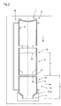
- FIG. 1 illustrates in a schematically highly simplified representation a longitudinal section through a semi-finished tube 1 designed according to the invention, which is used for the production of glass containers 2, which can be designed, for example, in the form of glass vials, glass ampoules or glass syringes, and which are particularly suitable for pharmaceutical applications ,
- the semi-finished tube 1 is shown in longitudinal section. This has two end regions, a first end region 3 and a second end region 4. The first end region 3 is closed.
- a bottom 6 is provided directly at the pipe end 5.
- the floor can, as in the case shown, be arched toward the interior 7 of the semi-finished tube delimited by the wall of the floor.
- a flat design of the base 6, which is not shown here, is also conceivable.
- a vent hole 8 is provided, which is incorporated in the wall 9 of the semi-finished tube 1 and is preferably in the vicinity of the bottom 6.
- the vent hole is made perpendicular to the pipe center axis R M. This is also arranged in the first end region 3.
- the semi-finished tube 1 is made from a continuous glass tube strand finite length won.
- the glass tubing becomes a Semi-finished tube 1 forming tube element with length 1 separated. That included resulting pipe element is open at both end areas.
- the one of the Both open end regions of the tube length 1 are then softened and by means of a Extending force acting in the axial direction until the tubular element in this Area coincides and a first planer or slightly arched inward Bottom 6 is formed.
- the second end area, which is in the finished Semi-finished tube 1 then corresponds to the open end region 4, remains untreated.
- the required run-flat at the open end area is achieved by the separation, which usually takes place thermally, from the glass tube strand.
- the vent hole 8 is then machined. This will preferably attached by means of a stitch burner.
- the resulting semi-finished tube 1 is then used to carry out the The inventive method in a manufacturing machine 10 preferably used such that the closed end region 3 with the Vent hole 8 is in the vertical direction above.
- the production takes place starting from the open end area 4.
- the Pipe wall 9 warmed moderately, for example with a device 11, wherein by means of a device 12 the desired mouth for the glass container 2 is formed.
- the device for heating 11 and the device for Shaping 12 can also be combined into one unit.
- the semi-finished tube 1 is then thermally cut, where the cut at the resulting end region 13 of the then Glass container 2 forming tube section 14 forms a bottom 15. That so resulting glass container 2 is correspondingly from the production machine 10 removed in the direction of the arrow and the semi-finished tube is moved in the vertical direction led down or falls down.
- the Pressure conditions in the semi-finished tube 1 remain due to the existing Vent hole 8 manageable.
- the resulting contour of the Glass tube vial 2 ' is shown by a broken line.
Landscapes
- Chemical & Material Sciences (AREA)
- Engineering & Computer Science (AREA)
- Materials Engineering (AREA)
- Organic Chemistry (AREA)
- Re-Forming, After-Treatment, Cutting And Transporting Of Glass Products (AREA)
- Medical Preparation Storing Or Oral Administration Devices (AREA)
- Infusion, Injection, And Reservoir Apparatuses (AREA)
- Glass Compositions (AREA)
- Lining Or Joining Of Plastics Or The Like (AREA)
Abstract
Description
- Figur 1
- verdeutlicht anhand eines Längsschnittes ein erfindungsgemäß gestaltetes Rohrhalbzeug;
- Figur 2
- verdeutlicht in schematisch stark vereinfachter Darstellung das Grundprinzip des Verfahrens zur Herstellung von Glasbehältnissen, insbesondere mit Eignung für den Einsatz im pharmazeutischen Bereich.
- 1
- Rohrhalbzeug
- 2, 2'
- Glasbehältnis
- 3
- erster Endbereich
- 4
- zweiter Endbereich
- 5
- Rohrende
- 6
- Boden
- 7
- Innenraum
- 8
- Entlüftungsbohrung
- 9
- Wandung
- 10
- Fertigungsautomat
- 11
- Einrichtung zur Erwärmung
- 12
- Einrichtung zur Formgebung
- 13, 13'
- Endbereich
- 14,14'
- Vorteilstück
- 15,15'
- Boden
- RM
- Rohrmittenachse
- a, a'
- Abstand
Claims (12)
- Rohrhalbzeug (1) zur Herstellung von Glasbehältnissen (2, 2'), insbesondere Glasrohrfläschchen, Glasampullen oder Glasspritzen, insbesondere mit Eignung für pharmazeutische Anwendungen mit einer Rohrwandung (9), umfassend zwei Endbereiche (3, 4) - einen ersten Endbereich (3) und einen zweiten Endbereich (4) - wobei der erste Endbereich (3) unter Bildung eines Bodens (6) verschlossen ist und eine Entlüftungsbohrung (8), die im Bereich des Endbereiches (3) in der Rohrwandung (9) eingearbeitet ist, dadurch gekennzeichnet, dass das den zweiten Endbereich (4) charakterisierende Rohrende eine Öffnung aufweist.
- Rohrhalbzeug (1) nach Anspruch 1, dadurch gekennzeichnet, dass die Öffnung am zweiten Endbereich (4) dem Innendurchmesser der Rohrwandung (9) entspricht.
- Rohrhalbzeug (1) nach einem der Ansprüche 1 oder 2, dadurch gekennzeichnet, dass die Rohrwandung (9) am zweiten Endbereich (4) einen Planverlauf von > 0 und ≤ 0,8 mm aufweist.
- Rohrhalbzeug (1) nach einem der Ansprüche 1 bis 3, dadurch gekennzeichnet, dass der im ersten Endbereich (3) gebildete Boden (6) plan oder aber zum durch die Rohrwandung (9) begrenzten Innenraum (7) hin gewölbt ausgeführt ist.
- Verfahren zur Herstellung von Glasbehältnissen (2, 2'), insbesondere Glasfläschchen, Glasampullen oder Glasspritzen aus einem Rohrhalbzeug (1) gemäß einem der Ansprüche 1 bis 4, bei welchem das Rohrhalbzeug (1) in einen Fertigungsautomaten eingesetzt wird und dort zu Glasbehältnissen (2, 2') verarbeitet wird.
- Verfahren nach Anspruch 5, gekennzeichnet durch die folgenden Merkmale:6.1 das Rohrhalbzeug (1) wird in vertikaler Anordnung mit der Entlüftungsöffnung (8) nach oben in den Fertigungsautomaten (10) eingesetzt;6.2 das Rohrhalbzeug (1) wird am offenen Endbereich (4) erwärmt und die geforderte Mündung für das Glasbehältnis (2, 2') geformt;6.3 in einem der Länge des Glasbehältnisses entsprechenden Abstand von der entstehenden Mündung wird das Rohrhalbzeug (1) durchtrennt, wobei sich gleichzeitig der Boden (15, 15') des Glasbehältnisses (2, 2') bildet;6.4 die Verfahrensschritte 6.1 bis 6.3 werden wiederholt.
- Verfahren nach Anspruch 6, dadurch gekennzeichnet, dass die Durchtrennung des Rohrhalbzeuges thermisch erfolgt.
- Verfahren nach einem der Ansprüche 6 oder 7, gekennzeichnet durch die folgenden Merkmale:8.1 das Glasbehältnis (2, 2') wird nach Bildung des Bodens (15, 15') aus dem Bereich der Führungsachse der Rohrhalbzeuges (1) im Fertigungsautomaten (10) entfernt;8.2 das Rohrhalbzeug (1) wird entlang der Führungsachse um den Abstand der Länge des entfernten Glasbehältnisses geführt.
- Verfahren nach Anspruch 8, dadurch gekennzeichnet, dass bei vertikaler Anordnung des Rohrhalbzeuges (1) im Fertigungsautomaten (10) der Führungsvorgang durch die Schwerkraft selbsttätig erfolgt.
- Verfahren nach einem der Ansprüche 6 bis 9, dadurch gekennzeichnet, dass die Erwärmung des offenen Endbereiches (4) gesteuert wird.
- Verfahren nach einem der Ansprüche 5 bis 10, dadurch gekennzeichnet, dass die Fertigung der einzelnen Glasbehältnisse (2, 2') zeitlich aufeinanderfolgend kontinuierlich erfolgt.
- Verfahren nach einem der Ansprüche 5 bis 11, dadurch gekennzeichnet, dass die Herstellung der Glasbehältnisse (2, 2') automatisiert erfolgt.
Applications Claiming Priority (2)
| Application Number | Priority Date | Filing Date | Title |
|---|---|---|---|
| DE10224833A DE10224833B4 (de) | 2002-06-05 | 2002-06-05 | Rohrhalbzeug und Verfahren zur Herstellung von Glasbehältnissen aus einem Rohrhalbzeug |
| DE10224833 | 2002-06-05 |
Publications (3)
| Publication Number | Publication Date |
|---|---|
| EP1369389A2 true EP1369389A2 (de) | 2003-12-10 |
| EP1369389A3 EP1369389A3 (de) | 2004-12-01 |
| EP1369389B1 EP1369389B1 (de) | 2007-02-28 |
Family
ID=29432640
Family Applications (1)
| Application Number | Title | Priority Date | Filing Date |
|---|---|---|---|
| EP03010246A Expired - Lifetime EP1369389B1 (de) | 2002-06-05 | 2003-05-07 | Verfahren zur Herstellung von Glasbehältnissen aus einem Rohrhalbzeug |
Country Status (14)
| Country | Link |
|---|---|
| US (1) | US20040007280A1 (de) |
| EP (1) | EP1369389B1 (de) |
| JP (1) | JP2004010475A (de) |
| KR (1) | KR100689879B1 (de) |
| CN (1) | CN1467166A (de) |
| AT (1) | ATE355258T1 (de) |
| BR (1) | BR0301665A (de) |
| DE (2) | DE10224833B4 (de) |
| EG (1) | EG23559A (de) |
| ES (1) | ES2281579T3 (de) |
| MX (1) | MXPA03004393A (de) |
| PL (1) | PL360399A1 (de) |
| RU (1) | RU2299186C2 (de) |
| UA (1) | UA77661C2 (de) |
Cited By (3)
| Publication number | Priority date | Publication date | Assignee | Title |
|---|---|---|---|---|
| DE102011013623A1 (de) | 2011-03-02 | 2012-09-06 | Schott Ag | Verfahren zur Herstellung einer für die Fertigung von Ampullen und Fläschchen geeigneten, verbesserten Glasröhre, Vorrichtung zur Herstellung sowie Rohrhalbzeug |
| DE102018109820A1 (de) | 2018-04-24 | 2019-10-24 | Schott Ag | Verfahren und Vorrichtung zur Herstellung von Glashohlkörperprodukten sowie Glashohlkörperprodukte und deren Verwendung |
| EP4201896A1 (de) * | 2021-12-22 | 2023-06-28 | Schott Ag | Glasrohr für pharmazeutische behälter und verfahren zur herstellung eines glasrohrs |
Families Citing this family (16)
| Publication number | Priority date | Publication date | Assignee | Title |
|---|---|---|---|---|
| US7578109B2 (en) * | 2004-08-31 | 2009-08-25 | Gossamer Space Frames | Space frames and connection node arrangement for them |
| JP4671971B2 (ja) | 2004-12-28 | 2011-04-20 | パナソニック株式会社 | 無線通信装置及び無線通信方法 |
| CN101475303B (zh) * | 2009-01-22 | 2011-10-26 | 河北科技大学 | 真空安瓿熔封机 |
| CN101717183B (zh) * | 2009-12-07 | 2012-01-11 | 浙江新康药用玻璃有限公司 | 提高管制玻璃瓶化学稳定性的方法 |
| DE102011051143B3 (de) | 2011-06-17 | 2012-09-20 | Vitajuwel Gmbh | Fertigungsverfahren für einen Glasbehälter |
| CN104055674A (zh) * | 2013-03-19 | 2014-09-24 | 丹阳双峰玻璃有限公司 | 药用玻璃管 |
| PE20151989A1 (es) * | 2013-05-30 | 2016-01-20 | Dalwick Continental Corp | Metodo para la fabricacion de envases de vidrio para uso farmaceutico |
| JP6801289B2 (ja) * | 2016-08-16 | 2020-12-16 | 日本電気硝子株式会社 | ガラス管の製造方法 |
| US11014701B2 (en) | 2018-05-18 | 2021-05-25 | Schott Ag | Glass container with an improved bottom geometry |
| CN110498109B (zh) * | 2018-05-18 | 2021-08-03 | 肖特股份有限公司 | 具有改进的底部几何结构的玻璃容器 |
| JP6755028B2 (ja) * | 2018-12-19 | 2020-09-16 | ネクサス株式会社 | 石英バイアル瓶の製造方法 |
| JP7490954B2 (ja) * | 2019-12-19 | 2024-05-28 | 日本電気硝子株式会社 | ガラス物品の製造方法、及びガラス物品の製造装置 |
| DE102020114903A1 (de) * | 2020-06-04 | 2021-12-09 | Gerresheimer Bünde Gmbh | Verfahren und Anlage zum Herstellen eines Glasbehältnisses sowie Glasbehältnis |
| JP6781418B2 (ja) * | 2020-07-20 | 2020-11-04 | ネクサス株式会社 | 石英バイアル瓶の製造方法 |
| CN112159085B (zh) * | 2020-09-15 | 2022-05-27 | 中建材玻璃新材料研究院集团有限公司 | 一种硼硅玻璃管切割封口一体化设备及工艺方法 |
| CN114873550B (zh) * | 2022-05-23 | 2024-02-23 | 四川高晟医药包材科技有限公司 | 一种安瓿瓶的生产加工装置及方法 |
Family Cites Families (14)
| Publication number | Priority date | Publication date | Assignee | Title |
|---|---|---|---|---|
| DE8232133U1 (de) * | 1983-04-07 | Schott-Ruhrglas GmbH, 8580 Bayreuth | Glasröhre für die Fertigung von Ampullen und Rohrfläschchen | |
| US1348062A (en) * | 1919-05-05 | 1920-07-27 | Jennie M Shook | Cream-separating milk-bottle |
| US1411990A (en) * | 1920-01-02 | 1922-04-04 | Corson Alfred Mearle | Measuring and dispensing device |
| SU12212A1 (ru) * | 1927-03-30 | 1929-12-31 | Мейер Ф. | Способ изготовлени стекл нных ампул и т.п. изделий |
| FR1172478A (fr) * | 1957-04-25 | 1959-02-11 | Canne de verre pour la fabrication des ampoules et son mode de préparation | |
| GB1084252A (de) * | 1964-02-12 | |||
| US3719463A (en) * | 1971-08-10 | 1973-03-06 | Owens Illinois Inc | Method of opening ampules in a non-contaminating manner |
| DE2729966C2 (de) * | 1977-07-02 | 1985-10-03 | Schott-Ruhrglas GmbH, 8580 Bayreuth | Gebinde von Röhren aus sprödem Material |
| EP0111710B1 (de) * | 1982-11-16 | 1989-08-30 | Schott-Ruhrglas Gmbh | Verfahren zum Herstellen von Rohrfläschchen |
| CH659451A5 (de) * | 1982-12-13 | 1987-01-30 | Ferag Ag | Mehrblaettriges, aus ineinanderliegenden gefalzten bogen bestehendes druckprodukt. |
| SU1172892A1 (ru) * | 1983-05-26 | 1985-08-15 | Специальное Проектно-Конструкторское Бюро Медицинской Промышленности Ленинградского Научно-Производственного Объединения "Прогресс" | Способ изготовлени стекл нных изделий |
| DE3341313A1 (de) * | 1983-11-15 | 1985-05-23 | Schott-Ruhrglas GmbH, 8580 Bayreuth | Verfahren zur herstellung einer fuer die ampullen- und flaeschenfertigung geeigneten glasroehre |
| US4762241A (en) * | 1987-02-05 | 1988-08-09 | Lang Richard R | Container with supplemental opening for extracting contents |
| US20020074367A1 (en) * | 2000-12-18 | 2002-06-20 | Kevin Kawakita | Gravity-fed liquid chemical dispenser bottle |
-
2002
- 2002-06-05 DE DE10224833A patent/DE10224833B4/de not_active Expired - Lifetime
- 2002-12-20 CN CNA021542961A patent/CN1467166A/zh active Pending
-
2003
- 2003-05-07 AT AT03010246T patent/ATE355258T1/de not_active IP Right Cessation
- 2003-05-07 DE DE50306627T patent/DE50306627D1/de not_active Expired - Fee Related
- 2003-05-07 ES ES03010246T patent/ES2281579T3/es not_active Expired - Lifetime
- 2003-05-07 EP EP03010246A patent/EP1369389B1/de not_active Expired - Lifetime
- 2003-05-08 UA UA2003054172A patent/UA77661C2/uk unknown
- 2003-05-19 US US10/441,268 patent/US20040007280A1/en not_active Abandoned
- 2003-05-19 MX MXPA03004393A patent/MXPA03004393A/es not_active Application Discontinuation
- 2003-05-27 KR KR1020030033632A patent/KR100689879B1/ko not_active Expired - Fee Related
- 2003-05-29 PL PL03360399A patent/PL360399A1/xx not_active Application Discontinuation
- 2003-05-29 JP JP2003153319A patent/JP2004010475A/ja active Pending
- 2003-06-03 BR BR0301665-0A patent/BR0301665A/pt not_active Application Discontinuation
- 2003-06-03 EG EG2003060527A patent/EG23559A/xx active
- 2003-06-04 RU RU2003116609/03A patent/RU2299186C2/ru active
Cited By (5)
| Publication number | Priority date | Publication date | Assignee | Title |
|---|---|---|---|---|
| DE102011013623A1 (de) | 2011-03-02 | 2012-09-06 | Schott Ag | Verfahren zur Herstellung einer für die Fertigung von Ampullen und Fläschchen geeigneten, verbesserten Glasröhre, Vorrichtung zur Herstellung sowie Rohrhalbzeug |
| DE102011013623B4 (de) * | 2011-03-02 | 2017-08-31 | Schott Ag | Verfahren zur Herstellung einer für die Fertigung von Ampullen und Fläschchen geeigneten Glasröhre und Vorrichtung zur Herstellung |
| DE102018109820A1 (de) | 2018-04-24 | 2019-10-24 | Schott Ag | Verfahren und Vorrichtung zur Herstellung von Glashohlkörperprodukten sowie Glashohlkörperprodukte und deren Verwendung |
| EP4201896A1 (de) * | 2021-12-22 | 2023-06-28 | Schott Ag | Glasrohr für pharmazeutische behälter und verfahren zur herstellung eines glasrohrs |
| US12391425B2 (en) | 2021-12-22 | 2025-08-19 | Schott Ag | Glass tube for pharmaceutical containers and process for the production of a glass tube |
Also Published As
| Publication number | Publication date |
|---|---|
| BR0301665A (pt) | 2004-08-24 |
| ATE355258T1 (de) | 2006-03-15 |
| MXPA03004393A (es) | 2004-09-03 |
| DE10224833A1 (de) | 2004-01-15 |
| EP1369389B1 (de) | 2007-02-28 |
| EP1369389A3 (de) | 2004-12-01 |
| JP2004010475A (ja) | 2004-01-15 |
| KR100689879B1 (ko) | 2007-03-08 |
| EG23559A (en) | 2006-09-18 |
| DE10224833B4 (de) | 2005-04-14 |
| RU2299186C2 (ru) | 2007-05-20 |
| KR20030093982A (ko) | 2003-12-11 |
| ES2281579T3 (es) | 2007-10-01 |
| PL360399A1 (en) | 2003-12-15 |
| US20040007280A1 (en) | 2004-01-15 |
| UA77661C2 (en) | 2007-01-15 |
| CN1467166A (zh) | 2004-01-14 |
| DE50306627D1 (de) | 2007-04-12 |
Similar Documents
| Publication | Publication Date | Title |
|---|---|---|
| EP1369389A2 (de) | Rohrhalbzeug und Verfahren zur Herstellung von Glasbehältnissen aus einem Rohrhalbzeug | |
| DE69725207T3 (de) | Hermetisch verschlossener Behälter mit zerbrechbarem Band und Verschlussansätzen sowie Verfahren und Vorrichtung zum Herstellen desselben | |
| EP3587365A2 (de) | Vorrichtung und verfahren zum thermischen behandeln eines ringförmigen bereichs einer inneren oberfläche eines aus einem borosilikat-rohrglas hergestellten glasbehälters | |
| EP1343693B1 (de) | Verfahren und vorrichtung zum herstellen und befüllen von behältern | |
| DE3735909A1 (de) | Tropferflasche und verfahren zu ihrer herstellung | |
| DE102007015078A1 (de) | Vorrichtung zum Minimieren des Sauerstoffgehaltes | |
| DE1954421A1 (de) | Vorrichtung zur Herstellung von Schichtkoerpern | |
| EP0111710B1 (de) | Verfahren zum Herstellen von Rohrfläschchen | |
| DE102011015666B4 (de) | Verfahren sowie Vorrichtung zur Herstellung von Behältern | |
| DE2032976C3 (de) | Verfahren und Vorrichtung zum Abtrennen von durch das Hohlkörper-Blasverfahren bedingten, mit dem erzeugten Hohlkörper zwangsläufig zusammenhängenden Elementen | |
| EP1708923B1 (de) | Verfahren und vorrichtung zum herstellen und befüllen von behältern | |
| DE102011013623B4 (de) | Verfahren zur Herstellung einer für die Fertigung von Ampullen und Fläschchen geeigneten Glasröhre und Vorrichtung zur Herstellung | |
| EP2987622A1 (de) | Formfüllmaschine und Verfahren zum Ausformen und Füllen von Behältern | |
| DE19649030C2 (de) | Verfahren und Vorrichtung zur Herstellung eines Verschlußknopfes für Flaschen-Bügelverschlüsse oder -Hebelverschlüsse aus Glas | |
| DD202523A5 (de) | Verfahren zum herstellen von rohrflaeschchen und ampullen | |
| EP2108501B1 (de) | Verfahren und Vorrichtung zum Herstellen von Kunststoffbehältnissen | |
| DE102006039175B3 (de) | Vorrichtung und Verfahren zur Formung von Glasartikeln | |
| DE102006042506B4 (de) | Verfahren und Vorrichtung zur Herstellung einer Karton/Kunststoff-Verbundverpackung | |
| DE10337388B4 (de) | Vertikal-Tiegelziehverfahren zur Herstellung eines zylinderförmigen Quarzglaskörpers und Vorrichtung zur Durchführung des Verfahrens | |
| DE102010034474B4 (de) | Verfahren zum Herstellen eines Behälters aus Glas aus der Schmelze | |
| DE3021759A1 (de) | Vorrichtung zum biegen und befestigen der kanten eines behaelters fuer landwirtschaftliche produkte | |
| EP1889549A1 (de) | Selbstverfertigung von Zigaretten aus einem Tabakquader | |
| DE1596367C (de) | Schleudergießform fur Tnchterteile rechteckiger Fernsehbildrohrenkolben | |
| DE10235845A1 (de) | Verfahren und Vorrichtung zur Herstellung einer Preform aus thermoplastischem Werkstoff zur Fertigung eines Behälters | |
| DE19815413A1 (de) | Verfahren zur Herstellung einer Verpackung sowie Verpackung hergestellt nach diesem Verfahren |
Legal Events
| Date | Code | Title | Description |
|---|---|---|---|
| PUAI | Public reference made under article 153(3) epc to a published international application that has entered the european phase |
Free format text: ORIGINAL CODE: 0009012 |
|
| 17P | Request for examination filed |
Effective date: 20030507 |
|
| AK | Designated contracting states |
Kind code of ref document: A2 Designated state(s): AT BE BG CH CY CZ DE DK EE ES FI FR GB GR HU IE IT LI LU MC NL PT RO SE SI SK TR |
|
| AX | Request for extension of the european patent |
Extension state: AL LT LV MK |
|
| PUAL | Search report despatched |
Free format text: ORIGINAL CODE: 0009013 |
|
| RAP1 | Party data changed (applicant data changed or rights of an application transferred) |
Owner name: SCHOTT AG |
|
| AK | Designated contracting states |
Kind code of ref document: A3 Designated state(s): AT BE BG CH CY CZ DE DK EE ES FI FR GB GR HU IE IT LI LU MC NL PT RO SE SI SK TR |
|
| AX | Request for extension of the european patent |
Extension state: AL LT LV MK |
|
| 17Q | First examination report despatched |
Effective date: 20050614 |
|
| AKX | Designation fees paid |
Designated state(s): AT BE BG CH CY CZ DE DK EE ES FI FR GB GR HU IE IT LI LU MC NL PT RO SE SI SK TR |
|
| GRAP | Despatch of communication of intention to grant a patent |
Free format text: ORIGINAL CODE: EPIDOSNIGR1 |
|
| RTI1 | Title (correction) |
Free format text: METHOD FOR PRODUCING GLASS CONTAINERS FROM A TUBE PREFORM |
|
| GRAS | Grant fee paid |
Free format text: ORIGINAL CODE: EPIDOSNIGR3 |
|
| GRAA | (expected) grant |
Free format text: ORIGINAL CODE: 0009210 |
|
| AK | Designated contracting states |
Kind code of ref document: B1 Designated state(s): AT BE BG CH CY CZ DE DK EE ES FI FR GB GR HU IE IT LI LU MC NL PT RO SE SI SK TR |
|
| PG25 | Lapsed in a contracting state [announced via postgrant information from national office to epo] |
Ref country code: DK Free format text: LAPSE BECAUSE OF FAILURE TO SUBMIT A TRANSLATION OF THE DESCRIPTION OR TO PAY THE FEE WITHIN THE PRESCRIBED TIME-LIMIT Effective date: 20070228 Ref country code: IE Free format text: LAPSE BECAUSE OF FAILURE TO SUBMIT A TRANSLATION OF THE DESCRIPTION OR TO PAY THE FEE WITHIN THE PRESCRIBED TIME-LIMIT Effective date: 20070228 Ref country code: FI Free format text: LAPSE BECAUSE OF FAILURE TO SUBMIT A TRANSLATION OF THE DESCRIPTION OR TO PAY THE FEE WITHIN THE PRESCRIBED TIME-LIMIT Effective date: 20070228 Ref country code: NL Free format text: LAPSE BECAUSE OF FAILURE TO SUBMIT A TRANSLATION OF THE DESCRIPTION OR TO PAY THE FEE WITHIN THE PRESCRIBED TIME-LIMIT Effective date: 20070228 Ref country code: SI Free format text: LAPSE BECAUSE OF FAILURE TO SUBMIT A TRANSLATION OF THE DESCRIPTION OR TO PAY THE FEE WITHIN THE PRESCRIBED TIME-LIMIT Effective date: 20070228 |
|
| REG | Reference to a national code |
Ref country code: GB Ref legal event code: FG4D Free format text: NOT ENGLISH |
|
| REG | Reference to a national code |
Ref country code: CH Ref legal event code: EP |
|
| REF | Corresponds to: |
Ref document number: 50306627 Country of ref document: DE Date of ref document: 20070412 Kind code of ref document: P |
|
| REG | Reference to a national code |
Ref country code: IE Ref legal event code: FG4D Free format text: LANGUAGE OF EP DOCUMENT: GERMAN |
|
| PG25 | Lapsed in a contracting state [announced via postgrant information from national office to epo] |
Ref country code: BG Free format text: LAPSE BECAUSE OF EXPIRATION OF PROTECTION Effective date: 20070529 |
|
| PG25 | Lapsed in a contracting state [announced via postgrant information from national office to epo] |
Ref country code: SE Free format text: LAPSE BECAUSE OF FAILURE TO SUBMIT A TRANSLATION OF THE DESCRIPTION OR TO PAY THE FEE WITHIN THE PRESCRIBED TIME-LIMIT Effective date: 20070531 |
|
| PG25 | Lapsed in a contracting state [announced via postgrant information from national office to epo] |
Ref country code: PT Free format text: LAPSE BECAUSE OF FAILURE TO SUBMIT A TRANSLATION OF THE DESCRIPTION OR TO PAY THE FEE WITHIN THE PRESCRIBED TIME-LIMIT Effective date: 20070730 |
|
| NLV1 | Nl: lapsed or annulled due to failure to fulfill the requirements of art. 29p and 29m of the patents act | ||
| GBV | Gb: ep patent (uk) treated as always having been void in accordance with gb section 77(7)/1977 [no translation filed] |
Effective date: 20070228 |
|
| REG | Reference to a national code |
Ref country code: ES Ref legal event code: FG2A Ref document number: 2281579 Country of ref document: ES Kind code of ref document: T3 |
|
| REG | Reference to a national code |
Ref country code: IE Ref legal event code: FD4D |
|
| PG25 | Lapsed in a contracting state [announced via postgrant information from national office to epo] |
Ref country code: SK Free format text: LAPSE BECAUSE OF FAILURE TO SUBMIT A TRANSLATION OF THE DESCRIPTION OR TO PAY THE FEE WITHIN THE PRESCRIBED TIME-LIMIT Effective date: 20070228 Ref country code: GB Free format text: LAPSE BECAUSE OF FAILURE TO SUBMIT A TRANSLATION OF THE DESCRIPTION OR TO PAY THE FEE WITHIN THE PRESCRIBED TIME-LIMIT Effective date: 20070228 |
|
| BERE | Be: lapsed |
Owner name: SCHOTT A.G. Effective date: 20070531 |
|
| PG25 | Lapsed in a contracting state [announced via postgrant information from national office to epo] |
Ref country code: CZ Free format text: LAPSE BECAUSE OF FAILURE TO SUBMIT A TRANSLATION OF THE DESCRIPTION OR TO PAY THE FEE WITHIN THE PRESCRIBED TIME-LIMIT Effective date: 20070228 Ref country code: RO Free format text: LAPSE BECAUSE OF FAILURE TO SUBMIT A TRANSLATION OF THE DESCRIPTION OR TO PAY THE FEE WITHIN THE PRESCRIBED TIME-LIMIT Effective date: 20070228 |
|
| PLBE | No opposition filed within time limit |
Free format text: ORIGINAL CODE: 0009261 |
|
| STAA | Information on the status of an ep patent application or granted ep patent |
Free format text: STATUS: NO OPPOSITION FILED WITHIN TIME LIMIT |
|
| REG | Reference to a national code |
Ref country code: CH Ref legal event code: PL |
|
| PG25 | Lapsed in a contracting state [announced via postgrant information from national office to epo] |
Ref country code: MC Free format text: LAPSE BECAUSE OF NON-PAYMENT OF DUE FEES Effective date: 20070531 |
|
| 26N | No opposition filed |
Effective date: 20071129 |
|
| PG25 | Lapsed in a contracting state [announced via postgrant information from national office to epo] |
Ref country code: LI Free format text: LAPSE BECAUSE OF NON-PAYMENT OF DUE FEES Effective date: 20070531 Ref country code: CH Free format text: LAPSE BECAUSE OF NON-PAYMENT OF DUE FEES Effective date: 20070531 |
|
| PG25 | Lapsed in a contracting state [announced via postgrant information from national office to epo] |
Ref country code: BE Free format text: LAPSE BECAUSE OF NON-PAYMENT OF DUE FEES Effective date: 20070531 |
|
| PG25 | Lapsed in a contracting state [announced via postgrant information from national office to epo] |
Ref country code: GR Free format text: LAPSE BECAUSE OF FAILURE TO SUBMIT A TRANSLATION OF THE DESCRIPTION OR TO PAY THE FEE WITHIN THE PRESCRIBED TIME-LIMIT Effective date: 20070529 Ref country code: DE Free format text: LAPSE BECAUSE OF NON-PAYMENT OF DUE FEES Effective date: 20071201 |
|
| PG25 | Lapsed in a contracting state [announced via postgrant information from national office to epo] |
Ref country code: AT Free format text: LAPSE BECAUSE OF NON-PAYMENT OF DUE FEES Effective date: 20070507 |
|
| PG25 | Lapsed in a contracting state [announced via postgrant information from national office to epo] |
Ref country code: EE Free format text: LAPSE BECAUSE OF FAILURE TO SUBMIT A TRANSLATION OF THE DESCRIPTION OR TO PAY THE FEE WITHIN THE PRESCRIBED TIME-LIMIT Effective date: 20070228 |
|
| PG25 | Lapsed in a contracting state [announced via postgrant information from national office to epo] |
Ref country code: CY Free format text: LAPSE BECAUSE OF FAILURE TO SUBMIT A TRANSLATION OF THE DESCRIPTION OR TO PAY THE FEE WITHIN THE PRESCRIBED TIME-LIMIT Effective date: 20070228 |
|
| PG25 | Lapsed in a contracting state [announced via postgrant information from national office to epo] |
Ref country code: LU Free format text: LAPSE BECAUSE OF NON-PAYMENT OF DUE FEES Effective date: 20070507 |
|
| PG25 | Lapsed in a contracting state [announced via postgrant information from national office to epo] |
Ref country code: HU Free format text: LAPSE BECAUSE OF FAILURE TO SUBMIT A TRANSLATION OF THE DESCRIPTION OR TO PAY THE FEE WITHIN THE PRESCRIBED TIME-LIMIT Effective date: 20070901 Ref country code: TR Free format text: LAPSE BECAUSE OF FAILURE TO SUBMIT A TRANSLATION OF THE DESCRIPTION OR TO PAY THE FEE WITHIN THE PRESCRIBED TIME-LIMIT Effective date: 20070228 |
|
| REG | Reference to a national code |
Ref country code: FR Ref legal event code: PLFP Year of fee payment: 14 |
|
| REG | Reference to a national code |
Ref country code: FR Ref legal event code: PLFP Year of fee payment: 15 |
|
| REG | Reference to a national code |
Ref country code: FR Ref legal event code: PLFP Year of fee payment: 16 |
|
| PGFP | Annual fee paid to national office [announced via postgrant information from national office to epo] |
Ref country code: ES Payment date: 20210721 Year of fee payment: 19 |
|
| PGFP | Annual fee paid to national office [announced via postgrant information from national office to epo] |
Ref country code: IT Payment date: 20220524 Year of fee payment: 20 Ref country code: FR Payment date: 20220523 Year of fee payment: 20 |
|
| REG | Reference to a national code |
Ref country code: ES Ref legal event code: FD2A Effective date: 20230627 |
|
| PG25 | Lapsed in a contracting state [announced via postgrant information from national office to epo] |
Ref country code: ES Free format text: LAPSE BECAUSE OF NON-PAYMENT OF DUE FEES Effective date: 20220508 |