EP1369619A2 - Courroie - Google Patents
Courroie Download PDFInfo
- Publication number
- EP1369619A2 EP1369619A2 EP03077623A EP03077623A EP1369619A2 EP 1369619 A2 EP1369619 A2 EP 1369619A2 EP 03077623 A EP03077623 A EP 03077623A EP 03077623 A EP03077623 A EP 03077623A EP 1369619 A2 EP1369619 A2 EP 1369619A2
- Authority
- EP
- European Patent Office
- Prior art keywords
- rings
- ring
- belt
- innermost
- adjacent
- Prior art date
- Legal status (The legal status is an assumption and is not a legal conclusion. Google has not performed a legal analysis and makes no representation as to the accuracy of the status listed.)
- Withdrawn
Links
- 230000005540 biological transmission Effects 0.000 claims abstract description 12
- 239000002184 metal Substances 0.000 claims abstract description 8
- 239000000463 material Substances 0.000 claims description 2
- 241001274660 Modulus Species 0.000 claims 1
- 230000000694 effects Effects 0.000 description 16
- 230000003993 interaction Effects 0.000 description 2
- 238000005452 bending Methods 0.000 description 1
- 238000012790 confirmation Methods 0.000 description 1
- 238000010276 construction Methods 0.000 description 1
- 239000002826 coolant Substances 0.000 description 1
- 230000003247 decreasing effect Effects 0.000 description 1
- 230000009977 dual effect Effects 0.000 description 1
- 230000002349 favourable effect Effects 0.000 description 1
Images

Classifications
-
- F—MECHANICAL ENGINEERING; LIGHTING; HEATING; WEAPONS; BLASTING
- F16—ENGINEERING ELEMENTS AND UNITS; GENERAL MEASURES FOR PRODUCING AND MAINTAINING EFFECTIVE FUNCTIONING OF MACHINES OR INSTALLATIONS; THERMAL INSULATION IN GENERAL
- F16G—BELTS, CABLES, OR ROPES, PREDOMINANTLY USED FOR DRIVING PURPOSES; CHAINS; FITTINGS PREDOMINANTLY USED THEREFOR
- F16G5/00—V-belts, i.e. belts of tapered cross-section
- F16G5/16—V-belts, i.e. belts of tapered cross-section consisting of several parts
-
- F—MECHANICAL ENGINEERING; LIGHTING; HEATING; WEAPONS; BLASTING
- F16—ENGINEERING ELEMENTS AND UNITS; GENERAL MEASURES FOR PRODUCING AND MAINTAINING EFFECTIVE FUNCTIONING OF MACHINES OR INSTALLATIONS; THERMAL INSULATION IN GENERAL
- F16G—BELTS, CABLES, OR ROPES, PREDOMINANTLY USED FOR DRIVING PURPOSES; CHAINS; FITTINGS PREDOMINANTLY USED THEREFOR
- F16G5/00—V-belts, i.e. belts of tapered cross-section
- F16G5/16—V-belts, i.e. belts of tapered cross-section consisting of several parts
- F16G5/163—V-belts, i.e. belts of tapered cross-section consisting of several parts with means allowing lubrication
Definitions
- the present invention relates to a belt for use in a Continuously Variable Transmission as defined by the preamble of claim 1.
- Such a belt is generally known, more in particular from the US patent No. 3720113. Belts satisfying the described characteristics mentioned in this document are known in practice, and prove to perform satisfactorily.
- the set of rings shown by such belts will be described as adjacent rings, alternatively denoted hoops or strips, and adjacent meaning directly adjacent, in other words such that mutual abutment may take place between adjacent rings in a set.
- a problem underlying the invention is how to determine one ore more specific features of a belt related to the endurance thereof.
- One such feature is suggested by US patent No. 4579549, teaching that the innermost ring, alternatively denoted hoop, is subjected to the biggest tensile stress of all the hoops. Decrease of tensile stresses of the innermost hoop is mentioned to enhance the service life thereof and therewith of the belt.
- the document further indicates the hoops of a set to be "superimposed with no clearance between abutting hoops". This indication is in the document explained to mean that each of the hoops has an outer circumference diameter adapted to be equal to, or larger than, an inner circumference diameter of an abutting outer hoop.
- the present invention overcomes the drawbacks of all prior art by prescribing a play of nominal value zero. In this way an even distribution of ring stress over at least the majority of the rings of a set is effected, realising a balanced transfer of tensile stress between each relevant ring. Moreover, the level of tensile stress so realised in any ring of a set is significantly lower than that in the ring with highest tensile stress in any of both known solutions. It will be found that with a belt according to the invention the life time of a belt is increased to such extend that durability may with expediity be exchanged against the level of torque to be transmitted, e.g. the effect may be utilised by applying the essentially same belt in environments with higher torque to be transmitted.
- a favoured embodiment according to the invention requires that the nominal value of zero is realised by a tolerance of 0.00005 times the outer diameter of the inner ring of a relevant pair of rings, plus or minus of said diameter.
- the technical effect of this measure according to the invention is that the differences of lifetime effect will remain within an accepted bandwidth for technically equivalent belts.
- no significant difference in life time can be remarked as a consequence of this measure, since the effect hereof is that the spread of life time consequence of this measure will normally remain within the natural life time spread caused by metal fatigue.
- Yet another preferred embodiment of the invention requires the mutual play between the innermost pair of adjacent rings is of negative value. It is acknowledged by the invention that the innermost ring of a set, as described by US-4579549, "is subjected to both tensile forces and frictional forces". However, as indicated by the measure according to claim 1, the measure subsequently taught by said publication is rejected. Rather, the favoured embodiment applies the idea underlying the present invention to solve the problem of the first ring, i.e. to take account of the tension each ring is individually subjected to.
- the invention is further characterised in that the outermost diameter of the innermost ring is of a value (1-Z) times the inner diameter of the adjacent ring, Z being of a value smaller than 0.0008.
- a technical effect of the so specifically identified range is that the reliability and consistency of the effect of the measure related to the innermost belt is increased, while taking into account further sources of tension specific to the innermost belt, including e.g. so called Hertze tensions originating from the element-ring contacts.
- the value of greater than 0,0001 effects yet a further enhancement. It will be found that, although the parameter Z to some extend varies with the application of a relevant belt, a belt is stressed in conformance with the in-between ring, thus having a conforming life time, when the parameter Z is kept in the above said range.
- a further specific aspect of the invention relates to a belt wherein the mutual play of the outermost pair of adjacent rings is of positive value.
- the technical effect hereof is that compensation is provided for tension sources other than tensile stress, specific to the outer rings, such that the total tension in the outer ring may be brought into conformance with, i.e. will not be higher than, the tension in the further rings of a set.
- An insight underlying this aspect of the invention is that a tension source specific to the outer rings is caused by subjection to intense contact with transverse elements, i.e. with the boundary opposite to the so-called saddle part, at the instant where the belt should escape out of the pulley in which it is to be operated.
- the elements are clamped between the sheaves of a pulley, they tend to rotate therewith. For transmitting force to the other pulley however, the belt and the elements should cross to the other pulley. Thus the elements are pulled out of the sheaves at the instance of leaving the pulley, thereby causing intense contact between the so-called ear part of a transverse element and the outermost ring.
- the inner diameter of the outermost ring is of a value (1 + Y) times the outermost diameter of the adjacent ring, Y being of a value smaller than 0,0004 and preferably greater than 0,00005.
- a particular aspect of the invention is characterised in that the thickness of one or both of the innermost and the outermost ring of the set is significantly less than the nominal thickness of in between rings of the set.
- the invention therefor also relates to a belt for use in a continuously variable transmission, in particular for automotive application, comprising at least one set of nested metal rings, the set interacting with transverse elements provided slidably along the set, and the rings of the set being accommodated with small mutual play between each pair of adjacent rings, whereby the thickness of one or both of the innermost and the outermost ring of the set is significantly less than the nominal thickness of in between rings of the set.
- the invention provides an alternative means of realising an evenly distributed tension level over the rings of a set.
- the insight utilised in this invention is that a smaller thickness realises a lower bending stress in the relevant ring thereby lowering the tension level in said innermost and/or outermost ring, allowing the relevant ring to receive tension from sources specific therefor, without penalty in regard of life time.
- Yet another particular aspect of the invention relates to the measure wherein the material composition of at least one of the innermost and the outermost ring of the set significantly differs from that of the in between rings of the set, such that the elasticity modulus thereof is significantly lower than that of in between positioned rings.
- the invention therefor also relates to a belt, in particular according to any of the preceding claims, for use in a continuously variable transmission, in particular for automotive application, comprising at least one set of nested metal rings, the set interacting with transverse elements provided slidably along the set, and the rings of the set being accommodated with small mutual play between each pair of adjacent rings, whereby the elasticity modulus of one or both of the innermost and the outermost ring of the set is significantly less than the nominal thickness of in between rings of the set.
- the value for thickness and elasticity modulus of said innermost and said outermost ring is at least twenty percent (20%) less than the average value of said parameters at the in-between rings.
- FIG 1 shows schematically a continuous variable transmission (CVT) suitable amongst others for automotive application, with a conveyor belt 1, made up of a carrier in the form of a nested set of endless thin bands 2, otherwise denoted rings 2 and a multitude of separate transverse elements 3, otherwise denoted blocks 3.
- the elements 3 are arranged freely slidably along said carrier 7 in an endless, virtually continuous series.
- the carrier 7, alternatively denoted support and ring set is composed of a number of the in endless bands, alternatively denoted loops or rings.
- the belt 3 runs within the V-shaped groove of the pulleys 1 and 2 with steplessly variable diameter.
- Its elements 6 are provided with inclined contact faces for contacting the sheaves 4 and 5 of said pulleys.
- the pulleys 1 and 2 are provided on shafts P and S respectively. When pinched sufficiently strong between the sheaves of a pulley 1, 2 the belt 3 transmits force from one rotating pulley to the other.
- the elements 6, as seen in cross section preferably have a lower part of which at least one principle side is inclined relative to the upper part at the same side, so that the element 6 becomes thinner towards the side directed to the inner side of the belt. Such a continuous variable transmission is known per se.
- the elements 6 further are provided with generally slightly convex shaped contact faces also denoted saddles for contacting the support 7, in particular the innermost band thereof.
- the belt through the rotation of a driving pulley passes a trajectory with upper and lower predominantly straight parts between the pulleys, and with first and second predominantly circular trajectories, where the belt is clamped by the sheaves of a pulley.
- the carrier 7 may be subjected to highest tensile forces.
- the belt in one straight part may become somewhat buckled due to the elements pushing against each other, thereby virtually forming a metal rod between said pulleys, and having the tendency of splashing apart. This tendency however, is counteracted by the carrier 7, which according to the invention in the push is may be subjected to relatively high tensile stresses.
- high tensile stress may depending on the state of the belt, also occur at the opposite straight part where the belt, i.e. the carrier 7, is subjected to high pulling force.
- Figure 2 and 3 show possible embodiments of a transverse element 6.
- Figure 2 depicts a so called single package element having a central opening 13 for receiving a ring package, alternatively denoted set of rings 7.
- the opening is bounded to its upper side by a removable closure element 10, e.g. embodied by a pin.
- the pin 10 is received by opening 11 and 13 respectively, provided in upwardly parts of the element defining the opening 13.
- each element is provided with side faces 8 for contacting the side faces the respective sheaves of a pulley in a matching plane.
- Figure 3 depicts an embodiment for receiving dual ring sets 7, for which purpose two ring receiving slots 14 are provided. Each slot 14 are provided. Each slot 14 has a lower saddle part and an upper boundary provided through an upper T-shaped element part.
- Figure 4 shows the contact face 8 to be roughened in the depicted example, embodied by rills 16 and grooves 15, so as to allow passage of a cooling medium such as transmission oil.
- Figure 4 further shows the elements 6 to be relatively thin, and to have a lower element part declining in thickness towards its lower end so as to allow a belt to be bend when passing a pulley trajectory. Due to a tension within a set of rings the innermost ring at least the part thereof pressing a trajectory within a pulley is in stiff contact with the so called saddle part of an element, i.e. the lower element part of the spaces 13 and 14 for ring sets in the figures 2 and 3 respectively.
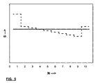
- Figure 5 is a figurative representation of the highest possible tension S occurring in any above mentioned parts or trajectories passed during operation of the belt, plotted for each ring N of a ring set, here provided with 10 rings.
- Number 1 in the plot stands for the innermost ring of the set, whereas No. 10 stands for the outermost ring.
- a similar plot can be made up for any number of rings in a set.
- the broken line in figure 4 represents a commercially available belt provided with practically no play, i.e. with at least some play between the rings.
- the solid line represents the tension in each ring of a belt according to the present invention in which the play between the ring has, as expressed in technical terms, a nominal value of zero.
- an inner ring of any pair of rings of a set may have some play relative to the outer ring, or may be somewhat longer than the inner diameter of the outer ring.
- these states are denoted positive and negative play respectively.
- the notion nominal further includes that the average value of plays of a given number of pairs of rings is zero. In technical sense this zero value includes a certain margin. In the construction a favourable embodiment of the margin would be 0.00005 times the outer diameter of an inner ring of any pair of a set in each direction, i.e. plus or minus of said outer diameter.
Landscapes
- Engineering & Computer Science (AREA)
- General Engineering & Computer Science (AREA)
- Mechanical Engineering (AREA)
- Transmissions By Endless Flexible Members (AREA)
- Devices For Conveying Motion By Means Of Endless Flexible Members (AREA)
Priority Applications (1)
| Application Number | Priority Date | Filing Date | Title |
|---|---|---|---|
| EP03077623A EP1369619A3 (fr) | 1999-09-15 | 2000-09-14 | Courroie |
Applications Claiming Priority (4)
| Application Number | Priority Date | Filing Date | Title |
|---|---|---|---|
| EP99203013 | 1999-09-15 | ||
| EP99203013A EP1085235A1 (fr) | 1999-09-15 | 1999-09-15 | Courroie |
| EP00960672A EP1216366B1 (fr) | 1999-09-15 | 2000-09-14 | Courroie |
| EP03077623A EP1369619A3 (fr) | 1999-09-15 | 2000-09-14 | Courroie |
Related Parent Applications (1)
| Application Number | Title | Priority Date | Filing Date |
|---|---|---|---|
| EP00960672A Division EP1216366B1 (fr) | 1999-09-15 | 2000-09-14 | Courroie |
Publications (2)
| Publication Number | Publication Date |
|---|---|
| EP1369619A2 true EP1369619A2 (fr) | 2003-12-10 |
| EP1369619A3 EP1369619A3 (fr) | 2006-08-30 |
Family
ID=29433263
Family Applications (2)
| Application Number | Title | Priority Date | Filing Date |
|---|---|---|---|
| EP00960672A Expired - Lifetime EP1216366B1 (fr) | 1999-09-15 | 2000-09-14 | Courroie |
| EP03077623A Withdrawn EP1369619A3 (fr) | 1999-09-15 | 2000-09-14 | Courroie |
Family Applications Before (1)
| Application Number | Title | Priority Date | Filing Date |
|---|---|---|---|
| EP00960672A Expired - Lifetime EP1216366B1 (fr) | 1999-09-15 | 2000-09-14 | Courroie |
Country Status (5)
| Country | Link |
|---|---|
| US (2) | US6830525B1 (fr) |
| EP (2) | EP1216366B1 (fr) |
| JP (1) | JP2003532840A (fr) |
| DE (1) | DE60027446T2 (fr) |
| ES (1) | ES2261238T3 (fr) |
Cited By (1)
| Publication number | Priority date | Publication date | Assignee | Title |
|---|---|---|---|---|
| CN100451383C (zh) * | 2005-02-14 | 2009-01-14 | 本田技研工业株式会社 | 金属带 |
Families Citing this family (10)
| Publication number | Priority date | Publication date | Assignee | Title |
|---|---|---|---|---|
| TW549560U (en) * | 2002-11-18 | 2003-08-21 | Ind Tech Res Inst | Rotational positioning mechanism for separating brittle material |
| JP4981679B2 (ja) | 2004-11-17 | 2012-07-25 | ロベルト ボッシュ ゲゼルシャフト ミト ベシュレンクテル ハフツング | プッシュベルト並びにその製作方法 |
| JP4641319B2 (ja) * | 2008-05-12 | 2011-03-02 | ジヤトコ株式会社 | 無段変速機用ベルト |
| DE112009005389T5 (de) * | 2009-11-19 | 2012-09-13 | Toyota Jidosha Kabushiki Kaisha | Übertragungsriemen |
| NL1039559C2 (en) * | 2012-04-23 | 2013-10-28 | Bosch Gmbh Robert | Belt-and-pulley-type continuously variable transmission. |
| NL1039980C2 (en) * | 2012-12-28 | 2014-07-03 | Bosch Gmbh Robert | Transverse segment for a drive belt with a carrier ring and multiple transverse segments. |
| NL1041639B1 (en) * | 2015-12-22 | 2017-07-03 | Bosch Gmbh Robert | Transverse member for a drive belt for a continuously variable transmission. |
| NL1041657B1 (en) | 2015-12-30 | 2017-07-11 | Bosch Gmbh Robert | Method for assembling a set of nested steel flexible rings and a drive belt provided there with. |
| EP3358215A4 (fr) * | 2016-02-12 | 2018-12-05 | Aisin AW Co., Ltd. | Courroie de transmission |
| WO2018221714A1 (fr) * | 2017-06-02 | 2018-12-06 | アイシン・エィ・ダブリュ株式会社 | Élément de courroie de transmission et courroie de transmission |
Citations (4)
| Publication number | Priority date | Publication date | Assignee | Title |
|---|---|---|---|---|
| US3720113A (en) | 1971-04-06 | 1973-03-13 | Doorne H Van | Flexible continuous power transmission means |
| US4512753A (en) | 1983-03-14 | 1985-04-23 | Honda Giken Kogyo Kabushiki Kaisha | V-belt transmission apparatus |
| US4579549A (en) | 1982-07-23 | 1986-04-01 | Toyota Jidosha Kabushiki Kaisha | Continuously variable transmission means |
| JPH10169719A (ja) | 1996-12-12 | 1998-06-26 | Nissan Motor Co Ltd | 無段変速機用vベルト |
Family Cites Families (19)
| Publication number | Priority date | Publication date | Assignee | Title |
|---|---|---|---|---|
| JPS597950U (ja) * | 1982-07-09 | 1984-01-19 | トヨタ自動車株式会社 | 無段変速機用駆動ベルト |
| GB2139731B (en) * | 1983-03-14 | 1986-03-26 | Honda Motor Co Ltd | V-belt transmissions |
| JPS6117743A (ja) * | 1984-07-04 | 1986-01-25 | Toyota Motor Corp | 動力伝達用無端ベルト |
| JPS6228548A (ja) | 1985-07-27 | 1987-02-06 | Kobe Steel Ltd | 動力伝達用スチ−ルベルト |
| JPS6237535A (ja) * | 1985-08-09 | 1987-02-18 | Nhk Spring Co Ltd | 伝動用ベルト |
| JPS62118928A (ja) | 1985-11-19 | 1987-05-30 | Kobe Steel Ltd | 金属製多層無端ベルトの矯正方法 |
| JPS63281726A (ja) * | 1987-05-13 | 1988-11-18 | Kobe Steel Ltd | 無端環状金属バンドの組立方法並びに装置 |
| US4787961A (en) | 1987-12-23 | 1988-11-29 | Dayco Products, Inc. | Belt construction, tensile band set therefor and methods of making the same |
| JP3079624B2 (ja) | 1991-04-22 | 2000-08-21 | 日産自動車株式会社 | 伝動ベルト |
| JP3189716B2 (ja) * | 1996-12-12 | 2001-07-16 | 日産自動車株式会社 | 無段変速機用vベルト |
| JPH11101312A (ja) | 1997-09-30 | 1999-04-13 | Mitsuboshi Belting Ltd | 高負荷伝動ベルト |
| JP3186678B2 (ja) | 1997-12-10 | 2001-07-11 | 日産自動車株式会社 | ベルト式無段変速機用金属帯の製造方法 |
| JP3524766B2 (ja) * | 1998-06-08 | 2004-05-10 | 本田技研工業株式会社 | 金属vベルト |
| JP3611968B2 (ja) * | 1998-06-26 | 2005-01-19 | 本田技研工業株式会社 | 金属vベルトの厚さ設定方法 |
| JP3527418B2 (ja) * | 1998-08-31 | 2004-05-17 | 本田技研工業株式会社 | 金属vベルト |
| JP3554490B2 (ja) * | 1998-09-25 | 2004-08-18 | 本田技研工業株式会社 | 無段変速機用ベルト |
| JP2000193041A (ja) * | 1998-12-24 | 2000-07-14 | Honda Motor Co Ltd | 金属vベルト |
| JP2001153607A (ja) * | 1999-09-16 | 2001-06-08 | Toyota Motor Corp | 伝動ベルトのフープずれ量計測装置 |
| JP2003120758A (ja) * | 2001-10-19 | 2003-04-23 | Honda Motor Co Ltd | 無段変速機用ベルト |
-
2000
- 2000-09-14 EP EP00960672A patent/EP1216366B1/fr not_active Expired - Lifetime
- 2000-09-14 EP EP03077623A patent/EP1369619A3/fr not_active Withdrawn
- 2000-09-14 DE DE60027446T patent/DE60027446T2/de not_active Expired - Lifetime
- 2000-09-14 ES ES00960672T patent/ES2261238T3/es not_active Expired - Lifetime
- 2000-09-14 JP JP2001523539A patent/JP2003532840A/ja active Pending
- 2000-09-14 US US10/088,118 patent/US6830525B1/en not_active Expired - Fee Related
-
2004
- 2004-10-26 US US10/972,471 patent/US7066859B2/en not_active Expired - Fee Related
Patent Citations (4)
| Publication number | Priority date | Publication date | Assignee | Title |
|---|---|---|---|---|
| US3720113A (en) | 1971-04-06 | 1973-03-13 | Doorne H Van | Flexible continuous power transmission means |
| US4579549A (en) | 1982-07-23 | 1986-04-01 | Toyota Jidosha Kabushiki Kaisha | Continuously variable transmission means |
| US4512753A (en) | 1983-03-14 | 1985-04-23 | Honda Giken Kogyo Kabushiki Kaisha | V-belt transmission apparatus |
| JPH10169719A (ja) | 1996-12-12 | 1998-06-26 | Nissan Motor Co Ltd | 無段変速機用vベルト |
Cited By (1)
| Publication number | Priority date | Publication date | Assignee | Title |
|---|---|---|---|---|
| CN100451383C (zh) * | 2005-02-14 | 2009-01-14 | 本田技研工业株式会社 | 金属带 |
Also Published As
| Publication number | Publication date |
|---|---|
| ES2261238T3 (es) | 2006-11-16 |
| EP1216366A2 (fr) | 2002-06-26 |
| US6830525B1 (en) | 2004-12-14 |
| DE60027446T2 (de) | 2007-04-19 |
| US7066859B2 (en) | 2006-06-27 |
| US20050059519A1 (en) | 2005-03-17 |
| EP1216366B1 (fr) | 2006-04-19 |
| EP1369619A3 (fr) | 2006-08-30 |
| DE60027446D1 (de) | 2006-05-24 |
| JP2003532840A (ja) | 2003-11-05 |
Similar Documents
| Publication | Publication Date | Title |
|---|---|---|
| EP1219860B1 (fr) | Courroie de transmission | |
| US7937925B2 (en) | Plate-link chain | |
| US7066858B2 (en) | Belt | |
| KR100668587B1 (ko) | 연속 가변 변속기용 구동 벨트, 그 연속 밴드 및 연속밴드 제조 방법 | |
| US6830525B1 (en) | Belt | |
| EP1352182B1 (fr) | Courroie | |
| US6123637A (en) | Metal V-belt | |
| US4579547A (en) | V-belt | |
| EP1257749B8 (fr) | Courroie de transmission variable en continu a cannelures multiples et poulie | |
| US8672787B2 (en) | Drive belt | |
| EP2061978A1 (fr) | Élément transversal pour une courroie de transmission pour une transmission variable en continu | |
| EP1085235A1 (fr) | Courroie | |
| AU2001238605A1 (en) | Multi-ribbed CVT belt | |
| EP1748219B1 (fr) | Courroie de transmission | |
| US8057342B2 (en) | Plate-link chain for a motor vehicle drive system | |
| JP5044416B2 (ja) | 駆動ベルト | |
| US20020151399A1 (en) | Compression belt for CVT having a crowned strut edge wherein the radius is determined by the maximum allowable contact stress and is located so that the contact point remains close to the rocking radius of the struts | |
| WO2002053937A1 (fr) | Courroie | |
| JP2003120759A (ja) | 高負荷伝動用vベルト及びそれを用いたベルト伝動装置 |
Legal Events
| Date | Code | Title | Description |
|---|---|---|---|
| PUAI | Public reference made under article 153(3) epc to a published international application that has entered the european phase |
Free format text: ORIGINAL CODE: 0009012 |
|
| AC | Divisional application: reference to earlier application |
Ref document number: 1216366 Country of ref document: EP Kind code of ref document: P |
|
| AK | Designated contracting states |
Kind code of ref document: A2 Designated state(s): BE DE DK ES FR GB IT NL |
|
| PUAL | Search report despatched |
Free format text: ORIGINAL CODE: 0009013 |
|
| AK | Designated contracting states |
Kind code of ref document: A3 Designated state(s): BE DE DK ES FR GB IT NL |
|
| 17P | Request for examination filed |
Effective date: 20070228 |
|
| AKX | Designation fees paid |
Designated state(s): BE DE DK ES FR GB IT NL |
|
| 17Q | First examination report despatched |
Effective date: 20080408 |
|
| RAP1 | Party data changed (applicant data changed or rights of an application transferred) |
Owner name: BOSCH TRANSMISSION TECHNOLOGY B.V. |
|
| STAA | Information on the status of an ep patent application or granted ep patent |
Free format text: STATUS: THE APPLICATION HAS BEEN WITHDRAWN |
|
| 18W | Application withdrawn |
Effective date: 20151211 |