EP1370058A2 - Appareil d'impression d'images et procédé de contrôle d'impression d'images - Google Patents
Appareil d'impression d'images et procédé de contrôle d'impression d'images Download PDFInfo
- Publication number
- EP1370058A2 EP1370058A2 EP03012699A EP03012699A EP1370058A2 EP 1370058 A2 EP1370058 A2 EP 1370058A2 EP 03012699 A EP03012699 A EP 03012699A EP 03012699 A EP03012699 A EP 03012699A EP 1370058 A2 EP1370058 A2 EP 1370058A2
- Authority
- EP
- European Patent Office
- Prior art keywords
- image data
- compressed image
- data
- memory
- stored
- Prior art date
- Legal status (The legal status is an assumption and is not a legal conclusion. Google has not performed a legal analysis and makes no representation as to the accuracy of the status listed.)
- Granted
Links
Images


Classifications
-
- G—PHYSICS
- G06—COMPUTING OR CALCULATING; COUNTING
- G06F—ELECTRIC DIGITAL DATA PROCESSING
- G06F3/00—Input arrangements for transferring data to be processed into a form capable of being handled by the computer; Output arrangements for transferring data from processing unit to output unit, e.g. interface arrangements
- G06F3/12—Digital output to print unit, e.g. line printer, chain printer
-
- H—ELECTRICITY
- H04—ELECTRIC COMMUNICATION TECHNIQUE
- H04N—PICTORIAL COMMUNICATION, e.g. TELEVISION
- H04N1/00—Scanning, transmission or reproduction of documents or the like, e.g. facsimile transmission; Details thereof
- H04N1/00127—Connection or combination of a still picture apparatus with another apparatus, e.g. for storage, processing or transmission of still picture signals or of information associated with a still picture
- H04N1/00278—Connection or combination of a still picture apparatus with another apparatus, e.g. for storage, processing or transmission of still picture signals or of information associated with a still picture with a printing apparatus, e.g. a laser beam printer
-
- H—ELECTRICITY
- H04—ELECTRIC COMMUNICATION TECHNIQUE
- H04N—PICTORIAL COMMUNICATION, e.g. TELEVISION
- H04N2201/00—Indexing scheme relating to scanning, transmission or reproduction of documents or the like, and to details thereof
- H04N2201/0008—Connection or combination of a still picture apparatus with another apparatus
- H04N2201/0015—Control of image communication with the connected apparatus, e.g. signalling capability
-
- H—ELECTRICITY
- H04—ELECTRIC COMMUNICATION TECHNIQUE
- H04N—PICTORIAL COMMUNICATION, e.g. TELEVISION
- H04N2201/00—Indexing scheme relating to scanning, transmission or reproduction of documents or the like, and to details thereof
- H04N2201/0008—Connection or combination of a still picture apparatus with another apparatus
- H04N2201/0034—Details of the connection, e.g. connector, interface
- H04N2201/0037—Topological details of the connection
- H04N2201/0041—Point to point
-
- H—ELECTRICITY
- H04—ELECTRIC COMMUNICATION TECHNIQUE
- H04N—PICTORIAL COMMUNICATION, e.g. TELEVISION
- H04N2201/00—Indexing scheme relating to scanning, transmission or reproduction of documents or the like, and to details thereof
- H04N2201/0008—Connection or combination of a still picture apparatus with another apparatus
- H04N2201/0034—Details of the connection, e.g. connector, interface
- H04N2201/0048—Type of connection
- H04N2201/0049—By wire, cable or the like
-
- H—ELECTRICITY
- H04—ELECTRIC COMMUNICATION TECHNIQUE
- H04N—PICTORIAL COMMUNICATION, e.g. TELEVISION
- H04N2201/00—Indexing scheme relating to scanning, transmission or reproduction of documents or the like, and to details thereof
- H04N2201/0077—Types of the still picture apparatus
- H04N2201/0084—Digital still camera
Definitions
- This invention relates to an image printing apparatus for printing input image data, which has been captured by, e.g., a digital camera, on a printing medium, and to a method of controlling such printing.
- Digital cameras capable of capturing an image and converting the captured image to digital data through a simple operation have become widespread in recent years.
- the general practice is to load the digital image data representing the captured image into a personal computer temporarily, subject the data to image processing in the personal computer and then output the processed image data to a color printer, which proceeds to print the image.
- a color printing system an image can be printed by sending the digital image data directly from a digital camera to a color printer without the intermediary of a personal computer.
- a PD printer a memory card that has been inserted into a digital camera and stores captured images is inserted directly into a color printer, which proceeds to print the captured images that have been stored on the memory card.
- Image data that has been stored in a digital camera generally is compressed according to the JPEG standard.
- the above-mentioned PD printer accepts the compressed image data as an input, stores the data in a buffer and then prints the data upon expanding it.
- means for achieving expansion in a case where compressed image data is input and then expanded and printed see the specification of Japanese Patent Application Laid-Open No. 10-262249 "Method and Apparatus for Expanding Compressed Image Data", by way of example.
- image data is extracted in MCUs (Minimum Coded Units) in an order other than that in which the data was stored as compressed image data.
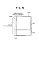
- Fig. 11 is a diagram illustrating the area (hatched portion) of an image memory in which image data exists in a case where JPEG data compressed in the order of raster scanning has been received in this order and expanded into an image.
- image data that has been expanded into an image is such that length in the horizontal direction differs for each image.
- the memory capacity of the image memory is set to be less than the capacity that is capable of storing all of the image data.
- the portion indicated at numeral 10000 is assumed to be the area in which data is capable of being stored in the image memory.
- the portion indicated at 11001 fits in the memory capacity of the image memory but the portion indicated at 11002 extends beyond this capacity and will not be stored. Since the scanning direction of the carriage (printhead) is vertical, the data portion indicated at 11004 within the data portion (the hatched portion: 11003 + 11004) printed by the initial scan of the printhead will not have been stored in the image memory. Owing to such print scanning, it becomes necessary to request the digital camera for the JPEG data that corresponds to the portion 11004 and to expand the image by acquiring and decoding this JPEG data. Such processing lengthens the time needed to print image data and results in an apparatus that is very difficult for the user to use.
- a feature of the present invention is to efficiently acquire and store image data, which is obtained from an image sensing device, in a memory and shorten the time needed to print the image by reducing the number of times image data is transferred from the image sensing device.
- a further feature of the present invention is to store image data efficiently and reduce the number of times image data is transferred, even in the case of a small-capacity memory, thereby making it possible to reduce the time needed to print the image.
- Fig. 1 depicts a perspective view of a PD printer 1000 according to this embodiment of the present invention.
- the PD printer 1000 functions as an ordinary personal-computer printer for receiving and printing data from a host computer (personal computer), and as a printer for directly reading and printing image data that has been stored on a storage medium such as a memory card or for receiving and printing image data from a digital camera.
- the main body constituting the shell of the PD printer 1000 of this embodiment has a lower case 1001, an upper case 1002, an access cover 1003 and a discharge tray 1004.
- the lower case 1001 forms the approximate lower half of the PD printer 1000 and the upper case 1002 the approximate upper half.
- a hollow structure having a storage space for internally accommodating mechanisms described later is constructed by combining the upper and lower cases, and the top and front sides of the structure are formed to have respective openings.
- the discharge tray 1004 has one edge thereof retained pivotally on the lower case 1001 and is so adapted as to open and close the opening, which has been formed in the front side of the lower case 1001, by being rotated forward and backward.
- the discharge tray 1004 When a printing operation is performed, therefore, the discharge tray 1004 is rotated forward to open the front opening, thereby making it possible to eject printed sheets from this opening and to successively stack the printed sheets. Further, the discharge tray 1004 accommodates two auxiliary trays 1004a and 1004b. When necessary, each tray can be pulled forward so that the paper supporting area can be increased or decreased in three stages.
- the access cover 1003 has one edge thereof pivotally retained on the upper case 1002 so as to be capable of opening and closing the opening formed in the top of the printer main body. Opening the access cover 1003 makes it possible to replace a printhead cartridge (not shown) or ink tank (not shown) accommodated within the main body. Though not particularly shown, opening the access cover 1003 causes a projection formed on the inner side thereof to turn a cover open/close lever. By detected the level rotation position by a microswitch or the like, the open/closed state of the access cover can be sensed.
- the top side of the upper cover 1002 is provided with a power key 1005.
- a control panel 1010 having a liquid crystal display 1006 and various key switches is provided on the right side of the upper cover 1002.
- the structure of the control panel 1010 will be described in detail later with reference to Fig. 2.
- An automatic feeder 1007 feeds printing sheets into the main body of the printer automatically.
- a paper selection level 1008 is a lever for adjusting the clearance between the printhead and printing sheets.
- a card slot 1009 receives an inserted adapter that is for loading and unloading a memory card. Image data that has been stored on the memory card can be directly loaded and printed via this adapter.
- a compact flash memory, smart media and memory stick, etc., are examples of the memory card.
- a viewer (liquid crystal display) 1011 is capable of being removably attached to the main body of the PD printer 1000.
- the viewer 1011 is used to display images frame by frame or index images as in a case where images desired to be printed are searched from images that have been stored on the memory card.
- a USB terminal 1012 is for connecting a digital camera, described later.
- the back side of the PD printer 1000 is provided with a USB connector for connecting a personal computer (PC).
- Fig. 2 depicts an external view of the control panel 1010 on the PD printer 1000 according to this embodiment.
- the liquid crystal display 1006 displays menu items for setting various data relating to items being printed. Items displayed include a starting photograph number and designated frame number of a range desired to be printed (start command designation print frame designation); final photograph number of the range for which printing has been completed (end); number of copies to be printed (number of copies); type of paper (printing sheet) used in printing (paper type); set number of photographs to be printing on one sheet of paper (layout); designation of printing quality (quality); designation as to whether date of photography is to be printed out (print date); designation as to whether a photograph is to be printed upon application of a correction (correct image); and display of number of sheets of paper used in printing (number of sheets). These items are selected or specified using a cursor key 2001.
- a mode key 2002 Whenever a mode key 2002 is pressed, printing type (index printing, printing of all frames, printing of a single frame, etc.) is changed over and a corresponding LED of LEDs 2003 is lit accordingly.
- a maintenance key 2004 is for performing printer maintenance, such as cleaning of the printhead and maintenance of the printer.
- a print start key 2005 is pressed when start of printing is specified or when setting up maintenance.
- a print stop key 2006 is pressed when printing is stopped and when halting of maintenance is specified.
- Fig. 3 illustrates a controller (control board) 3000.
- the controller 3000 includes an ASIC (a special-purpose customized LSI chip) the structure of which will be described later with reference to the block diagram of Fig. 4.
- a DSP (digital signal processor) 3002 has an internal CPU for executing various control processing, described later, and image processing such as conversion of a luminance signal (RGB) to a density signal (CMYK), smoothing, gamma conversion and error diffusion, etc.
- a memory 3003 has a program memory 3003a for storing the control program of the CPU in the DSP 3002, and a memory area that functions as a RAM area for storing a program at the time of execution and a work area for storing image data.
- a printer engine 3004 is that of an inkjet printer for printing a color image using color inks of a plurality of colors.
- a USB connector 3005 serves as a port for connecting a digital still camera (DSC) 3012.
- a connector 3006 is for connecting the viewer 1001.
- the controller 3000 further includes a USB hub 3008.
- the USB hub 3008 allows the data from the personal computer 3010 to pass through as is and outputs this data to the printer engine 3004 via the USB 3021.
- the connected personal computer 3010 is capable of executing printing by exchanging data and signals directly with the printer engine 3004 (i.e., the personal computer 3010 functions as an ordinary personal computer).
- a power-supply connector 3009 inputs DC voltage, which has been converted from commercial AC, from a power supply 3019.
- the personal computer 3010 is an ordinary personal computer.
- Numerals 3011 and 3012 denote the aforementioned memory card and digital still camera, respectively.
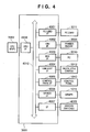
- Fig. 4 is a block diagram illustrating the structure of the ASIC 3100. Components in Fig. 4 identical with those shown in the foregoing drawings are designated by like reference characters and need not be described again.
- a memory-card interface 4001 reads image data that has been stored on an inserted memory card 3011 and writes data to the memory card 3011.
- An IEEE-1284-compliant interface 4002 is for exchanging data with the printer engine 3004.
- the IEEE-1284-compliant interface 4002 is a bus used in a case where image data that has been stored in the digital still camera 3012 or memory card 3011 is printed.
- USB interface 4003 for exchanging data with the personal computer 3010
- USB host interface 4004 for exchanging data with the digital still camera 3012
- control-panel interface 4005 for inputting various operating signals from the control panel 1010 and outputting display data to the liquid crystal display 1006
- viewer interface 4006 for controlling the display of data on the viewer 1011
- interface 4007 for controlling interfacing with various switches and LEDs 4009, etc.
- CPU interface 4008 for controlling the exchange of data with the DSP 3002.
- An internal bus (ASIC bus) 4010 interconnects the above-mentioned interfaces.
- Fig. 5 is a functional block diagram illustrating, in greater detail, the functional structure relating to image processing control in the PD printer 1000 according to this embodiment.
- Components in Fig. 5 identical with those shown in the foregoing drawings are designated by like reference characters and need not be described again.
- the JPEG decoder 7006 decodes the JPEG data at the time of printing and expands it into image data, at which time it repeatedly executes processing for requesting the input buffer 7000 for JPEG data to be decoded next in the raster order conforming to the order in which printing is performed, acquires the requested JPEG data, decodes the data and stores the decoded data in the RGB buffer 7001.
- An X, Y scaling unit 7010 converts the X- or Y-direction size of the image data that has been stored in the RGB buffer 7001.
- a 3D3 7007 converts the color space of the RGB data by referring to a look-up table 7009.
- a 3D6 7008 converts the RGB signal to a 6-color signal, namely C, M, Y, K, LC (light cyan) and LM (light magenta) signals, by referring to the look-up table 7009.
- a 1D output unit 7011 executes color processing such as a gamma conversion by referring to a one-dimensional table 7014.
- An error diffusion (ED) unit 7012 subjects multivalued image data to error diffusion processing, thereby generating binary image data (or multivalued data) for each color.
- the generated binary (or multivalued) image data is stored in an ED buffer 7003.
- a work buffer 7004 stores print data corresponding to each of a plurality of printheads that discharge ink of respective colors. The thus created print data corresponding to each of the printheads is sent to the printer engine 3004 via a printer interface 7103, whereby the image represented by the print data is printed.
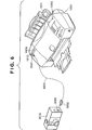
- Fig. 6 depicts a diagram useful in describing the connection between the PD printer 1000 and a digital still camera 3012 according to this embodiment.
- a cable 5000 has a connector 5001 that is connected to the USB terminal 1012 of the PD printer 1000 and a connector 5002 that is connected to a connection terminal 5003 on the digital still camera 3012. Further, the digital still camera 3012 is so adapted that image data being retained in an internal memory can be output via the connection terminal 5003. It should be noted that the digital still camera 3012 can be one having an internally provided memory as storage means or one equipped with a slot for loading a removable memory.
- the digital still camera 3012 has been connected to the PD printer 1000 as shown in Fig. 6, only a camera symbol is displayed on the display unit 1006 of the control panel 1010, the display on the control panel 1010 and the operation of the panel are rendered inoperative and so is the display on the viewer 1011. Accordingly, from this point onward, only operation of the keys on the digital still camera 3012 and display of images on the display unit (not shown) of the digital still camera 3012 are rendered effective. The user can therefore designate printing using the digital still camera 3012.
- Figs. 7A to 7C are diagrams useful in describing the structure of a memory area for storing image data contained in the input buffer 7000 that receives and stores the JPEG data from the digital still camera 3012.
- the input buffer 7000 stores the received JPEG data.
- the JPEG image data corresponding to this request is supplied to the JPEG decoder 7006, where the data is decompressed.
- the JPEG image data thus decompressed is converted to RGB data and YMCK data corresponding to the print image, and the resulting data it output to the printer engine 3004 in sync with scanning of the printhead in the printer engine 3004, whereby the image represented by the image data is printed.
- Fig. 7A is a conceptual view illustrating the memory structure of the input buffer 7000.
- the memory is divided into a plurality of cells (blocks) and the JPEG data is stored on a per-cell basis.
- the hatched portion indicates cells (valid cells) in which valid JPEG data has been stored
- the white cells indicate cells (empty cells) in which valid JPEG data has not been stored.
- Fig. 7B is a diagram useful in describing the data structure of each cell.
- Fig. 7B data (512 bytes) 601, which is JPEG data, is stored in each cell.
- Position information 602 indicates where (the byte number) in the original image file (JPEG file), the data 601 (which has been stored in the DSC 3012 or memory card 3011) is situated.
- a validity flag 603 indicates whether data in a cell is valid (flag ON) or not.
- a pointer 604 to a next cell indicates the cell that succeeds this cell.
- a pointer 605 of a previous cell indicates the immediately preceding cell linked to this cell.
- Fig. 7C is a diagram useful in describing the relationship among cells.
- Cells are logically related and connected in ring form in the following order: header cell 700 ⁇ empty cell ⁇ valid cell [cell order: oldest (namely the cell in which data was stored first) ⁇ newest (namely the cell in which data was stored most recently] ⁇ header cell 700.
- valid cells are arrayed in order from oldest to newest. When there are no longer any empty cells, therefore, the oldest valid cell is changed to an empty cell and the newest acquired data can be stored in this empty cell. Further, an empty cell is placed immediately following the header cell 700. When new compressed image data is received, therefore, an empty cell for storing this compressed image data can be found immediately.
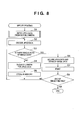
- This processing is started by specifying an image file and then specifying the printing thereof in the DSC 3012.
- step S1 the JPEG data of the specified image file is input from the DSC 3012 and stored in a prescribed memory area of the input buffer 7000.
- the processing of step S1 will be described later with reference to the flowchart of Fig. 9.
- Step S1 is followed by step S2, at which the JPEG data is sent to the JPEG decoder 7006 and decompression of the JPEG data is specified.
- step S3 When compressed data that has been stored in the input buffer 7000 is decompressed, it is determined at step S3 whether print data (image data) equivalent to a single scan of the printhead of printer engine 3004 can be produced or not. If such print data can be produced, control proceeds to step S6, at which the JPEG data is decompressed to develop a single main scan's worth of image data. Control then proceeds to step S7, at which a single main scan of print processing is executed, and then to step S8, at which it is determined whether print processing of this image file has been completed or not. If processing has not been completed, control returns to step S2, at which processing for expanding the compressed data of the next main scan is executed.
- step S3 If it is found at step S3 that a single main scan's worth of print data (image data) cannot be generated, control proceeds to step S4. Here the DSC 3012 is requested for JPEG data. The compressed data sent in response to this request is received and stored in the input buffer 7000 at step S5. Control then proceeds to step S2, at which the compressed data is decoded. If image data printed in one main scan is generated at step S3, control proceeds to print processing.
- Fig. 9 is a flowchart illustrating processing for inputting JPEG data from the DSC 3012 at step S1 in Fig. 8.
- step S11 the data in each cell (Fig. 7A) of the image data storage area of input buffer 7000 is initialized (cleared). Control then proceeds to step S12, at which the DSC 3012 is requested for JPEG data of the maximum size that can be acquired from the DSC 3012. This data is received. Next, at step S13, the received JPEG data is loaded into the input buffer 7000 cell by cell. This processing is executed repeatedly until it is confirmed at step S14 that empty cells no longer remain in the input buffer 7000.
- step S21 image data in an amount printed by the next main scan is supplied to the JPEG decoder 7006 and it is determined whether all of the JPEG data requested by the JPEG decoder 7006 has been processed. If all of the JPEG data has been processed, no further processing is necessary and processing is quit directly.
- step 522 it is determined whether the requested JPEG data has already been stored in any cell of the input buffer 7000. Specifically, since the JPEG data required next is specified by the JPEG decoder 7006, the data of the cell corresponding to this is found by referring to the position information 602 of this cell. When JPEG data thus requested has been stored in a cell, control proceeds to step S23. Here the JPEG data is read out of this cell and supplied to the JPEG decoder 7006.
- step S24 at which the validity flag 603 of the cell from which the JPEG data has been read out is turned off to indicate the data has been used, thereby rendering this cell an empty cell.
- This empty cell is then positioned to immediately follow the header cell 700 shown in Fig. 7C. Specifically, the pointer 604 to the cell that follows the header cell 700 is made the starting position of this empty cell, the pointer 605 of the cell preceding this empty cell is made a value that designates the tail end of the header cell, and the pointer 604 to the cell that follows this empty cell is changed to the starting position of the previous empty cell or, if there is no other empty cell, to a value that designates the start of the oldest valid cell. It goes without saying that pointers 604, 605 of valid cells or empty cells before and after a cell that has been changed from a valid cell to an empty cell also are changed in a similar manner.
- JPEG data that has already been stored in the input buffer 7000 is decoded and expanded into an image and a cell in which this JPEG data has been stored can be released by this decoding.
- step S22 when it is determined at step S22 that the JPEG data requested by the JPEG decoder 7006 has not been stored in any cell of the input buffer 7000, control proceeds to step S25 and the DSC 3012 must be requested for JPEG data. Since requesting the DSC 3012 only for the amount of JPEG data requested by the JPEG decoder 7006 is not efficient, JPEG data equivalent to a further several cells (an optimum acquired number of cells) is requested.
- a requisite condition is that the total value of (amount of JPEG data requested by JPEG decoder 7006) + (optimum acquired number of cells) be less than the amount of JPEG data (one packet's worth) that can be acquired at one time from the DSC 3012.
- step S26 When JPEG data transmitted from the DSC 3012 in accordance with requested amount of data is received, control proceeds to step S26, at which the JPEG data of the amount requested by the JPEG decoder 7006 is supplied to the JPEG decoder 7006. This is followed by step S27.
- step S27 In order to store the JPEG data requested superfluously from the DSC 3012 (namely the data of the optimum acquired number of cells) in the input buffer 7000, it is determined whether the input buffer 7000 has enough empty cells to store the JPEG data of the amount equivalent to the optimum acquired number of cells. If there are enough empty cells, control proceeds to step S28.
- the JPEG data of the amount equivalent to the optimum acquired number of cells is stored in the empty cells, the cells in which JPEG data has been stored anew are made valid cells and these cells are positioned to follow the newest valid cell (to precede the header cell 700) shown in Fig. 7C.
- step S29 If enough cells to store the JPEG data of the amount equivalent to the optimum acquired number of cells do not reside in the input buffer 7000, then control proceeds to step S29.
- the necessary number of cells [(number of optimum acquired cells)-(number of already existing empty cells)] from the oldest cell among the valid cells (namely the valid cell nearest to the header cell 700 logically speaking) are changed to empty cells.
- data for the JPEG data of the amount equivalent to the optimum acquired number of cells is reserved in consecutive empty cells in Fig. 7C.
- step S28 the JPEG data of the amount equivalent to the optimum acquired number of cells can be stored in the cells.
- the memory area of the input buffer (memory) 7000 is used efficiently so that the number of times JPEG data is acquired from DSC 3012 is reduced, thereby making it possible to shorten the time needed to acquire and print JPEG data from the DSC 3012.
- the present invention can be applied to a system constituted by a plurality of devices (e.g., a host computer, interface, reader, printer, etc.) or to an apparatus comprising a single device (e.g., a copier or facsimile machine, etc.).
- a host computer e.g., a host computer, interface, reader, printer, etc.
- an apparatus e.g., a copier or facsimile machine, etc.
- the object of the invention is attained also by supplying a storage medium (or recording medium) on which the program codes of the software for performing the functions of the foregoing embodiment (processing executed on the side of the camera and various print processing executed on the side of the printer) to a system or an apparatus have been recorded, reading the program codes with a computer (e.g., a CPU or MPU) of the system or apparatus from the storage medium, and then executing the program codes.
- a computer e.g., a CPU or MPU
- the program codes read from the storage medium themselves implement the novel functions of the embodiment, and the program codes per se and storage medium storing the program codes constitute the invention.
- the present invention covers a case where an operating system or the like running on the computer performs a part of or the entire process based upon the designation of program codes and implements the functions according to the embodiment.
- the present invention further covers a case where, after the program codes read from the storage medium are written in a function expansion card inserted into the computer or in a memory provided in a function expansion unit connected to the computer, a CPU or the like contained in the function expansion card or function expansion unit performs a part of or the entire process based upon the designation of program codes and implements the function of the above embodiment.
- a print-direct printer for receiving and printing JPEG data from a DSC divides the area of a memory into a plurality of blocks, stores the received JPEG data in the memory on a block-by-block basis and decompresses the compressed JPEG data that has been stored in the memory, thereby expanding the JPEG data into image data. If it is determined that JPEG data to be expanded next has not been stored in the memory, then the DSC is requested for JPEG data corresponding to at least one block, in an amount that is less than the maximum amount of data transferable from the DSC, in addition to the JPEG data to be expanded.
Landscapes
- Engineering & Computer Science (AREA)
- Multimedia (AREA)
- Signal Processing (AREA)
- Theoretical Computer Science (AREA)
- Human Computer Interaction (AREA)
- Physics & Mathematics (AREA)
- General Engineering & Computer Science (AREA)
- General Physics & Mathematics (AREA)
- Television Signal Processing For Recording (AREA)
- Record Information Processing For Printing (AREA)
- Compression Of Band Width Or Redundancy In Fax (AREA)
- Storing Facsimile Image Data (AREA)
Applications Claiming Priority (2)
| Application Number | Priority Date | Filing Date | Title |
|---|---|---|---|
| JP2002164623A JP4371632B2 (ja) | 2002-06-05 | 2002-06-05 | 画像記録装置及びその記録制御方法 |
| JP2002164623 | 2002-06-05 |
Publications (3)
| Publication Number | Publication Date |
|---|---|
| EP1370058A2 true EP1370058A2 (fr) | 2003-12-10 |
| EP1370058A3 EP1370058A3 (fr) | 2006-01-04 |
| EP1370058B1 EP1370058B1 (fr) | 2010-09-22 |
Family
ID=29545777
Family Applications (1)
| Application Number | Title | Priority Date | Filing Date |
|---|---|---|---|
| EP03012699A Expired - Lifetime EP1370058B1 (fr) | 2002-06-05 | 2003-06-04 | Appareil d'impression d'images et procédé de contrôle d'impression d'images |
Country Status (6)
| Country | Link |
|---|---|
| US (1) | US7274478B2 (fr) |
| EP (1) | EP1370058B1 (fr) |
| JP (1) | JP4371632B2 (fr) |
| KR (1) | KR100641257B1 (fr) |
| CN (1) | CN1222906C (fr) |
| DE (1) | DE60334264D1 (fr) |
Cited By (1)
| Publication number | Priority date | Publication date | Assignee | Title |
|---|---|---|---|---|
| EP1791340A2 (fr) * | 2005-10-07 | 2007-05-30 | Seiko Epson Corporation | Imprimante et dispositif de traitement d'image permettant d'imprimer des données brutes |
Families Citing this family (16)
| Publication number | Priority date | Publication date | Assignee | Title |
|---|---|---|---|---|
| US8605334B2 (en) * | 2002-08-05 | 2013-12-10 | Canon Kabushiki Kaisha | Recording system, recording apparatus, and control method therefor |
| JP2004135313A (ja) * | 2002-09-18 | 2004-04-30 | Canon Inc | 画像処理装置およびその方法 |
| JP2004165863A (ja) * | 2002-11-12 | 2004-06-10 | Murata Mach Ltd | カラー画像送信装置 |
| EP1452956A3 (fr) | 2003-02-12 | 2010-03-17 | Canon Kabushiki Kaisha | Système de commande d'impression |
| US7391913B2 (en) * | 2003-09-18 | 2008-06-24 | Arcsoft, Inc. | JPEG processing engine for low profile systems |
| WO2005109172A1 (fr) * | 2004-05-12 | 2005-11-17 | Samsung Electronics Co., Ltd. | Procede pour fournir des donnees multimedia pour impression directe, procede d'impression directe et appareil correspondant |
| EP1754136A4 (fr) * | 2004-05-12 | 2007-12-05 | Samsung Electronics Co Ltd | Procede et dispositif d'impression directe |
| US7411608B1 (en) * | 2004-08-20 | 2008-08-12 | Raymond Wayne Moskaluk | System and method for producing photographic prints |
| JP4367929B2 (ja) * | 2004-08-27 | 2009-11-18 | キヤノン株式会社 | 携帯電話及び印刷システムとその制御方法 |
| JP4902569B2 (ja) * | 2008-02-19 | 2012-03-21 | キヤノン株式会社 | 画像符号化装置及びその制御方法 |
| JP5121595B2 (ja) * | 2008-06-10 | 2013-01-16 | キヤノン株式会社 | 画像処理装置、画像処理装置の制御方法、記憶媒体及びプログラム |
| US9013750B2 (en) * | 2009-06-25 | 2015-04-21 | Canon Kabushiki Kaisha | Image processing for processing image data in correspondence with each pixel of an image |
| US8976411B2 (en) | 2009-07-01 | 2015-03-10 | Canon Kabushiki Kaisha | Image processing in correspondence with each pixel of an image |
| US8934134B2 (en) * | 2009-07-02 | 2015-01-13 | Canon Kabushiki Kaisha | Image processing based on pixel and attribute values |
| US9635218B2 (en) | 2009-07-03 | 2017-04-25 | Canon Kabushiki Kaisha | Image processing based on a pixel value in image data |
| US8411321B2 (en) * | 2009-09-09 | 2013-04-02 | Seiko Epson Corporation | Printing apparatus, layout adjustment method, program and recording medium |
Family Cites Families (15)
| Publication number | Priority date | Publication date | Assignee | Title |
|---|---|---|---|---|
| US5710931A (en) | 1994-09-07 | 1998-01-20 | Canon Kabushiki Kaisha | Suspension state control for information processing devices such as battery powered computers |
| JPH08123587A (ja) | 1994-10-27 | 1996-05-17 | Canon Inc | 携帯型情報処理装置 |
| JP3707170B2 (ja) | 1996-12-05 | 2005-10-19 | コニカミノルタビジネステクノロジーズ株式会社 | 画像形成装置 |
| EP0859326A3 (fr) | 1997-02-14 | 1999-05-12 | Canon Kabushiki Kaisha | Disposifif, système et méthode de transmission de données et dispositif de traitement d'images |
| US6195513B1 (en) * | 1997-02-17 | 2001-02-27 | Fuji Photo Film Co., Ltd. | Electronic camera accessory and image composition system |
| JP3559419B2 (ja) | 1997-03-18 | 2004-09-02 | 松下電器産業株式会社 | 画像圧縮データの伸張方法及び装置 |
| US5870535A (en) | 1997-05-12 | 1999-02-09 | Lexmark International, Inc. | Method and apparatus for building rasterized lines of bitmap data to be printed using a piecewise-linear direct memory access addressing mode of retrieving bitmap data line segments |
| JP3939825B2 (ja) | 1997-09-09 | 2007-07-04 | オリンパス株式会社 | 電子カメラ |
| US6356357B1 (en) | 1998-06-30 | 2002-03-12 | Flashpoint Technology, Inc. | Method and system for a multi-tasking printer capable of printing and processing image data |
| DE60009649T2 (de) | 1999-12-29 | 2005-03-24 | Hewlett-Packard Co. (N.D.Ges.D.Staates Delaware), Palo Alto | Verfahren und System zum Empfangen von Eingabe-Bild-Daten |
| JP4035278B2 (ja) | 2000-07-14 | 2008-01-16 | キヤノン株式会社 | 画像処理方法、装置および記録媒体 |
| JP2002125116A (ja) | 2000-10-17 | 2002-04-26 | Fuji Xerox Co Ltd | 画像処理装置 |
| JP2002262124A (ja) | 2000-11-30 | 2002-09-13 | Canon Inc | 画像処理装置及び方法と記録制御方法及び装置とプリンタドライバ |
| JP2002254611A (ja) | 2001-02-28 | 2002-09-11 | Canon Inc | 記録装置及び記録ヘッド特性データ選択方法 |
| US7130073B2 (en) * | 2002-05-10 | 2006-10-31 | Texas Instruments Incorporated | Efficient storage and rendering of patterns in a printer |
-
2002
- 2002-06-05 JP JP2002164623A patent/JP4371632B2/ja not_active Expired - Fee Related
-
2003
- 2003-05-27 US US10/444,991 patent/US7274478B2/en not_active Expired - Fee Related
- 2003-06-04 DE DE60334264T patent/DE60334264D1/de not_active Expired - Lifetime
- 2003-06-04 EP EP03012699A patent/EP1370058B1/fr not_active Expired - Lifetime
- 2003-06-05 KR KR1020030036499A patent/KR100641257B1/ko not_active Expired - Fee Related
- 2003-06-05 CN CNB031411800A patent/CN1222906C/zh not_active Expired - Fee Related
Cited By (4)
| Publication number | Priority date | Publication date | Assignee | Title |
|---|---|---|---|---|
| EP1791340A2 (fr) * | 2005-10-07 | 2007-05-30 | Seiko Epson Corporation | Imprimante et dispositif de traitement d'image permettant d'imprimer des données brutes |
| US7796289B2 (en) | 2005-10-07 | 2010-09-14 | Seiko Epson Corporation | Printer and image processing apparatus |
| US8107113B2 (en) | 2005-10-07 | 2012-01-31 | Seiko Epson Corporation | Printer and image processing apparatus |
| US8373885B2 (en) | 2005-10-07 | 2013-02-12 | Seiko Epson Corporation | Printer and image processing apparatus |
Also Published As
| Publication number | Publication date |
|---|---|
| JP2004009440A (ja) | 2004-01-15 |
| EP1370058B1 (fr) | 2010-09-22 |
| JP4371632B2 (ja) | 2009-11-25 |
| KR100641257B1 (ko) | 2006-11-03 |
| CN1471045A (zh) | 2004-01-28 |
| DE60334264D1 (de) | 2010-11-04 |
| KR20030094127A (ko) | 2003-12-11 |
| EP1370058A3 (fr) | 2006-01-04 |
| US7274478B2 (en) | 2007-09-25 |
| US20030227648A1 (en) | 2003-12-11 |
| CN1222906C (zh) | 2005-10-12 |
Similar Documents
| Publication | Publication Date | Title |
|---|---|---|
| KR100667119B1 (ko) | 기록 장치 및 그 제어 방법, 및 기록 매체 | |
| EP1370058B1 (fr) | Appareil d'impression d'images et procédé de contrôle d'impression d'images | |
| US7430054B2 (en) | Printing apparatus, control method therefor, and storage medium | |
| JP2003244630A (ja) | 画像処置装置、画像処理方法及びデジタルカメラ | |
| US7277198B2 (en) | Image printing apparatus, image printing system and control method | |
| CA2406351C (fr) | Imprimante, methode de commande d'imprimante et support de stockage | |
| JP4574282B2 (ja) | 画像供給デバイス及び該デバイスの制御方法及び印刷システムと印刷制御方法 | |
| JP4468120B2 (ja) | 画像供給デバイス及び該デバイスの制御方法とそのプログラムと記憶媒体 | |
| JP4047147B2 (ja) | 記録装置およびその制御方法 | |
| JP4612822B2 (ja) | 画像供給デバイス及び該デバイスの制御方法及び印刷システム | |
| JP4709246B2 (ja) | 画像供給デバイス及び該デバイスの制御方法及び印刷システム | |
| JP2003200621A (ja) | 記録装置及びその制御方法及び記録媒体 | |
| JP2003182165A (ja) | 印刷装置及びその制御方法 | |
| JP2007004715A (ja) | 画像供給デバイス及び該デバイスの制御方法及び印刷システム |
Legal Events
| Date | Code | Title | Description |
|---|---|---|---|
| PUAI | Public reference made under article 153(3) epc to a published international application that has entered the european phase |
Free format text: ORIGINAL CODE: 0009012 |
|
| AK | Designated contracting states |
Kind code of ref document: A2 Designated state(s): AT BE BG CH CY CZ DE DK EE ES FI FR GB GR HU IE IT LI LU MC NL PT RO SE SI SK TR |
|
| AX | Request for extension of the european patent |
Extension state: AL LT LV MK |
|
| PUAL | Search report despatched |
Free format text: ORIGINAL CODE: 0009013 |
|
| AK | Designated contracting states |
Kind code of ref document: A3 Designated state(s): AT BE BG CH CY CZ DE DK EE ES FI FR GB GR HU IE IT LI LU MC NL PT RO SE SI SK TR |
|
| AX | Request for extension of the european patent |
Extension state: AL LT LV MK |
|
| 17P | Request for examination filed |
Effective date: 20060704 |
|
| AKX | Designation fees paid |
Designated state(s): DE FR GB IT |
|
| 17Q | First examination report despatched |
Effective date: 20060829 |
|
| GRAP | Despatch of communication of intention to grant a patent |
Free format text: ORIGINAL CODE: EPIDOSNIGR1 |
|
| GRAS | Grant fee paid |
Free format text: ORIGINAL CODE: EPIDOSNIGR3 |
|
| GRAL | Information related to payment of fee for publishing/printing deleted |
Free format text: ORIGINAL CODE: EPIDOSDIGR3 |
|
| GRAS | Grant fee paid |
Free format text: ORIGINAL CODE: EPIDOSNIGR3 |
|
| GRAA | (expected) grant |
Free format text: ORIGINAL CODE: 0009210 |
|
| AK | Designated contracting states |
Kind code of ref document: B1 Designated state(s): DE FR GB IT |
|
| REG | Reference to a national code |
Ref country code: GB Ref legal event code: FG4D |
|
| REF | Corresponds to: |
Ref document number: 60334264 Country of ref document: DE Date of ref document: 20101104 Kind code of ref document: P |
|
| PG25 | Lapsed in a contracting state [announced via postgrant information from national office to epo] |
Ref country code: IT Free format text: LAPSE BECAUSE OF FAILURE TO SUBMIT A TRANSLATION OF THE DESCRIPTION OR TO PAY THE FEE WITHIN THE PRESCRIBED TIME-LIMIT Effective date: 20100922 |
|
| PLBE | No opposition filed within time limit |
Free format text: ORIGINAL CODE: 0009261 |
|
| STAA | Information on the status of an ep patent application or granted ep patent |
Free format text: STATUS: NO OPPOSITION FILED WITHIN TIME LIMIT |
|
| 26N | No opposition filed |
Effective date: 20110623 |
|
| REG | Reference to a national code |
Ref country code: DE Ref legal event code: R097 Ref document number: 60334264 Country of ref document: DE Effective date: 20110623 |
|
| PGFP | Annual fee paid to national office [announced via postgrant information from national office to epo] |
Ref country code: GB Payment date: 20140610 Year of fee payment: 12 |
|
| PGFP | Annual fee paid to national office [announced via postgrant information from national office to epo] |
Ref country code: DE Payment date: 20140630 Year of fee payment: 12 |
|
| PGFP | Annual fee paid to national office [announced via postgrant information from national office to epo] |
Ref country code: FR Payment date: 20140625 Year of fee payment: 12 |
|
| REG | Reference to a national code |
Ref country code: DE Ref legal event code: R119 Ref document number: 60334264 Country of ref document: DE |
|
| GBPC | Gb: european patent ceased through non-payment of renewal fee |
Effective date: 20150604 |
|
| REG | Reference to a national code |
Ref country code: FR Ref legal event code: ST Effective date: 20160229 |
|
| PG25 | Lapsed in a contracting state [announced via postgrant information from national office to epo] |
Ref country code: DE Free format text: LAPSE BECAUSE OF NON-PAYMENT OF DUE FEES Effective date: 20160101 Ref country code: GB Free format text: LAPSE BECAUSE OF NON-PAYMENT OF DUE FEES Effective date: 20150604 |
|
| PG25 | Lapsed in a contracting state [announced via postgrant information from national office to epo] |
Ref country code: FR Free format text: LAPSE BECAUSE OF NON-PAYMENT OF DUE FEES Effective date: 20150630 |