EP1370064B1 - Appareil de traitement d'image - Google Patents
Appareil de traitement d'image Download PDFInfo
- Publication number
- EP1370064B1 EP1370064B1 EP02705210A EP02705210A EP1370064B1 EP 1370064 B1 EP1370064 B1 EP 1370064B1 EP 02705210 A EP02705210 A EP 02705210A EP 02705210 A EP02705210 A EP 02705210A EP 1370064 B1 EP1370064 B1 EP 1370064B1
- Authority
- EP
- European Patent Office
- Prior art keywords
- image
- image processing
- image data
- gamma correction
- processing
- Prior art date
- Legal status (The legal status is an assumption and is not a legal conclusion. Google has not performed a legal analysis and makes no representation as to the accuracy of the status listed.)
- Expired - Lifetime
Links
- 238000012545 processing Methods 0.000 title claims abstract description 423
- 238000012937 correction Methods 0.000 claims description 133
- 239000011159 matrix material Substances 0.000 claims description 66
- 238000006243 chemical reaction Methods 0.000 claims description 65
- 238000007639 printing Methods 0.000 claims description 40
- 238000004364 calculation method Methods 0.000 claims description 39
- 238000000034 method Methods 0.000 claims description 18
- 230000004044 response Effects 0.000 claims description 9
- 230000005540 biological transmission Effects 0.000 claims 1
- 238000004590 computer program Methods 0.000 claims 1
- 239000000976 ink Substances 0.000 description 15
- 230000007246 mechanism Effects 0.000 description 7
- 230000006870 function Effects 0.000 description 6
- 230000003287 optical effect Effects 0.000 description 5
- 230000008859 change Effects 0.000 description 4
- 239000003086 colorant Substances 0.000 description 4
- 230000003247 decreasing effect Effects 0.000 description 4
- 230000002349 favourable effect Effects 0.000 description 3
- 238000003702 image correction Methods 0.000 description 3
- 230000008569 process Effects 0.000 description 3
- 238000013468 resource allocation Methods 0.000 description 3
- 230000015572 biosynthetic process Effects 0.000 description 2
- 238000010276 construction Methods 0.000 description 2
- 238000013500 data storage Methods 0.000 description 2
- 230000001419 dependent effect Effects 0.000 description 2
- 230000000694 effects Effects 0.000 description 2
- 241001014642 Rasta Species 0.000 description 1
- 230000006835 compression Effects 0.000 description 1
- 238000007906 compression Methods 0.000 description 1
- 238000010586 diagram Methods 0.000 description 1
- 238000009792 diffusion process Methods 0.000 description 1
- 238000005516 engineering process Methods 0.000 description 1
- 238000003780 insertion Methods 0.000 description 1
- 230000037431 insertion Effects 0.000 description 1
- 239000004973 liquid crystal related substance Substances 0.000 description 1
- 230000002093 peripheral effect Effects 0.000 description 1
- 238000003672 processing method Methods 0.000 description 1
- 230000000750 progressive effect Effects 0.000 description 1
- 238000001454 recorded image Methods 0.000 description 1
- 230000000717 retained effect Effects 0.000 description 1
- 230000035945 sensitivity Effects 0.000 description 1
- 239000007921 spray Substances 0.000 description 1
Images




Classifications
-
- H—ELECTRICITY
- H04—ELECTRIC COMMUNICATION TECHNIQUE
- H04N—PICTORIAL COMMUNICATION, e.g. TELEVISION
- H04N1/00—Scanning, transmission or reproduction of documents or the like, e.g. facsimile transmission; Details thereof
- H04N1/00912—Arrangements for controlling a still picture apparatus or components thereof not otherwise provided for
- H04N1/00954—Scheduling operations or managing resources
-
- H—ELECTRICITY
- H04—ELECTRIC COMMUNICATION TECHNIQUE
- H04N—PICTORIAL COMMUNICATION, e.g. TELEVISION
- H04N1/00—Scanning, transmission or reproduction of documents or the like, e.g. facsimile transmission; Details thereof
- H04N1/00127—Connection or combination of a still picture apparatus with another apparatus, e.g. for storage, processing or transmission of still picture signals or of information associated with a still picture
- H04N1/00249—Connection or combination of a still picture apparatus with another apparatus, e.g. for storage, processing or transmission of still picture signals or of information associated with a still picture with a photographic apparatus, e.g. a photographic printer or a projector
-
- H—ELECTRICITY
- H04—ELECTRIC COMMUNICATION TECHNIQUE
- H04N—PICTORIAL COMMUNICATION, e.g. TELEVISION
- H04N1/00—Scanning, transmission or reproduction of documents or the like, e.g. facsimile transmission; Details thereof
- H04N1/21—Intermediate information storage
- H04N1/2166—Intermediate information storage for mass storage, e.g. in document filing systems
- H04N1/217—Interfaces allowing access to a single user
-
- H—ELECTRICITY
- H04—ELECTRIC COMMUNICATION TECHNIQUE
- H04N—PICTORIAL COMMUNICATION, e.g. TELEVISION
- H04N1/00—Scanning, transmission or reproduction of documents or the like, e.g. facsimile transmission; Details thereof
- H04N1/32—Circuits or arrangements for control or supervision between transmitter and receiver or between image input and image output device, e.g. between a still-image camera and its memory or between a still-image camera and a printer device
- H04N1/32358—Circuits or arrangements for control or supervision between transmitter and receiver or between image input and image output device, e.g. between a still-image camera and its memory or between a still-image camera and a printer device using picture signal storage, e.g. at transmitter
-
- H—ELECTRICITY
- H04—ELECTRIC COMMUNICATION TECHNIQUE
- H04N—PICTORIAL COMMUNICATION, e.g. TELEVISION
- H04N1/00—Scanning, transmission or reproduction of documents or the like, e.g. facsimile transmission; Details thereof
- H04N1/40—Picture signal circuits
Definitions
- the present invention relates to an image processing device, an image processing output device, and an image processing program for carrying out image processing on image data.
- the image quality for digital image data generated by a digital still camera (DSC), digital video camera (DVC), scanner or the like can be arbitrarily adjusted with image processing.
- DSC digital still camera
- DVC digital video camera
- gamma correction processing, as well as brightness, contrast, sharpness and other image quality correction processing may be arbitrarily or automatically carried out in image processing.
- digital image data have the characteristic that a plurality of image data can be distributed on one printing sheet and that the layout can be freely edited when distributing the plurality of image data.
- a gamma correction table used in gamma correction processing or an LUT used in image quality correction processing is generated, and a holding area must be secured for each image datum in a storage area of the storage device such as a RAM.
- Document EP-A-0 938 041 describes a printer controller and a print system, wherein a printer driver of a host computer sends as image data a command which includes full-color RGB raster data.
- a printer-control-only circuit formed in the form of a hardware circuit subjects the full-color RGB raster data received from the driver to color conversion, halftoning, and interlacing, thereby converting the RGB rasta data into binary CMYK raster data.
- the printer-control-only circuit generates a printer command including as image data the binary CMYK raster data.
- the printer performs printing operations on the basis of the binary CMYK raster data included in the printer command from the printer-control-only circuit.
- Software stored in the printer driver and the printer do not perform any color conversion, halftoning, and interlacing operations.
- the present invention was devised to solve the problems, and it is an object thereof to decrease the amount of memory resources required for image processing as well as to implement suitable image processing for each image datum.
- the image processing device of the present invention it is possible to decrease the amount of memory resources required for image processing and suitable image processing can be carried out for each image.
- the image data and the image processing control information may be stored in the same file, or they may be saved in separate files while retaining their association.
- the image processing device of the present invention may further be equipped with second storage unit for storing predetermined image processing control information used in the image processing, wherein:
- the gamma correction work area securing unit in the image processing device may also acquire different gamma numbers based on the image processing control information associated with each of the plurality of image data contained in one output job, decide the storage capacity to allocate as the gamma correction work area for each image file reflecting the different gamma number, and secure the gamma correction work area based on the determined storage capacity.
- the storage capacity to be allocated as the gamma correction work area is decided reflecting the different gamma number, so it is possible to efficiently use the memory resources as well as to maintain gradation reproducibility of the image data.
- the gamma correction work area securing unit in the image processing device may also detect the number of image data contained in the main scanning direction which is the movement direction of an output mechanism carrying out the output, decide on the storage capacity to allocate as the gamma correction work area for each image reflecting the detected number of image data, and secure the gamma correction work area based on the decided storage capacity.
- a storage capacity is decided for allocation as a gamma correction work area reflecting the number of image data contained in the main scanning direction of the output mechanism, and the resolution of the gamma correction table is changed, so it is possible to effectively use the memory resources as well as to realize gradation reproducibility of the image data in response to the number of image data.
- the output mechanism in the image processing device may be a print head for carrying out printing or an electron gun for carrying out display.
- the gamma correction processing unit in the image processing device may also change the number of gradations in the gamma correction table generated in response to the secured gamma correction area.
- the image processing device of the present invention may further comprise color space conversion work area securing unit to secure a color space conversion work area in the storage area in order to implement color space conversion processing on the acquired image data, color space conversion processing unit for deciding on a color space conversion matrix based on the acquired image processing control information, applying the decided color space conversion matrix to the image data to develop the obtained calculation results in the color space conversion work area, and carrying out color space conversion processing on the acquired image data, and color space conversion work area releasing unit to release the secured color space conversion work area when the color space conversion processing on the image data is complete.
- color space conversion work area securing unit to secure a color space conversion work area in the storage area in order to implement color space conversion processing on the acquired image data
- color space conversion processing unit for deciding on a color space conversion matrix based on the acquired image processing control information, applying the decided color space conversion matrix to the image data to develop the obtained calculation results in the color space conversion work area, and carrying out color space conversion processing on the acquired image data
- color space conversion work area releasing unit to release
- the image processing device may further comprise image quality adjustment work area securing unit for securing an image quality adjustment work area in the storage area in order to implement image quality adjustment processing on the acquired image data, image quality adjustment processing unit for generating an image adjustment table in the image quality adjustment work area based on the acquired image processing control information, and carrying out image quality adjustment processing on the acquired image data using the generated image quality adjustment table, and image quality adjustment work area releasing unit for releasing the secured image quality adjustment work area when the image quality adjustment processing of the image data is complete.
- image quality adjustment work area securing unit for securing an image quality adjustment work area in the storage area in order to implement image quality adjustment processing on the acquired image data
- image quality adjustment processing unit for generating an image adjustment table in the image quality adjustment work area based on the acquired image processing control information, and carrying out image quality adjustment processing on the acquired image data using the generated image quality adjustment table
- image quality adjustment work area releasing unit for releasing the secured image quality adjustment work area when the image quality adjustment processing of the image data is complete.
- the image processing device of the present invention may further comprise third storage unit for storing a predetermined gamma correction table, and the gamma correction processing unit can implement image processing using the predetermined gamma correction table if the gamma correction work area cannot be secured in the storage area.
- the gamma correction processing unit can implement image processing using the predetermined gamma correction table if the gamma correction work area cannot be secured in the storage area.
- the image processing device of the present invention may further comprise fourth storage unit for storing a predetermined color space conversion matrix, and the color space conversion processing unit can implement image processing using the predetermined color space conversion matrix if the color space conversion work area cannot be secured in the storage area.
- fourth storage unit for storing a predetermined color space conversion matrix
- the color space conversion processing unit can implement image processing using the predetermined color space conversion matrix if the color space conversion work area cannot be secured in the storage area.
- the image processing device of the present invention may further comprise a fifth storage unit for storing a predetermined image quality adjustment table, and the image quality adjustment processing unit can implement image processing using the predetermined image quality adjustment table if the image quality adjustment work area cannot be secured in the storage area.
- a fifth storage unit for storing a predetermined image quality adjustment table
- the image quality adjustment processing unit can implement image processing using the predetermined image quality adjustment table if the image quality adjustment work area cannot be secured in the storage area.
- the securing and releasing of the work area needed for image processing on one image in a storage area with a capacity smaller than the work area capacity needed for image processing of all the image data contained in one output job is controlled, and image processing is carried out on all of the image data contained in one output job, so it is possible to decrease the amount of memory resources needed for image processing as well as to implement suitable image processing for each image datum.
- the computer readable medium of the present invention operation effects similar to those of the image processing device according to the present invention can be obtained. Also, the computer readable medium of the present invention may be realized in a variety of aspects similar to the image processing device of the present invention.
- the output device of the present invention it is possible to decrease the amount of memory resources required for image processing, and suitable image processing may be carried out on each image to print it.
- FIG. 1 is an explanatory view showing one example of an image processing system to which the image processing device according to the present embodiments may be applied.
- FIG. 2 is a block view showing an outline configuration of a digital still camera capable of generating an image file (image data) for output by the image processing device according to the present embodiments.
- FIG. 3 is an explanatory view showing the outside of a stand-alone type color printer as an image processing device and a printing device in the present embodiments.
- FIG. 4 is an outline view showing the internal configuration of a color printer which may be applied to the present embodiments.
- FIG. 5 is a block view showing the internal structure of a control circuit for the color printer 20.
- An image processing system 10 comprises a digital still camera 12 as an input device for generating an image file, a personal computer PC which may function as an image processing device for carrying out image processing based on the image file generated by the digital still camera 12 and for outputting printing image data, and a color printer 20 functioning as an image processing device and a printing device.
- the stand-alone type printer not the personal computer PC, is used as the image processing device.
- a CRT display, LCD display or other such monitor 14, a projector or the like may be used as the output device.
- the personal computer PC is a computer of the type generally used, and is equipped with a CPU 150 for executing an image processing program according to the present invention, a RAM 151 for temporarily storing operation results, image data, etc., from the CPU 150, and a hardware disk drive (HDD) 152 storing an image processing program.
- the personal computer PC is equipped with a card slot 153 for loading a memory card MC and an input/output terminal 154 for connecting a connection cable from the digital still camera 12 or the like.
- the digital still camera 12 is for acquiring images by causing optical information to form an image in a digital device (a CCD or photomultiplier tube), and is equipped with an optical circuit 121 comprising a CCD or the like for collecting optical information as shown in FIG. 2, an image acquisition circuit 122 for controlling the optical circuit 121 and acquiring images, an image processing circuit 123 for processing acquired digital images, and a control circuit 124 equipped with a memory for controlling circuits.
- the digital still camera 12 saves acquired images as digital data to the memory card MC as a storage device.
- the save format of the image data in the digital still camera 12 is generally JPEG, but other save formats such as TIFF, GIF, BMP and RAW data may also be used.
- the digital still camera 12 is also equipped with a selection/decision button 126 for setting the filming mode, for which a plurality of image processing control parametric values are set beforehand, in response to filming conditions as well as individual image processing control parameters such as brightness, contrast, exposure adjustment quantity (exposure adjustment value) and white balance; and a liquid crystal display 127 for previewing filmed images and setting the filming mode and the like using the selection/decision button 126.
- a selection/decision button 126 for setting the filming mode, for which a plurality of image processing control parametric values are set beforehand, in response to filming conditions as well as individual image processing control parameters such as brightness, contrast, exposure adjustment quantity (exposure adjustment value) and white balance
- a liquid crystal display 127 for previewing filmed images and setting the filming mode and the like using the selection/decision button 126.
- the digital still camera 12 used in the present image processing system stores, in addition to image data GD, image processing control information GC for the image data as an image file GF in the memory card MC. More specifically, along with the image data GD at the time of filming, the image processing control information GC is automatically stored in the memory card MC as information automatically composing an image file GF.
- the image file GF generated by the digital still camera 12 is transmitted to the color printer 20 through, for example, a cable CV and the computer PC, or through the cable CV. Alternately, the image file is transmitted to the color printer 20 through a connection via the computer PC in which the memory card MC on which the digital still camera 12 stored the image file is inserted in the memory slot, or by a direct connection of the memory card MC to the printer 20. The description below will be made based on the case where the memory card MC is connected or directly so to the color printer 20.
- the configuration of the color printer 20 according to the present embodiments will be described with reference to FIG. 3.
- the color printer 20 is a stand-alone type not needing the personal computer PC during image processing or print processing, and is equipped with an operation panel 21 for setting the printing paper, print resolution, print layout and the automatic image quality adjustment; and a memory card slot 22 with the memory card MC loaded, and having an interface function for reading and writing the recorded image file GF.
- a speaker 23 for carrying out voice guidance for printing operations may also be provided.
- the color printer 20 is capable of outputting color images, for example, a jet ink type printer which sprays inks having the four colors of cyan (C), magenta (M), yellow (Y) and black (K) to form an image through the formation of a dot pattern.
- the color printer 20 may be an electrophotographic type which transfers/fixes color toner on a printing medium to form images.
- the color inks light cyan (LC), light magenta (LM), and dark yellow (DY) may be used.
- An ink jet type printer will be used as an example in the below description.
- the color printer 20 comprises a mechanism for driving print heads IH1 to IH4 mounted on a carriage 30 and expelling ink or forming dots; a mechanism for moving the carriage 30 back and forth in the axial direction of a platen 32 using a carriage motor 31; a mechanism for feeding a cut paper 40 for printer using a paper feed motor 33; and a control circuit 50.
- the mechanism for moving the carriage 30 back and forth in the axial direction of the platen 32 comprises a sliding shaft 34 for holding the carriage 33 provided parallel to the axis of the platen 32, a pulley 36 holding between itself and the carriage motor 31 an endless drive belt 35, and the like.
- the control circuit 50 appropriately controls the movement of the paper feed motor 33, the carriage motor 31, and the print heads IH1 to IH4 while exchanging signals with the operation panel 21 of the printer.
- An ink cartridge INC1 and an ink cartridge INC2 are loaded in the carriage 30.
- Black (K) ink is held in the ink cartridge INC1, and other inks, or more specifically, the three colors of ink cyan (C), magenta (M), and yellow (Y), are held in the ink cartridge INC2.
- light cyan (LC), light magenta (LM) and light yellow (LY) inks may also be used.
- a CPU 51 a PROM 52, a RAM 53, a peripheral device input/output portion (PIO) 54, a timer 55, a drive buffer 56, and the like are provided inside the control circuit 50.
- the personal computer PC, the operation panel 21, the memory card slot 22, the speaker 23, the carriage motor 31, the paper feed motor 33, and an encoder 37 are connected to the PIO 54.
- the drive buffer 56 is used as a buffer for supplying dot-formation ON/OFF signals to the print heads IH1 to IH4. These are mutually connected with a bus 57, making the mutual exchange of data possible.
- an oscillator 58 for outputting drive waveforms at a predetermined frequency, and a distribution output device 59 for distributing outputs from the oscillator 58 to the ink heads IH1 to IH4 for expelling ink with a predetermined timing are provided in the control circuit 50.
- the control circuit 50 outputs dot data to the driver buffer 56 using a predetermined timing while keeping in synch with movements of the paper feed motor 33 and the carriage motor 31.
- FIG. 6 is an explanatory view conceptually showing one example of an internal configuration of the image file that can be used in the present embodiments.
- the image file GF according to the present embodiments can have a file structure conforming, for example, to the image file format standards (Exit) for digital still cameras.
- the specifications of Exif files are established by the JEITA (Japan Electronics and Information Technology Industries Association).
- the image file GF comprises a JPEG image data storage area 111 for storing image data in a JPEG format, and appended information storage area 112 for storing various information relating to the stored JPEG image data.
- the filming data and time, exposure, shutter speed, white balance, exposure correction value, target color space and other image processing control information GC referred to when outputting a JPEG image are stored in the appended information storage area 112.
- Thumbnail image data for the JPEG image stored in the JPEG image data storage area 111 are also stored in a TIFF format in the appended information storage area 112 in addition to the image processing control information GC.
- tags are used to specify data in Exif formatted files, and each datum may be called by the tag name.
- Terms such as file construction, data construction and storage area in the present embodiments mean the file or data image in a state where the file, data or the like is stored in the storage device.
- the image processing control information GC is related to the image quality when the image data is generated (when filming occurs) by an image data generation device such as the digital still camera 12, and parameters relating to the exposure time, the ISO sensitivity, the aperture, the shutter speed and the focus distance which may be arbitrarily set by the user or automatically when filming, or image processing control parameters such as the exposure correction value, the white balance, the filming mode, and the target color space which may be arbitrarily set by the user may also be included.
- the image file GF may be generated by a digital video camera, scanner or other input device (image file generation device).
- FIG. 7 is an explanatory view showing the layout of image data, and the timing of the securing and release of memory resources.
- FIG. 8 is an explanatory view conceptually showing the processing flow of the securing and releasing of memory resources in a RAM.
- the color printer 20 can implement printing with a plurality of image file GFs (image data GC) laid out on one printing sheet as well as being able to implement image processing including gamma correction processing, large color space conversion processing, inverse gamma correction processing and automatic image quality adjustment processing on the image data GD based on the image processing control information GC.
- image processing is carried out on the six image data GD based on the respective image processing control information GC when six image data are laid out on one printing sheet, and the amount of memory resources needed for image processing thus increases.
- the amount of loaded memory is limited with a stand-alone type printer such as the color printer 20 according to the present embodiments, and the amount of memory resources that can be used in image processing is limited.
- the amount of memory resources needed for image processing on one image datum GD is not large, and this can be adequately accommodated for with the amount of memory resources loaded depending on the number of image files that is the target of the image processing.
- the CPU 51 secures memory resources (a work area and a storage area) for the image processing of an image datum 1 in the storage area of the RAM 151 (S1), and secures a work area for the image processing of an image datum 2 in the storage area of the RAM 53 (S2).
- the CPU 51 further secures a work area for the image processing of an image datum 3, the last datum lined up in the main scanning direction, in the storage area of the RAM 53 (S3), and releases the memory resources secured in S1 when the image processing of the image datum 1 is complete (S4).
- the CPU 51 redistributes the memory resources, and when the image processing of the image datum 2 is complete, releases the memory resources secured in S2 (S5).
- the CPU 51 redistributes the memory resources, and when the image processing of the image datum 3 is complete, releases the memory resources secured in S3 (S6).
- the CPU 51 implements the securing and release processing of memory resources for the image data 4 to 6 included in one print job (output job) in the same sequence as S1 to S6 and implements the relocation of the memory resources (S7 to S11), and at the end, all of the memory resources in the storage area of the RAM 53 are released (S12).
- an amount of memory resources corresponding to the three image data GD lined up in the main scanning direction may be used in image processing by the color printer 20 according to the present embodiments to implement image processing on the six image data GD contained in one printing job (output job).
- image processing control information GC for all the image data GD contained in one printing job with, at the most, the amount of memory resources corresponding to the number of image data GD lined up in the main scanning direction. Also, even if the amount of memory resources is limited, it is possible to use them effectively.
- FIG. 9 is a flow chart showing the processing routine for image processing in the color printer 20 according to the present embodiments.
- FIG. 10 is a flow chart showing the processing routine for setting up a gamma correction table in the color printer 20 according to the present embodiments.
- FIG. 11 is a flow chart showing the processing routine for memory resource allocation processing for a gamma correction table in the color printer 20 according to the present embodiments.
- FIG. 12 is an explanatory view showing the condition where the amount of allocation of memory resources for a gamma correction table changes according to the number of image data.
- FIG. 13 is a flow chart showing the processing routine for matrix set-up processing in the color printer 20 according to the present embodiments.
- FIG. 14 is a flow chart showing the processing routine for automatic image quality adjustment LUT set-up processing in the color printer 20 according to the present embodiments.
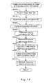
- FIG. 15 is a flow chart showing the processing routine for image processing based on the image processing control information GC in the color printer 20 according to the present embodiments.
- FIG. 16 is a flow chart showing the processing routine for regular image processing in the color printer 20 according to the present embodiments.
- FIG. 17 is a flow chart showing the processing routine for memory resource release processing in the color printer 20 according to the present embodiments.
- the image file GF generated by the digital still camera 12 is provided to the color printer 20 through a cable or through a memory card MC.
- the CPU 51 acquires layout information for the image file GF (image data GD) from the set printing conditions.
- the CPU 51 resets an image file counter GN to 0, and sets the number of GF image files GN ref contained on one printing sheet to based on the acquired layout information (step S100).
- the color printer 20 may be started up by detecting the insertion of the memory card MC into the card slot 22 or the connection of the digital still camera 12 to an input/output terminal 154 not illustrated through a cable.
- the CPU 51 reads the first image file GF from the memory card MC (step S110), temporarily stores the read image file GF in the RAM 53, and searches for the image processing control tag from the appended information storage area 112 for the image file GF (step S120). If the image processing control tag is found (step S130: Yes), the CPU 51 acquires the image processing control information GC written at the time the image data was generated and analyzes it (step S140). The CPU 51 sets up a gamma correction table, a color space conversion matrix and an automatic image quality adjustment LUT explained in detail below based on the analyzed image processing control information GC (step S150). The CPU 51 implements image processing based on the image processing control information GC using the set gamma correction table, color space conversion matrix and automatic image quality adjustment LUT (step S160).
- step S130 the CPU 51 cannot implement image processing reflecting the image processing control information GC from when the image data was generated, and the default gamma correction table, color space conversion matrix and automatic image quality adjustment LUT stored in the PROM 52 are set as the gamma correction table, color space conversion matrix and automatic image quality adjustment LUT used in regular image processing.
- the CPU 51 implements regular image processing using the set gamma correction table, color space conversion matrix and automatic image quality adjustment LUT based on the default values (step S180).
- the CPU 51 determines whether the gamma value of the camera has been set in the read image processing control information GC (step S200). If it is determined that the gamma value of the camera has been set (step S200: Yes), the CPU 51 implements processing to secure a area for a gamma correction table described below in the storage area of the RAM 53 (step S210). If it is determined that the area for the gamma correction table has been secured (step S220: Yes), the CPU 51 generates a correction table according to the below formulas using the gamma value set by the image processing control information GC.
- the CPU 51 sets a pointer indicating the offset position or the address stored in the generated gamma correction table (step S240).
- the CPU 51 sets a pointer indicating the default gamma correction table stored in the PROM 52 (step S250). Continuing, the CPU 51 implements set-up processing of a color space conversion matrix.
- the gamma correction processing for creating a gamma correction table in response to the number of gradations for the image data is a type of image processing requiring more memory resources than the matrix calculation processing or the automatic image quality adjustment LUT, and also affects the gradation of the image data GD.
- the allocation of memory resources for each image file GF can be said to be the allocation of memory resources for the gamma correction table.
- the image data has 8 bits (256) of gradation for each component, but it is possible to obtain favorable gradation printing effects by carrying out high precision calculations with more gradations in the internal calculations, so, for example, calculations with 16 bits (65536) of gradation or other such high gradations are carried out. If, however, a plurality of image data GD are contained in one printing job, the amount of memory resources allocated to the image processing of each image file GF (image data GD) is limited as already described.
- the amount of memory resources which can be used in the gamma correction table is limited to 100 KB when the amount of memory resources allocated to the matrix calculations and the automatic image quality adjustment LUT are taken into consideration, and it is necessary to implement gamma correction processing using a gamma correction table having a 14-bit gradation.
- the amount of memory resources needed is 65 (KB) even for a 16-bit gradation, so it is possible to implement gamma correction processing using a gamma correction table having a 16-bit gradation. In this manner, it is possible to printing results with a favorable gradation using a limited amount of memory resources by changing the gradation number in the gamma correction table in response to the number of image files GF contained in one print job.
- the CPU 51 acquires printing conditions from a printer driver (step S21 00). In concrete terms, layout information is acquired. The CPU 51 determines how many image files GF are lined up in the main scanning direction of one print sheet based on the acquired layout information, and sets the number of horizontal images HN (step S2110).
- the CPU 51 determines whether HN ⁇ 4 (step S2120), and if it is determined that HN ⁇ 4 (step S2120: No), it is determined whether HN ⁇ 2 (step S2130). If it is determined that HN ⁇ 2 (step S2130: No), the CPU 51 sets a 16-bit gradation as that for the gamma correction processing as shown in FIG. 12, and allocates 66 KB for a area WA ⁇ to create the gamma correction table. More specifically, the area secured for gamma correction processing is for generating the gamma correction table, and the gradation (resolution) of the gamma correction table is changed in response to the capacity of the allocated area.
- step S2120 determines whether HN ⁇ 4 (step S2120: Yes) or not. If it is determined that HN ⁇ 4 (step S2120: Yes), the CPU 51 sets a 14-bit gradation as that for gamma correction processing as shown in FIG. 12, and allocates 16 KB for the area WA ⁇ to create the gamma correction table. If it is determined that HN ⁇ 2 in the step S2130 (step S2130: Yes), the CPU 51 sets a 15-bit gradation for gamma correction processing as shown in FIG. 12, and allocates 33 KB for the area WA ⁇ to create the gamma correction table.
- the CPU 51 generates the gamma correction table with the set number of gradations (step S2150), and returns to the processing routine shown in FIG. 10.
- the amount of memory resources allocated to the gamma correction table is changed dynamically so the memory resources can be used effectively, and the number of gradations for the gamma correction table is changed according to the image size so the requirements for the image quality can be satisfied.
- the CPU 51 determines whether the color space is specified in the read image processing control information GC (step S300). If it is determined that the color space is specified (step S300: Yes), processing is carried out to secure a matrix calculation area in the storage area of the RAM 53 for developing the results of matrix calculations on the color values of the image data GD (step S310). When it is determined that the matrix calculation area is secured (step S320: Yes), the CPU 150 sets the color space conversion matrix based on the specified color space specified in the image processing control information GC. For example, if an NTSC color space is specified as the color space, the color space conversion matrix below will be used.
- the matrix calculation N -1 M is a combined matrix made from a matrix calculation M using a matrix M for converting RGB color space into XYZ color space, and a inverse matrix calculation N -1 of a matrix calculation N using a matrix N for converting wRGB color space into XYZ color space.
- the matrix M is not included in the display color area of sRGD color space, but is for maintaining effective image data (color values) as data, and converting the image data based on RGB color space to image data based on XYZ color space.
- the matrix values of the matrix M are determined according to the color space specified by the image processing control information GC.
- the inverse matrix N of the matrix N is for converting image data converted to image data based on XYZ color space by the matrix calculation M to wRGB color space having a area defined larger than sRGB color space (returning them to RGB color space).
- XYZ color space is one machine independent color space not dependent on the output properties of the machine, and is used for making correspondences for color values between RGB color space and wRGB color space.
- the color space of the obtained image data GD is wRGB color space having a area with a larger definition than sRGB color space.
- the color space used in image processing by a printer or computer is fixed at sRGB, but it was not possible to effectively use the color space of the digital still camera 12.
- the matrix (N -1 M) used in matrix calculation M corresponding to the color space information is changed, so the color space of the digital camera 12 is effectively used, and correct color reproduction is possible.
- the CPU 51 sets a pointer indicating the offset position or the memory address in the set matrix calculation area (step S340). If, however, it is determined that a color space is not specified in the image processing control information GC (step S300: No), and if it is determined that a matrix calculation area cannot be secured (step S320: No), the CPU 51 sets a pointer showing the default matrix calculation table stored in the PROM 52 (step S250). Continuing, the CPU 51 implements set-up processing for the image quality adjustment LUT.
- the set-up processing for the automatic image quality adjustment LUT which is one type of processing carried out in step S150, will be described with reference to FIG. 14.
- the CPU 51 determines whether image quality adjustment parameters are set in the read image processing control information GC (step S400). If it is determined that image quality adjustment parameters have been set (step S400: Yes), the CPU 51 implements processing to secure a area for an automatic image quality adjustment LUT in the storage area of the RAM 53 in order to generate an automatic image quality adjustment LUT based on the specified image quality adjustment parameters (step S410). If it is determined that the area for the automatic image quality adjustment LUT has been secured (step S420: Yes), the CPU 51 generates an automatic image quality adjustment LUT based on the image quality adjustment parameters specified by the image processing control information GC.
- the image data GD contained in the image file GF is analyzed, characteristic parametric values showing the image quality are acquired, and automatic adjustment of the image quality is carried out by correcting the image data, reflecting the image processing control information GC contained in the image file GF and the acquired characteristic parametric values.
- image quality automatic adjustment processing standard parameters which are correction targets are set beforehand, and differences between the standard parameters and the characteristic parameters of the image data GD are eliminated, or an image correction amount is determined such as to decrease the differences.
- the image processing control information GC may be used to change the standard parameter values, or may be used to change the degree to which the differences between the standard parameters and the characteristic parameters of the image data GD are decreased and the level of the application of the image correction amount.
- Image data correction is carried out for each pixel using a characteristic line associating the RGB signal input level and the output level, generally called a tone curve, for the brightness, contrast, color balance and the like, for example, with the image correction amount as the input level. Also, pixel calculation processing (filter processing), not tone curve processing, is carried out for each pixel for the color saturation, sharpness, noise decrease, and the like, for example.
- the CPU 51 sets a pointer indicating the offset position or the memory address stored by the generated automatic image quality adjustment LUT (step S440). If it is determined, however, that the image quality adjustment parameters have not been specified in the image processing control information GC (step S400: No), and it is determined that an automatic image quality adjustment LUT area cannot be secured (step S420: No), the CPU 51 sets a pointer indicating the default automatic image quality adjustment LUT stored in the PROM 52 (step S450). Continuing, the CPU 51 returns to the processing routine show in FIG. 9.
- the CPU 51 in the color printer 20 retrieves image data GD from the read image file GF (step S500).
- the read image data GD is not an original but a copy, and until the image processing is complete, a variety of image processing is carried out on the copy of the image data GD.
- the digital still camera 12 saves image data as a file with a JPEG format as already described, and the image data is saved in the JPEG file using YCbCr color space to increase the compression ratio.
- the CPU 51 implements a 3 x 3 matrix calculation S in order to convert the image data based on YCrCb color space to image data based on RGB color space (step S51 0).
- the matrix calculation S is the formula shown below.
- the CPU 51 implements gamma correction processing on image data based on RGB color space thus obtained (step S520).
- the CPU 51 specifies the gamma correction pointer set beforehand, and implements the gamma correction processing is carried out on the image data GD using the gamma correction table stored in the RAM 53.
- the CPU 51 implements the matrix calculation N -1 M on the image data GD, which has undergone gamma correction, using the matrix N -1 M already described in order to make correspondences between the original color space and wRGB color space (step S530).
- the CPU specifies the matrix calculation pointer in the RAM 53 set beforehand, and writes the results of the calculations on the image data GD to the specified area.
- the CPU 51 implements inverse gamma correction on the image data obtained from the matrix calculation N -1 M (step S50).
- the CPU 51 implements inverse gamma correction processing on the image data GD using the printer's default inverse gamma correction table stored in the PROM 52.
- the formula used to create the inverse gamma correction table is as below.
- the CPU 51 implements automatic adjustment processing for image quality on the image data GD which has undergone inverse gamma correction (step S550). To do so, the CPU 51 specifies the automatic image quality adjustment pointer set beforehand, and implements automatic image quality adjustment processing on the image data GD using the automatic image quality adjustment LUT stored in the RAM 53.
- the CPU 51 outputs the processed image data to the printer driver (step S560), implements memory resource release processing (step S570), and returns to the processing routine shown in FIG. 9.
- the memory resource release processing carried out in step 570 of the processing routine in FIG. 15 will be described with reference to FIG. 16.
- the CPU 51 determines whether a gamma correction table has been generated in the RAM 53 (step S5700). If it is determined that a gamma correction table has been generated in the RAM 53 (step S5700: Yes), the CPU 51 releases those memory resources allocated for the processed image data GD that comprise the gamma correction table (step S5710). If it is determined that a gamma correction table has not been generated in the RAM 53 (step S5700: No), the CPU 51 continues with the object processing in step S5720.
- the CPU 51 determines whether a matrix calculation area has been allocated in the RAM 53 (step S5720). If it is determined that a matrix calculation area has been allocated in the RAM 53 (step S5720: Yes), the CPU 51 releases those memory resources allocated for the processed image data GD which comprise the matrix calculation area (step S5730). If it is determined that a matrix calculation area has not been allocated in the RAM 53 (step S5720: No), the CPU 51 moves to the processing in step S5740.
- the CPU 51 determines whether an automatic image quality adjustment LUT has been generated in the RAM 53 (step S5740). If it is determined that an automatic image quality adjustment LUT has been generated in the RAM 53 (step S5740: Yes), the CPU. releases those memory resources allocated for the processed image data GD comprising the automatic image quality adjustment LUT (step S5750), and returns to the processing routine shown in FIG. 15. If it is determined that an automatic image quality adjustment LUT is not generated in the RAM 53 (step S5740: No), the CPU returns to the processing routine shown in FIG. 15.
- the CPU 51 of the color printer 20 retrieves image data GD from the read image file GF (step S600).
- the CPU 51 implements the 3 x 3 matrix calculation S in order to convert the image data based on YCrCb color space to image data based on RGB color space (step S610).
- the matrix calculation S is the formula already mentioned.
- the CPU 51 clips the image data obtained by the matrix calculation S and rounds it to values that are negative or else 256 or higher (for 8-bit gradation).
- the CPU 51 implements gamma correction processing on using the default gamma correction table (step S620), and implements color space conversion processing on the image data GD using the default color space conversion matrix table (step S630).
- the CPU 51 implements inverse gamma correction processing on the image data GD which has undergone color space conversion processing (step S640), implements automatic image quality adjustment processing on the image quality (step S650), outputs the image data GD which has undergone image processing to the printer driver (step S660), and returns to the processing routine shown in FIG. 9.
- the CPU 51 specifies the pointer set beforehand and acquires a table and LUT.
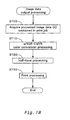
- Output processing or more specifically, print control processing carried out by the printer driver (print control program) on the image data GD will be described with reference to FIG. 18.
- the CPU 51 acquires image data contained in a print job (step S700), and implements wRGB-CMYK color conversion processing in order to print (step S71 0). Before the color conversion processing, it is fine to generate new data between neighboring image data using linear interpolation if the resolution of the image data GD is lower than the print resolution, and it is fine to implement resolution conversion processing to convert the resolution of the image data to the print resolution by carrying out pixel skipping on the data at a fixed ratio if, on the other hand, the resolution of the image data GD is higher than the print resolution.
- the results of the image processing on the copy of the image data GD thus far may be reflected in the original image data GD by opting to overwrite the image data.
- the CPU 51 changes the color space of the image data from wRGB color space to CMYK color space while referencing a conversion look-up table (LUT) associating the wRGB color space with the CMYK color space stored in the PROM 52. More specifically, the image data comprising R, G and B gradation values is converted to, for example, data having gradation values of the six colors C, M, Y, K, LC and LM used by the color printer 20.
- LUT conversion look-up table
- the CPU 51 implements the half-tone processing (step S720), implements the print processing (step S730), and ends the current processing routine.
- half-tone processing color-converted image data are received, and gradation number conversion processing is carried out.
- the image data after color conversion is realized as having a 256 gradation width for each color.
- the color printer 20 of the present embodiments can color only in a state of either "forming dots" or "not forming dots,” and the color printer 20 of the present embodiments can only render locally in 2 gradations. Image data having 256 gradations is thus converted to image data expressed in 2 gradations renderable by the color printer 20.
- Typical methods of this 2-gradation conversion (binarizing) processing are those referred to as the error diffusion method and the ordered dithering method.
- the CPU 51 implements interlace processing, reorganizing the image data converted to a format indicating the presence of dot formation into the sequence to be transmitted to the color printer 20.
- the amount of memory resources to be used for the image processing of each image file GF is decided with the maximum number of files laid out in the main scanning direction of the printing, the image processing is carried out with the decided amount of memory resources, and the memory resources are released after the image processing.
- the amount of memory resources required for image processing is decided with the maximum number of files laid out in the main scanning direction of the printing, the image processing is carried out with the decided amount of memory resources, and the memory resources are released after the image processing.
- the gradation number of the gamma correction table is decreased, varying the gradation number each time a gamma correction table, which requires the most memory resources, is created.
- a stand-alone type color printer 20 for carrying out image processing and print processing was used as an output device to implement image processing on image data GD; however, the present invention may be realized as an image processing device, and image processing may be carried out with the personal computer PC, a stand-alone type display device equipped with a display control circuit, or a portable terminal.
- the benefits of the present invention may be enjoyed where image processing is carried out on a plurality of image files by effectively using the memory resources.
- the present invention is useful for a portable terminal whose memory resources are limited.
- the output job is a display job whose image processing is carried out by the display control circuit.
- the image data is supplied to the display device through, for example, a network system, flash memory or other storage medium.
- the display device implements image processing in conjunction with the execution of gamma table generation processing and color conversion processing (matrix calculation processing and LUT processing) described in the present embodiments.
- gamma table generation processing and color conversion processing matrix calculation processing and LUT processing
- the amount of memory resources allocated for image processing exemplified in the present embodiments does not exceed exemplification used as convenience in the description; in the working of the invention, this may of course be modified arbitrarily according to the properties and use of the individual products.
- image processing may be carried out identical to that for all the image files in the so-called index printing and matrix printing modes. In these cases, the requirements on the quality of the image are ordinarily low because they are used to show which image files are included.
- memory resources were allocated for each image file, but the memory resources for the gamma correction table may be saved independently from the memory resources used for the matrix calculations and the like.
- different gamma values are acquired from the image files contained in one print job, and the memory resources for the gamma correction table can be allocated according to the number of different gamma values. More specifically, it is possible use the same gamma correction table for image files GF having the same gamma value, decreasing the memory resources.
- image processing is carried out, maintaining the minimum amount of memory resources with the premise of releasing the memory resources; however, for example, the number of image data contained in one output job can be detected, memory resources allocated beforehand in response to the number of image data detected without maintaining the minimum amount of memory resources, and image processing carried out within the range of the allocated memory resources. This is useful in cases such as when the resolution requirement for the output image is low. In such cases, it is not necessary to implement release processing for the memory resources.
- the values of the matrices S and N -1 M in various formulas are merely exemplifications, and it goes without saying that they may be arbitrarily modified according to the targeted color space or a color space, etc., available in the color printer 20.
- the embodiments were described using the digital still camera 12 as the image file generation device; however, scanners, digital video cameras and the like may also be used. If a scanner is used, the invention may be worked by the scanner alone, with the specification of the read data information for the image files GF carried out on the computer PC, or a preset button, display screen for arbitrary setting, or set-up button provided to allocate the preset information for the information set-up on the scanner.
- the embodiments were described using an a file having an Exif format as a concrete example of an image file GF, but the image file format according to the present invention is not limited thereto. In greater detail, it is fine as long as there are image data generated by the image data generation device, and an image file containing image processing control information GC mentioning the generation conditions (information) for the image data. With such a file, it is possible to output image quality for the image data generated with the image file generation device with suitable automatic adjustment.
- the embodiments were described using the case where the image data GD and the image processing control information GC are contained in the same image file GF as an example; however, the image data GD and image processing control information GC need not necessarily be stored in the same file.
- the image data and the image processing control information GC may be stored in separated files, and at the time of image processing when the image processing control information GC is used, the image data and the image processing control information GC have an absolutely unchangeable relationship, which substantially has the same function as when they are stored in the same file.
- a mode using an association between the image data and the image processing control information GC contains an image file GF in the present embodiments at least at the time of the image processing.
- image files stored on an optical disk medium such as a CD-ROM, CD-R, DVD-ROM or DVD-RAM are also included.
Landscapes
- Engineering & Computer Science (AREA)
- Multimedia (AREA)
- Signal Processing (AREA)
- General Engineering & Computer Science (AREA)
- Facsimile Image Signal Circuits (AREA)
- Image Processing (AREA)
- Record Information Processing For Printing (AREA)
- Image Input (AREA)
- Picture Signal Circuits (AREA)
- Dot-Matrix Printers And Others (AREA)
- Color, Gradation (AREA)
- Electrical Discharge Machining, Electrochemical Machining, And Combined Machining (AREA)
- Ultra Sonic Daignosis Equipment (AREA)
- Polarising Elements (AREA)
- Vehicle Body Suspensions (AREA)
- Eye Examination Apparatus (AREA)
- Fluid-Damping Devices (AREA)
Claims (24)
- Appareil de traitement des images destiné à effectuer un traitement des images à l'aide de données sur les images (GD) et d'informations sur la commande du traitement des images (GC) utilisées au cours du traitement des données des images sur les images et associées avec celles-ci pour sortir lesdites données sur les images à l'aide d'une imprimante, l'appareil de traitement des images comprenant :une première unité de mémoire (53) ayant une zone de mémoire avec une capacité prédéterminée utilisée dans le traitement des images ;une unité d'acquisition des données sur les images ((51)) destinée à acquérir des données sur les images (GD) d'une pluralité d'images contenues dans un travail de sortie destiné à imprimer sur un support d'impression, selon une séquence de sortie destinée à sortir des images ;une unité d'acquisition des informations ((51)) destinée à acquérir les informations sur la commande du traitement des images (GC) associées aux données sur les images acquises de chacune desdites images, respectivement ; caractérisée en ce queune unité de sécurisation de la zone travail (51) destinée à sécuriser une ou une pluralité de zones de travail dans la zone de mémoire nécessaire au traitement des images sur les données de chacune des images acquises d'une ou d'une pluralité d'images parmi lesdites images alignées dans la direction principale de balayage de l'imprimante, respectivement ;une unité de traitement des images (51) destinée à effectuer un traitement des images sur les données de chacune des images acquises desdites images alignées dans la direction principale de balayage basée sur les informations sur la commande du traitement des images acquises à l'aide des zones de travail sécurisées, respectivement ; etune unité de libération des zones de travail (51) destinée à libérer une zone de travail sécurisée respective parmi lesdites zones de travail sécurisées, lorsque le traitement des images sur les données des images d'une image correspondante desdites images est terminé.
- Appareil de traitement des images selon la revendication 1, comprenant en outre :une seconde unité de mémoire ((52)) destinée à la mémorisation des informations prédéterminées sur la commande du traitement des images utilisées dans le traitement des images, etdans lequel l'unité de traitement des images (51) met en oeuvre un traitement des images basé sur les informations prédéterminées sur la commande du traitement des images (GC) lorsque la zone de travail destinée à une image qui est une cible du traitement des images ne peut pas être sécurisée dans la zone de mémoire.
- Appareil de traitement des images selon l'une quelconque des revendications 1 à 2, comprenant en outre :une unité de sécurisation de la zone de travail de correction du gamma (51) destinée à sécuriser une zone de travail de correction du gamma dans la zone de mémoire destinée à effectuer un traitement de correction du gamma sur les données des images (GD) d'une image respective ; etune unité de traitement de correction du gamma (51) destinée à générer une table de correction du gamma dans la zone de travail de correction du gamma basée sur les informations sur la commande du traitement des images acquises (GC), et destinée à effectuer un traitement de correction du gamma des données sur les images (GD) de ladite image à l'aide de la table de correction du gamma générée.
- Appareil de traitement des images selon la revendication 3, caractérisé en ce que l'unité de sécurisation de la zone de travail de correction du gamma (51) acquiert différentes valeurs du gamma basées sur des informations sur la commande du traitement des images (GC) associées à des données sur les images (GD) d'une pluralité d'images contenues dans un travail de sortie, décidant de la capacité de mémoire à affecter comme zone de travail de correction du gamma destinée à chaque image reflétant une valeur différente du gamma, et sécurisant la zone de travail de correction du gamma basée sur la capacité de mémoire décidée.
- Appareil de traitement des images selon la revendication 3, caractérisé en ce que l'unité de sécurisation de l'espace de travail de correction du gamma détecte un certain nombre d'images contenues dans la direction principale de balayage de l'imprimante, décidant d'une capacité de mémoire à affecter comme zone de correction du gamma destinée à chaque image reflétant le nombre d'images détecté d'affecter comme zone de correction du gamma destinée à chaque image reflétant le nombre d'images détecté, et sécurisant la zone de travail de correction du gamma basée sur la capacité de mémoire décidée.
- Appareil de traitement des images selon l'une quelconque des revendications 4 à 5, dans lequel l'unité de traitement de correction du gamma (51) change un certain nombre de gradations destinées à la table de correction du gamma générée en réponse à la zone de correction du gamma sécurisée.
- Appareil de traitement des images selon la revendication 3, comprenant en outre :une unité de sécurisation de la zone de travail de conversion de l'espace couleurs (51) destinée à sécuriser une zone de travail de conversion de l'espace couleurs dans la zone de mémoire afin de mettre en oeuvre un traitement de conversion de l'espace couleurs sur les données des images (GD) de ladite image ;une unité de traitement par conversion de l'espace couleurs (51) destinée à décider d'une matrice de conversion de l'espace couleurs basée sur les informations sur la commande du traitement des images acquises (GC), en développant des résultats de calculs obtenus en appliquant la matrice de conversion de l'espace couleurs décidée aux données des images (GD) de ladite image à la zone de travail de conversion de l'espace couleurs et en effectuant ainsi le traitement de conversion de l'espace couleurs sur les données des images (D) de ladite image ; etune unité de libération de la zone de travail de conversion de l'espace couleurs (51) destinée à libérer la zone de travail de conversion de l'espace couleurs sécurisée lorsque le traitement par conversion de l'espace couleurs sur les données de l'image (GD) de ladite image est terminé.
- Appareil de traitement des images selon la revendication 3 ou 7, comprenant en outre :une unité de sécurisation de la zone de travail de réglage de la qualité de l'image (51) destinée à sécuriser la zone de travail de réglage de la qualité de l'image dans la zone de mémoire destinée à effectuer un traitement de réglage de la qualité de l'image sur les données des images (GD) de ladite image ;une unité de traitement de réglage de la qualité de l'image (51) destinée à générer une table de réglage de la qualité de l'image dans la zone de travail de réglage de la qualité de l'image basée sur les informations sur la commande du traitement des images acquises (GC), et effectuant un traitement de réglage de la qualité de l'image sur les données des images(GD) de ladite image à l'aide de la table de réglage de la qualité de l'image générée ; etune unité de libération de la zone de travail de réglage de la qualité de l'image (51) destinée à libérer la zone de travail de réglage de la qualité de l'image sécurisée lorsque le traitement du réglage de la qualité d'image sur les données des images de ladite image est terminé.
- Appareil de traitement des images selon la revendication 3, comprenant en outre :une troisième unité de mémoire ((52)) destinée à mémoriser une table prédéterminée de correction du gamma ; etdans lequel l'unité de traitement de correction du gamma (51) met en oeuvre un traitement des images à l'aide de la table prédéterminée de correction du gamma lorsque la zone de travail de correction du gamma ne peut pas être sécurisée dans la zone de mémoire.
- Appareil de traitement des images selon la revendication 7, comprenant en outre :une quatrième unité de mémoire (52) destinée à mémoriser une matrice de conversion prédéterminée de l'espace couleurs ; etdans lequel l'unité de traitement par conversion de l'espace couleurs (51) met en oeuvre le traitement des images à l'aide de la matrice de conversion prédéterminée de l'espace couleurs lorsque la zone de travail de conversion de l'espace couleurs ne peut pas être sécurisée dans la zone de mémoire.
- Appareil de traitement des images selon la revendication 8, comprenant en outre:une cinquième unité de mémoire (52) destinée à mémoriser une table prédéterminée de réglage de la qualité de l'image ; etdans lequel l'unité de traitement du réglage de la qualité de l'image met en oeuvre le traitement des images à l'aide de la table de réglage prédéterminé de la qualité de l'image lorsque la zone de travail de réglage de la qualité de l'image ne peut pas être sécurisée dans la zone de mémoire.
- Appareil de traitement des images selon l'une quelconque des revendications 1 à 11, comprenant en outre :une unité de détection du nombre de données des images (51) destinée à détecter un nombre maximum d'images contenues dans la direction principale de balayage de l'imprimante ;une unité de division de la zone de mémoire (51) destinée à diviser la zone de mémoire à partir du nombre d'images détecté ; dans laquelleladite unité d'acquisition d'informations est adaptée pour acquérir les informations sur la commande du traitement des images acquises associées à chacun des images le long de la direction principale de balayage ; etladite unité de traitement des images est adaptée pour effectuer un traitement des images basées sur les informations sur la commande du traitement des images acquises sur les données des images de chacune desdites images leur correspondant à l'aide de la zone de mémoire divisée.
- Appareil de traitement des images selon l'une quelconque des revendications 1 à 12, comprenant en outre :une unité de transmission des données des images destinée à transmettre des données des images ayant subi le traitement des images, dans laquelleladite première unité de mémoire présente une zone de mémoire d'une capacité inférieure à la capacité de la zone de travail normalement nécessaire au traitement des images sur toutes les données des images d'images contenues dans un travail de sortie; etladite unité de traitement des images est adaptée pour commander la sécurisation et la libération de ladite zone de travail dans la zone de mémoire nécessaire au traitement des images des données des images de ladite image, et pour effectuer le traitement des images sur toutes les données des images des images contenues dans un travail de sortie.
- Procédé de réalisation d'un traitement des images à l'aide de données des images (GD) et d'informations sur la commande du traitement des images (GC) utilisées au cours du traitement des images des données des images et associées à celles-ci destiné à la sortie desdites données des images à l'aide d'une imprimante, le procédé comprenant les étapes consistant à :acquérir des données des images d'une pluralité d'images contenues dans un travail de sortie pour impression sur un support d'impression, selon une séquence de sortie destinée à la sortie d'images ;acquérir les informations sur la commande du traitement des images associées aux données des images acquises de chacune desdites images, respectivement ; le procédé étant caractérisé parla sécurisation d'une ou d'une pluralité de zones de travail dans une zone de mémoire dans une première unité de mémoire ((53)), qui sont nécessaires au traitement d'images sur les données de chaque image acquise d'une ou d'une pluralité d'images parmi les dites images alignées dans la direction principale de balayage de l'imprimante, respectivement ;la réalisation d'un traitement des images sur les données de chaque image acquise desdites images alignées dans la direction principale de balayage basée sur les informations sur la commande du traitement des images acquises à l'aide des zones de travail sécurisées, respectivement ; etla libération d'une zone de travail respective sécurisée desdites zones de travail sécurisées, lorsque le traitement des images sur les données des images d'une image correspondante desdites images est terminé.
- Procédé selon la revendication 14, comprenant en outre :la sécurisation d'une zone de travail de correction du gamma dans ladite zone de mémoire afin de mettre en oeuvre un traitement de correction du gamma sur les données des images acquises d'une image respective ; etla génération d'une table de correction du gamma dans la zone de travail de correction du gamma à partir des informations sur la commande du traitement des images acquises (GC), et la réalisation d'un traitement de correction du gamma sur les données des images acquises de ladite image à l'aide de la table de correction du gamma générée.
- Procédé selon la revendication 15, dans lequel le procédé est caractérisé en ce que la sécurisation de la zone de travail de correction du gamma est réalisée en acquérant différentes valeurs du gamma à partir d'informations sur la commande du traitement des images (GC) associées à des données des images d'une pluralité d'images contenues dans un travail de sortie, en décidant de la capacité de mémoire à affecter comme zone de travail de correction du gamma destinée à chaque image reflétant les différentes valeurs du gamma, et sécurisant la zone de travail de correction du gamma à partir de la capacité de mémoire décidée.
- Procédé selon la revendication 15, dans lequel le procédé est caractérisé en ce que la sécurisation de la zone de correction du gamma est réalisée en détectant un nombre d'images contenues dans la direction principale de balayage de l'imprimante, en décidant de la capacité de mémoire à affecter comme zone de travail de correction du gamma destinée à chaque image reflétant le nombre d'images détecté, et en sécurisant la zone de travail de correction du gamma basée sur la capacité de mémoire décidée.
- Procédé selon la revendication 15, comprenant en outre:la sécurisation d'une zone de travail de conversion de l'espace couleurs dans la zone de mémoire afin de mettre en oeuvre le traitement par conversion de l'espace couleurs sur les données des images de ladite image ;la décision d'une matrice de conversion de l'espace couleurs à partir des informations sur la commande du traitement des images acquises, en développant des résultats de calcul obtenus en appliquant la matrice de conversion de l'espace couleurs décidé aux données des images de ladite image à la zone de conversion de l'espace couleurs et en effectuant ainsi un traitement par conversion de l'espace couleurs sur les données des images acquises de ladite image ; etla libération de la zone de travail de conversion de l'espace couleurs sécurisée lorsque le traitement par conversion de l'espace couleurs sur les données des images de ladite image est terminé.
- Procédé selon la revendication 15 ou 18, comprenant en outre :la sécurisation d'une zone de travail de réglage de la qualité de l'image dans la zone de mémoire afin de mettre en oeuvre un traitement de réglage de la qualité de l'image sur les données des images acquises de ladite image ;la génération d'une table de réglage de la qualité de l'image à partir des informations sur la commande du traitement des images acquises, et la réalisation d'un traitement par réglage de la qualité de l'image sur les données des images acquises de ladite image à l'aide de la table de réglage de la qualité de l'image générée ; etla libération de la zone de travail de réglage de la qualité de l'image sécurisée lorsque le traitement par réglage de la qualité de l'image sur les données des images de ladite image est terminé.
- Procédé selon l'une quelconque des revendications 14 à 19, comprenant en outre :la détection d'un nombre maximum d'images contenues dans la direction principale de balayage de l'imprimante ;la division de la zone de mémoire d'une unité de mémoire basée sur le nombre d'images détecté ;l'acquisition des informations sur la commande du traitement des images (GC) associées à chacune des images le long d'une direction principale de balayage ; etl'utilisation de la zone de mémoire divisée pour mettre en oeuvre le traitement des images sur les données des images (GD) des images à l'aide des informations sur la commande du traitement des images acquises (GC).
- Procédé selon l'une quelconque des revendications 14 à 20,
dans lequel ladite zone de travail nécessaire au traitement des images sur les données des images d'une image dans ladite zone de mémoire a une capacité inférieure à la capacité d'une zone de travail nécessaire au traitement des images sur toutes les données des images de toutes les images contenues dans un travail de sortie. - Appareil de sortie (20) destiné à sortir une image correspondant à un travail de sortie contenant une pluralité de données des images (GD) à l'aide d'informations sur la commande du traitement des images (GC) utilisées au cours du traitement des images des données des images (GD) et associées à celles-ci, l'appareil de sortie (20) comprenant :un appareil de traitement des images selon l'une quelconque des revendications 1 à 13 ; etune unité de sortie des données des images destinée à sortir des données des images (GD) ayant subi le traitement des images.
- Appareil de sortie (20) selon la revendication 22, dans lequel l'unité de sortie des données des images sort des données des images (GD) ayant subi le traitement des images pour chaque trame.
- Support informatique de lecture mémorisant un code de programme de traitement des images pour effectuer un traitement des images à l'aide de données des images (GD) et d'informations sur la commande du traitement des images (GC) utilisées au cours du traitement des images des données des images (GD) et associées à celles-ci, le support informatique de lecture comprenant :des codes des programmes informatiques respectifs destinés à la réalisation de toutes les étapes du procédé selon l'une quelconque des revendications 14 à 21.
Applications Claiming Priority (3)
| Application Number | Priority Date | Filing Date | Title |
|---|---|---|---|
| JP2001074568 | 2001-03-15 | ||
| JP2001074568 | 2001-03-15 | ||
| PCT/JP2002/002447 WO2002076085A1 (fr) | 2001-03-15 | 2002-03-14 | Appareil de traitement d'image |
Publications (3)
| Publication Number | Publication Date |
|---|---|
| EP1370064A1 EP1370064A1 (fr) | 2003-12-10 |
| EP1370064A4 EP1370064A4 (fr) | 2005-03-16 |
| EP1370064B1 true EP1370064B1 (fr) | 2007-12-05 |
Family
ID=18931810
Family Applications (1)
| Application Number | Title | Priority Date | Filing Date |
|---|---|---|---|
| EP02705210A Expired - Lifetime EP1370064B1 (fr) | 2001-03-15 | 2002-03-14 | Appareil de traitement d'image |
Country Status (6)
| Country | Link |
|---|---|
| US (2) | US7336387B2 (fr) |
| EP (1) | EP1370064B1 (fr) |
| JP (2) | JP4538191B2 (fr) |
| AT (1) | ATE380435T1 (fr) |
| DE (1) | DE60223908T2 (fr) |
| WO (1) | WO2002076085A1 (fr) |
Families Citing this family (29)
| Publication number | Priority date | Publication date | Assignee | Title |
|---|---|---|---|---|
| JP3787534B2 (ja) * | 2002-05-20 | 2006-06-21 | キヤノン株式会社 | 画像処理装置、画像処理方法及び画像処理プログラム |
| JP2004114674A (ja) * | 2002-08-27 | 2004-04-15 | Ricoh Co Ltd | 画像形成装置、記憶領域確保方法 |
| US20040156076A1 (en) * | 2002-09-17 | 2004-08-12 | Atsushi Togami | Method of and apparatus for image processing, and computer product |
| JP4093084B2 (ja) * | 2003-03-12 | 2008-05-28 | セイコーエプソン株式会社 | 印刷ジョブ作成装置および印刷ジョブ作成方法並びにこれらに用いるプログラム |
| JP4466565B2 (ja) * | 2003-09-09 | 2010-05-26 | セイコーエプソン株式会社 | 出力画像データ生成装置および出力画像データ生成方法 |
| EP1667470A4 (fr) * | 2003-09-09 | 2006-10-25 | Seiko Epson Corp | Dispositif et procede de traitement d images |
| JP4725057B2 (ja) * | 2003-09-09 | 2011-07-13 | セイコーエプソン株式会社 | 画質調整情報の生成および画質調整情報を用いた画質調整 |
| JP4250493B2 (ja) * | 2003-10-01 | 2009-04-08 | キヤノン株式会社 | 色変換マトリックス生成方法、色変換テーブル作成方法およびプログラム |
| JP2006094023A (ja) * | 2004-09-22 | 2006-04-06 | Fuji Xerox Co Ltd | 画像処理装置およびその制御方法および制御プログラム |
| JP4561398B2 (ja) * | 2005-02-23 | 2010-10-13 | セイコーエプソン株式会社 | 濃淡インクを使用する印刷のためのルックアップテーブルの生成 |
| US8031226B2 (en) * | 2005-03-01 | 2011-10-04 | Fujifilm Corporation | Image output apparatus, image output method, image output program, image trimming apparatus, image trimming method, and image trimming program |
| JP4721415B2 (ja) * | 2005-08-17 | 2011-07-13 | キヤノン株式会社 | 撮像装置、情報処理装置、情報処理システム及び画像処理方法並びに制御プログラム及びコンピュータ読み取り可能な記憶媒体 |
| JP2007122318A (ja) * | 2005-10-27 | 2007-05-17 | Seiko Epson Corp | 印刷制御装置 |
| US20080007565A1 (en) * | 2006-07-03 | 2008-01-10 | Shinichi Nogawa | Color correction circuit, driving device, and display device |
| JP4857207B2 (ja) * | 2006-09-07 | 2012-01-18 | 株式会社リコー | 画像形成装置および入出力制御方法 |
| TW200822058A (en) * | 2006-11-09 | 2008-05-16 | Wintek Corp | Image processing device and method thereof and image display device |
| KR101023944B1 (ko) * | 2007-06-25 | 2011-03-28 | 주식회사 코아로직 | 영상 처리 장치 및 그 방법 |
| TWI389551B (zh) * | 2007-08-09 | 2013-03-11 | 晨星半導體股份有限公司 | 迦瑪校正裝置 |
| JP4978378B2 (ja) * | 2007-08-31 | 2012-07-18 | セイコーエプソン株式会社 | 画像処理装置 |
| ES2375894T3 (es) * | 2007-11-15 | 2012-03-07 | Ergowerx, Llc | Controlador de juego motorizado. |
| US20090287733A1 (en) * | 2008-05-15 | 2009-11-19 | Chanan Steinhart | Method for preparing prepress image data |
| JP5194202B2 (ja) * | 2008-07-14 | 2013-05-08 | 株式会社プリンシプル | 高強度ガラス質バルーンの製造方法 |
| JP5253221B2 (ja) * | 2009-02-17 | 2013-07-31 | キヤノン株式会社 | 画像処理装置、画像処理方法、およびプログラム |
| US20100277774A1 (en) * | 2009-05-04 | 2010-11-04 | Certifi Media Inc. | Image quality indicator responsive to image processing |
| US9781289B2 (en) * | 2015-05-29 | 2017-10-03 | Canon Kabushiki Kaisha | Image processing apparatus, method, and storage medium storing program |
| JP2019092006A (ja) * | 2017-11-13 | 2019-06-13 | ソニー株式会社 | 情報処理装置、情報処理方法、及びプログラム |
| CN112437872B (zh) | 2018-07-24 | 2024-05-03 | 奇跃公司 | 用于成像设备的颜色校准的方法和系统 |
| CN112567736B (zh) * | 2018-08-03 | 2023-06-02 | 奇跃公司 | 用于显示设备的次网格校准的方法和系统 |
| JP7628622B2 (ja) * | 2022-08-31 | 2025-02-10 | 芯原微電子(上海)股▲ふん▼有限公司 | 自己適応テーブル作成方法、装置、電子機器および記憶媒体 |
Family Cites Families (25)
| Publication number | Priority date | Publication date | Assignee | Title |
|---|---|---|---|---|
| US4333160A (en) * | 1978-11-20 | 1982-06-01 | Victor Company Of Japan, Ltd. | Memory control system |
| US5208676A (en) * | 1990-12-04 | 1993-05-04 | Fuji Xerox Co., Ltd. | Image processing apparatus with data storage region management, memory space allocation in accordance with detected compression ratio of data |
| JP3060330B2 (ja) * | 1991-07-09 | 2000-07-10 | キヤノン株式会社 | 画像処理装置及び方法 |
| JP2947984B2 (ja) * | 1991-07-19 | 1999-09-13 | 株式会社日立製作所 | マルチプロセッサシステムにおける図形描画方式 |
| JP3177034B2 (ja) * | 1992-11-20 | 2001-06-18 | キヤノン株式会社 | 出力情報処理方法および出力情報処理装置 |
| US5579452A (en) * | 1994-09-29 | 1996-11-26 | Xerox Corporation | Method of managing memory allocation in a printing system |
| JPH0937092A (ja) * | 1995-07-20 | 1997-02-07 | Canon Inc | 印刷装置および印刷装置のデータ処理方法 |
| JPH09149221A (ja) | 1995-11-27 | 1997-06-06 | Mutoh Ind Ltd | 画像出力方法及び装置 |
| JPH10276340A (ja) * | 1997-03-31 | 1998-10-13 | Canon Inc | 画像入力システム,画像入力方法,記憶媒体 |
| JPH10322568A (ja) * | 1997-05-20 | 1998-12-04 | Ricoh Co Ltd | 画像形成装置 |
| JP3911354B2 (ja) * | 1997-09-02 | 2007-05-09 | 大日本スクリーン製造株式会社 | 画像処理方法および装置、並びにその処理を実行するためのプログラムを記録した記録媒体 |
| JPH11138920A (ja) * | 1997-11-14 | 1999-05-25 | Canon Inc | 画像処理装置および画像処理装置のデータ処理方法およびコンピュータが読み出し可能なプログラムを格納した記憶媒体 |
| US5970222A (en) * | 1998-01-08 | 1999-10-19 | Xerox Corporation | Memory management system for printing a print job with limited capacity |
| JPH11314408A (ja) * | 1998-02-24 | 1999-11-16 | Seiko Epson Corp | プリンタ制御装置及びプリントシステム |
| JP4181661B2 (ja) * | 1998-05-20 | 2008-11-19 | キヤノン株式会社 | 画像処理装置および画像処理装置のデータ処理方法およびコンピュータが読み出し可能なプログラムを格納した記憶媒体 |
| US6437809B1 (en) * | 1998-06-05 | 2002-08-20 | Xsides Corporation | Secondary user interface |
| JP3688483B2 (ja) * | 1998-11-13 | 2005-08-31 | シャープ株式会社 | 画像出力処理装置 |
| JP2000289261A (ja) | 1999-04-05 | 2000-10-17 | Fuji Xerox Co Ltd | 画像処理装置 |
| JP3588005B2 (ja) * | 1999-04-28 | 2004-11-10 | シャープ株式会社 | 印刷システムにおける印刷方法 |
| JP2001016445A (ja) * | 1999-06-28 | 2001-01-19 | Ricoh Co Ltd | 画像処理装置 |
| JP2001231009A (ja) | 2000-02-18 | 2001-08-24 | Canon Inc | 画像データ格納装置および方法 |
| JP2002016874A (ja) * | 2000-04-28 | 2002-01-18 | Fuji Photo Film Co Ltd | 画像処理方法および装置並びにそのためのプログラムを記録した記録媒体 |
| JP2001346042A (ja) * | 2000-06-06 | 2001-12-14 | Canon Inc | 画像処理装置、画像処理システム、画像処理方法、及び記憶媒体 |
| JP2002029103A (ja) | 2000-07-14 | 2002-01-29 | Fuji Xerox Co Ltd | 画像処理装置 |
| JP2002033994A (ja) * | 2000-07-19 | 2002-01-31 | Fuji Photo Film Co Ltd | 画像処理装置および方法並びに記録媒体 |
-
2002
- 2002-03-14 EP EP02705210A patent/EP1370064B1/fr not_active Expired - Lifetime
- 2002-03-14 WO PCT/JP2002/002447 patent/WO2002076085A1/fr not_active Ceased
- 2002-03-14 DE DE60223908T patent/DE60223908T2/de not_active Expired - Lifetime
- 2002-03-14 JP JP2002573425A patent/JP4538191B2/ja not_active Expired - Fee Related
- 2002-03-14 AT AT02705210T patent/ATE380435T1/de not_active IP Right Cessation
- 2002-12-30 US US10/334,759 patent/US7336387B2/en not_active Expired - Fee Related
-
2007
- 2007-01-16 US US11/654,174 patent/US7656544B2/en not_active Expired - Fee Related
-
2009
- 2009-01-05 JP JP2009000033A patent/JP4807415B2/ja not_active Expired - Fee Related
Also Published As
| Publication number | Publication date |
|---|---|
| EP1370064A4 (fr) | 2005-03-16 |
| US20030151667A1 (en) | 2003-08-14 |
| US20070115503A1 (en) | 2007-05-24 |
| JP2009134732A (ja) | 2009-06-18 |
| ATE380435T1 (de) | 2007-12-15 |
| JP4807415B2 (ja) | 2011-11-02 |
| WO2002076085A1 (fr) | 2002-09-26 |
| JPWO2002076085A1 (ja) | 2004-07-08 |
| US7656544B2 (en) | 2010-02-02 |
| EP1370064A1 (fr) | 2003-12-10 |
| DE60223908D1 (de) | 2008-01-17 |
| JP4538191B2 (ja) | 2010-09-08 |
| DE60223908T2 (de) | 2008-11-13 |
| US7336387B2 (en) | 2008-02-26 |
Similar Documents
| Publication | Publication Date | Title |
|---|---|---|
| EP1370064B1 (fr) | Appareil de traitement d'image | |
| JP5594382B2 (ja) | 画像ファイルの出力画像調整 | |
| US7068818B2 (en) | Control for printing and image processing | |
| EP1703718B1 (fr) | Correction d'une image de sortie à partir de données d'image | |
| US20020196346A1 (en) | Image processing apparatus | |
| US7253923B2 (en) | Image processing apparatus | |
| JP4010306B2 (ja) | 画像ファイルの出力画像調整 | |
| JP4295465B2 (ja) | 画像処理装置 | |
| JP4205320B2 (ja) | 画像ファイルの出力画像調整 | |
| JP4085661B2 (ja) | 印刷制御プログラムおよび画像処理プログラム | |
| JP3666439B2 (ja) | 画像ファイルの出力画像調整 | |
| JP4175004B2 (ja) | 画像処理装置 | |
| JP4092882B2 (ja) | 画像処理装置および画像処理方法 | |
| JP4595965B2 (ja) | 画像ファイルの出力画像調整 | |
| JP4636001B2 (ja) | 画像ファイルの出力画像調整 | |
| JP5206741B2 (ja) | 画像ファイルの生成および出力 | |
| JP2010279049A (ja) | 画像ファイルの出力画像調整 |
Legal Events
| Date | Code | Title | Description |
|---|---|---|---|
| PUAI | Public reference made under article 153(3) epc to a published international application that has entered the european phase |
Free format text: ORIGINAL CODE: 0009012 |
|
| 17P | Request for examination filed |
Effective date: 20021223 |
|
| AK | Designated contracting states |
Kind code of ref document: A1 Designated state(s): AT BE CH CY DE DK ES FI FR GB GR IE IT LI LU MC NL PT SE TR |
|
| A4 | Supplementary search report drawn up and despatched |
Effective date: 20050201 |
|
| RIC1 | Information provided on ipc code assigned before grant |
Ipc: 7H 04N 1/407 A Ipc: 7H 04N 1/46 B Ipc: 7G 06T 1/60 B Ipc: 7B 41J 3/00 B Ipc: 7B 41J 5/30 B Ipc: 7H 04N 1/60 B Ipc: 7H 04N 1/21 B Ipc: 7H 04N 1/32 B |
|
| 17Q | First examination report despatched |
Effective date: 20050324 |
|
| GRAP | Despatch of communication of intention to grant a patent |
Free format text: ORIGINAL CODE: EPIDOSNIGR1 |
|
| RIN1 | Information on inventor provided before grant (corrected) |
Inventor name: NAKAMI, YOSHIHIRO,SEIKO EPSON CORPORATION Inventor name: MATSUHIRA, MASATOSHI,SEIKO EPSON CORPORATION |
|
| GRAS | Grant fee paid |
Free format text: ORIGINAL CODE: EPIDOSNIGR3 |
|
| RIN1 | Information on inventor provided before grant (corrected) |
Inventor name: MATSUHIRA, MASATOSHI,C/O SEIKO EPSON CORPORATION Inventor name: NAKAMI, YOSHIHIRO,C/O SEIKO EPSON CORPORATION |
|
| GRAA | (expected) grant |
Free format text: ORIGINAL CODE: 0009210 |
|
| RAP1 | Party data changed (applicant data changed or rights of an application transferred) |
Owner name: SEIKO EPSON CORPORATION |
|
| AK | Designated contracting states |
Kind code of ref document: B1 Designated state(s): AT BE CH CY DE DK ES FI FR GB GR IE IT LI LU MC NL PT SE TR |
|
| REG | Reference to a national code |
Ref country code: GB Ref legal event code: FG4D |
|
| REG | Reference to a national code |
Ref country code: IE Ref legal event code: FG4D |
|
| REG | Reference to a national code |
Ref country code: CH Ref legal event code: EP |
|
| REF | Corresponds to: |
Ref document number: 60223908 Country of ref document: DE Date of ref document: 20080117 Kind code of ref document: P |
|
| PG25 | Lapsed in a contracting state [announced via postgrant information from national office to epo] |
Ref country code: SE Free format text: LAPSE BECAUSE OF FAILURE TO SUBMIT A TRANSLATION OF THE DESCRIPTION OR TO PAY THE FEE WITHIN THE PRESCRIBED TIME-LIMIT Effective date: 20080305 Ref country code: LI Free format text: LAPSE BECAUSE OF FAILURE TO SUBMIT A TRANSLATION OF THE DESCRIPTION OR TO PAY THE FEE WITHIN THE PRESCRIBED TIME-LIMIT Effective date: 20071205 Ref country code: CH Free format text: LAPSE BECAUSE OF FAILURE TO SUBMIT A TRANSLATION OF THE DESCRIPTION OR TO PAY THE FEE WITHIN THE PRESCRIBED TIME-LIMIT Effective date: 20071205 Ref country code: ES Free format text: LAPSE BECAUSE OF FAILURE TO SUBMIT A TRANSLATION OF THE DESCRIPTION OR TO PAY THE FEE WITHIN THE PRESCRIBED TIME-LIMIT Effective date: 20080316 Ref country code: NL Free format text: LAPSE BECAUSE OF FAILURE TO SUBMIT A TRANSLATION OF THE DESCRIPTION OR TO PAY THE FEE WITHIN THE PRESCRIBED TIME-LIMIT Effective date: 20071205 |
|
| PG25 | Lapsed in a contracting state [announced via postgrant information from national office to epo] |
Ref country code: FI Free format text: LAPSE BECAUSE OF FAILURE TO SUBMIT A TRANSLATION OF THE DESCRIPTION OR TO PAY THE FEE WITHIN THE PRESCRIBED TIME-LIMIT Effective date: 20071205 |
|
| NLV1 | Nl: lapsed or annulled due to failure to fulfill the requirements of art. 29p and 29m of the patents act | ||
| REG | Reference to a national code |
Ref country code: CH Ref legal event code: PL |
|
| PG25 | Lapsed in a contracting state [announced via postgrant information from national office to epo] |
Ref country code: AT Free format text: LAPSE BECAUSE OF FAILURE TO SUBMIT A TRANSLATION OF THE DESCRIPTION OR TO PAY THE FEE WITHIN THE PRESCRIBED TIME-LIMIT Effective date: 20071205 |
|
| ET | Fr: translation filed | ||
| PG25 | Lapsed in a contracting state [announced via postgrant information from national office to epo] |
Ref country code: BE Free format text: LAPSE BECAUSE OF FAILURE TO SUBMIT A TRANSLATION OF THE DESCRIPTION OR TO PAY THE FEE WITHIN THE PRESCRIBED TIME-LIMIT Effective date: 20071205 |
|
| PG25 | Lapsed in a contracting state [announced via postgrant information from national office to epo] |
Ref country code: PT Free format text: LAPSE BECAUSE OF FAILURE TO SUBMIT A TRANSLATION OF THE DESCRIPTION OR TO PAY THE FEE WITHIN THE PRESCRIBED TIME-LIMIT Effective date: 20080505 |
|
| PLBE | No opposition filed within time limit |
Free format text: ORIGINAL CODE: 0009261 |
|
| STAA | Information on the status of an ep patent application or granted ep patent |
Free format text: STATUS: NO OPPOSITION FILED WITHIN TIME LIMIT |
|
| PG25 | Lapsed in a contracting state [announced via postgrant information from national office to epo] |
Ref country code: DK Free format text: LAPSE BECAUSE OF FAILURE TO SUBMIT A TRANSLATION OF THE DESCRIPTION OR TO PAY THE FEE WITHIN THE PRESCRIBED TIME-LIMIT Effective date: 20071205 Ref country code: MC Free format text: LAPSE BECAUSE OF NON-PAYMENT OF DUE FEES Effective date: 20080331 |
|
| 26N | No opposition filed |
Effective date: 20080908 |
|
| PG25 | Lapsed in a contracting state [announced via postgrant information from national office to epo] |
Ref country code: GR Free format text: LAPSE BECAUSE OF FAILURE TO SUBMIT A TRANSLATION OF THE DESCRIPTION OR TO PAY THE FEE WITHIN THE PRESCRIBED TIME-LIMIT Effective date: 20080306 Ref country code: IE Free format text: LAPSE BECAUSE OF NON-PAYMENT OF DUE FEES Effective date: 20080314 |
|
| PG25 | Lapsed in a contracting state [announced via postgrant information from national office to epo] |
Ref country code: CY Free format text: LAPSE BECAUSE OF FAILURE TO SUBMIT A TRANSLATION OF THE DESCRIPTION OR TO PAY THE FEE WITHIN THE PRESCRIBED TIME-LIMIT Effective date: 20071205 |
|
| PG25 | Lapsed in a contracting state [announced via postgrant information from national office to epo] |
Ref country code: LU Free format text: LAPSE BECAUSE OF NON-PAYMENT OF DUE FEES Effective date: 20080314 |
|
| PG25 | Lapsed in a contracting state [announced via postgrant information from national office to epo] |
Ref country code: TR Free format text: LAPSE BECAUSE OF FAILURE TO SUBMIT A TRANSLATION OF THE DESCRIPTION OR TO PAY THE FEE WITHIN THE PRESCRIBED TIME-LIMIT Effective date: 20071205 |
|
| PG25 | Lapsed in a contracting state [announced via postgrant information from national office to epo] |
Ref country code: IT Free format text: LAPSE BECAUSE OF NON-PAYMENT OF DUE FEES Effective date: 20080331 |
|
| PGFP | Annual fee paid to national office [announced via postgrant information from national office to epo] |
Ref country code: FR Payment date: 20110317 Year of fee payment: 10 |
|
| PGFP | Annual fee paid to national office [announced via postgrant information from national office to epo] |
Ref country code: DE Payment date: 20110309 Year of fee payment: 10 Ref country code: GB Payment date: 20110309 Year of fee payment: 10 |
|
| GBPC | Gb: european patent ceased through non-payment of renewal fee |
Effective date: 20120314 |
|
| REG | Reference to a national code |
Ref country code: FR Ref legal event code: ST Effective date: 20121130 |
|
| REG | Reference to a national code |
Ref country code: DE Ref legal event code: R119 Ref document number: 60223908 Country of ref document: DE Effective date: 20121002 |
|
| PG25 | Lapsed in a contracting state [announced via postgrant information from national office to epo] |
Ref country code: GB Free format text: LAPSE BECAUSE OF NON-PAYMENT OF DUE FEES Effective date: 20120314 Ref country code: FR Free format text: LAPSE BECAUSE OF NON-PAYMENT OF DUE FEES Effective date: 20120402 |
|
| PG25 | Lapsed in a contracting state [announced via postgrant information from national office to epo] |
Ref country code: DE Free format text: LAPSE BECAUSE OF NON-PAYMENT OF DUE FEES Effective date: 20121002 |