EP1370329B1 - Verbessertes absturzsicherungssystem für personen, die in höhe arbeiten - Google Patents
Verbessertes absturzsicherungssystem für personen, die in höhe arbeiten Download PDFInfo
- Publication number
- EP1370329B1 EP1370329B1 EP02708491A EP02708491A EP1370329B1 EP 1370329 B1 EP1370329 B1 EP 1370329B1 EP 02708491 A EP02708491 A EP 02708491A EP 02708491 A EP02708491 A EP 02708491A EP 1370329 B1 EP1370329 B1 EP 1370329B1
- Authority
- EP
- European Patent Office
- Prior art keywords
- track
- fall
- sliding device
- locking
- safety line
- Prior art date
- Legal status (The legal status is an assumption and is not a legal conclusion. Google has not performed a legal analysis and makes no representation as to the accuracy of the status listed.)
- Expired - Lifetime
Links
- 230000007246 mechanism Effects 0.000 claims abstract description 34
- 230000033001 locomotion Effects 0.000 claims description 62
- 230000009194 climbing Effects 0.000 claims description 33
- 230000004044 response Effects 0.000 claims description 18
- 230000009471 action Effects 0.000 claims description 17
- 230000007935 neutral effect Effects 0.000 claims description 11
- 238000010438 heat treatment Methods 0.000 claims description 6
- 239000000463 material Substances 0.000 claims description 5
- 239000007788 liquid Substances 0.000 claims description 3
- 239000008188 pellet Substances 0.000 description 14
- 238000000034 method Methods 0.000 description 12
- 230000005484 gravity Effects 0.000 description 9
- 241001503987 Clematis vitalba Species 0.000 description 8
- 208000027418 Wounds and injury Diseases 0.000 description 6
- 230000001174 ascending effect Effects 0.000 description 6
- 230000000694 effects Effects 0.000 description 6
- 230000036961 partial effect Effects 0.000 description 5
- 230000008859 change Effects 0.000 description 4
- 230000006378 damage Effects 0.000 description 4
- 238000000605 extraction Methods 0.000 description 4
- 208000014674 injury Diseases 0.000 description 4
- 230000008878 coupling Effects 0.000 description 3
- 238000010168 coupling process Methods 0.000 description 3
- 238000005859 coupling reaction Methods 0.000 description 3
- 238000004519 manufacturing process Methods 0.000 description 3
- 230000008569 process Effects 0.000 description 3
- 230000001133 acceleration Effects 0.000 description 2
- 230000003466 anti-cipated effect Effects 0.000 description 2
- 230000008901 benefit Effects 0.000 description 2
- 230000005540 biological transmission Effects 0.000 description 2
- 230000000266 injurious effect Effects 0.000 description 2
- 230000002452 interceptive effect Effects 0.000 description 2
- 230000002441 reversible effect Effects 0.000 description 2
- 238000003860 storage Methods 0.000 description 2
- 238000004804 winding Methods 0.000 description 2
- 238000010521 absorption reaction Methods 0.000 description 1
- 230000002411 adverse Effects 0.000 description 1
- 238000004873 anchoring Methods 0.000 description 1
- 238000006243 chemical reaction Methods 0.000 description 1
- 230000002493 climbing effect Effects 0.000 description 1
- 230000036461 convulsion Effects 0.000 description 1
- 238000006073 displacement reaction Methods 0.000 description 1
- 239000000284 extract Substances 0.000 description 1
- 238000007667 floating Methods 0.000 description 1
- 230000006872 improvement Effects 0.000 description 1
- 238000009434 installation Methods 0.000 description 1
- 230000000452 restraining effect Effects 0.000 description 1
- 230000000717 retained effect Effects 0.000 description 1
- 230000000979 retarding effect Effects 0.000 description 1
- 238000010008 shearing Methods 0.000 description 1
- 230000035939 shock Effects 0.000 description 1
- 238000004904 shortening Methods 0.000 description 1
- 239000000126 substance Substances 0.000 description 1
Images




Classifications
-
- E—FIXED CONSTRUCTIONS
- E06—DOORS, WINDOWS, SHUTTERS, OR ROLLER BLINDS IN GENERAL; LADDERS
- E06C—LADDERS
- E06C7/00—Component parts, supporting parts, or accessories
- E06C7/18—Devices for preventing persons from falling
- E06C7/186—Rail or rope for guiding a safety attachment, e.g. a fall arrest system
- E06C7/187—Guiding rail
-
- A—HUMAN NECESSITIES
- A62—LIFE-SAVING; FIRE-FIGHTING
- A62B—DEVICES, APPARATUS OR METHODS FOR LIFE-SAVING
- A62B35/00—Safety belts or body harnesses; Similar equipment for limiting displacement of the human body, especially in case of sudden changes of motion
- A62B35/0043—Lifelines, lanyards, and anchors therefore
- A62B35/0062—Rail-form lifelines for permanent installation
Definitions
- the present invention relates to an improved fall-arrest system for persons working at height, for example on a high building or structures where there is a risk of serious injury or death should the person trip or fall.
- FAS fall-arrest systems
- Such systems comprise a safety track held by track supports in spaced relation to a structure, and a coupling component for connecting a worker's safety harness to the said track via a safety line, said component being coupled to said track but being freely displaceable therealong.
- the safety track of a system can most suitably be a rigid rail or a flexible cable or rope, which is slid or threaded through track-receiving eyes or sleeves provided on the track supports.
- Such supports and the coupling component can be formed so that displacement of the coupling component along the track is not obstructed by the supports.
- Such systems serve to protect workers in situations where they would otherwise be exposed to risk of serious injury or death by falling.
- they can be used for protecting workers whilst climbing structures such as towers and masts, or on walkways running along the exteriors of structures, high above the ground, or on walkways above open vats or other containers holding harmful liquids.
- the resulting gravitational plummet of the worker is automatically retarded and arrested by the system by applying an arresting force, so that the worker is stopped completely before hitting the ground, other prominent and substantive platform or dangerous substance.
- Shock absorbing means may be incorporated into such systems for avoiding such abrupt arrest of a fall as could itself cause serious injury, and to comply with performance specifications, which limit the force to which a human body is subjected in the event of a fall-arrest.
- the temporary type are designed to be temporarily installed on a variety of structures, and therefore have to be reasonably portable in order to accompany the worker when travelling from site to site.
- This type of FAS has to be attached to the structure in such a manner to accommodate the access route and working area before it can provide protection, and has to be removed after completion of the work.
- the first task therefore is to gain access in order to attach the temporary FAS, which cannot provide protection during this activity, so an additional, secondary FAS has to be utilised whilst the installation work is undertaken.
- the range of worker movement provided by these temporarily installed FAS is limited by the size or length of the equipment, (due to the need for portability). To go beyond this requires the FAS to be reinstalled in a new position to give a new range of movement.
- the final task is to remove the temporary FAS. Again, protection cannot be provided by the temporary FAS during this activity, so recourse to a secondary FAS is made again, whilst the temporary FAS is removed.
- the invention Whilst the invention relates predominantly to a FAS of the permanently installed type, it is in no way limited to that particular type and can be easy applied to the temporary type. However in recognising the greater number of drawbacks associated with temporary types as outlined above, the preferred embodiment relates to the permanently installed type.
- VLL vertical lifeline
- the VR type consists of a rigid track or rail and a sliding device.
- the track is typically mounted in the centre of a permanently installed vertical ladder. It is supported at intervals by intermediate brackets, which can be attached to the ladder rungs or stiles, and runs the entire length of the intended vertical ascent.
- the sliding device is designed to slide up and down the rail, and has a sprung-loaded locking mechanism with an attachment point for a short safety line, which in turn is connected to a frontal attachment point on a worker's safety harness. This allows the sliding device, once positively engaged onto the rail, to slide up and down in response to the worker's ascending and descending movements, but will lock onto the rail in response to the sudden jerk of a fall.
- the VLL type consists of a cable and a sliding device.
- the cable is also typically mounted in the centre of a permanently installed vertical ladder. It also is installed along the entire length of the intended ascent, but being flexible, is tensioned between an upper and lower anchor, which are at the cable ends. It is retained at intervals by intermediate brackets, which can be attached to the ladder rungs or stiles.
- the sliding device is identical in purpose and operation to that of the VR, except in regard to the intermediate brackets.
- the brackets attach the rear of the rail to the ladder, and the front of the rail faces the climber. This means that the sliding device can slide past the brackets without the device interfering with the brackets.
- the intermediate brackets have to totally or partially encircle the lifeline since it cannot be held or guided in any other way. This creates a problem for the sliding device in that it cannot physically pass these points during the climb, and therefore requires a feature which will allow the device to pass over the bracket, but which does not allow the disengagement of the device at any time. This feature has to be so designed to be capable of passing over successive brackets consistently, without restricting the natural movement of the worker.
- the locking mechanism of the VR or VLL sliding device is typically sprung-loaded towards the locked-on position, for safety reasons. This means that should a fall occur, the device automatically locks onto the rail or lifeline under the action of the spring. It also means that the device cannot slide up or down the VR or VLL unless the locking mechanism is held away from the rail or lifeline, by a force greater than that of the spring.
- the worker Before ascending a typical structure, the worker, having donned a safety harness, connects the safety line of the VR or VLL sliding device to a frontal attachment point on the harness, hereafter referred to as the harness attachment point (HAP).
- HAP harness attachment point
- the climbing action of the worker produces a tension in the safety line, which holds the device's locking mechanism away from the rail or lifeline, and simultaneously allows the device to be pulled up the rail or lifeline.
- the HAP remains above the device, i.e. the worker's HAP precedes it.
- the lead between the HAP and device is dependant on the length of the safety line.
- the tension in the safety line caused by the weight of the device serves to hold the locking mechanism away from the rail or lifeline, and simultaneously allows the device to slide down the rail or lifeline. Again the HAP remains above the device, but in the descent the device precedes the HAP.
- This relative positioning of the HAP and the sliding device in both the ascent and descent is such that the sliding device runs up or down the rail or lifeline at a position roughly level with the waist on the climber's body. Given that the sliding device has a certain depth, this means that the climber's body has to arch away from the device during climbing movements to allow the device to slide.
- the tension in the safety line is released momentarily in response to the rapid downward motion of the worker and ipso facto the worker's HAP also.
- the locking action of the sliding device is immediately activated by the spring, causing a locking engagement with the rail or lifeline, retarding any downward motion of the device and bringing it to a complete stop in a very short distance. This in effect creates a fixed anchor point on the rail/lifeline to resist the subsequent downward tug of the arresting impact. This impact occurs when the worker has fallen through such a distance whereupon the slack in the safety line is taken up and the rapid rise in tension provides the arresting means to stop the worker.
- the worker freefalls 1 a distance of approximately twice the safety line length from the onset of the fall to the onset of arrest, because the HAP is above the device at the onset of the fall, and is below the device at the onset of arrest. 1 the distance or time whereupon no forces act on the worker except gravitation and air resistance
- This fall generated energy is absorbed by the application of the arresting (or braking) force, over a distance, (the arrest or braking distance), at the end of which the worker is completely brought to a halt.
- the energy can either be absorbed quickly ⁇ by applying a high arrest force over a relatively short arrest distance, or can be absorbed at a slower rate ⁇ by applying a lower arrest force over a longer arrest distance.
- Horizontal rail (HR) and horizontal lifeline (HLL) based FAS are the main permanently installed types that provide protection against falls from a height whilst moving solely in the horizontal direction.
- the HR type consists of a rail or track and a sliding device.
- the rail is typically installed adjacent to a horizontal walkway. It is supported at intervals by intermediate brackets, and runs the entire range of the intended horizontal movement.
- the sliding device is designed to slide along the rail in both directions, and has a point for the attachment of a safety line, which in turn is typically connected to a dorsal HAP of a worker's safety harness. This allows the sliding device, once positively engaged onto the rail, to slide along the rail in response to worker movement.
- the HR sliding device does not need a locking mechanism to lock it onto the rail in response to a fall, as with the VR, since the downwards pull of the fall is perpendicular to the rail as opposed to parallel to the rail as with the VR.
- the rail itself provides the anchoring resistance to the downward pull.
- the HLL type consists of a cable and a sliding device.
- the cable is also typically installed adjacent to a horizontal walkway. It is also installed along the entire length of the intended horizontal movement, but being flexible, is tensioned between two end anchors, which are at the cable extremities. It is supported at intervals by intermediate brackets.
- the sliding device is identical in operation to that of the HR, except in regard to the intermediate brackets.
- the brackets attach the rear of the rail to the host structure, and the front of the rail faces the worker. This means that the sliding device can slide past the brackets without the device interfering with the brackets.
- the intermediate brackets have to totally or partially encircle the lifeline since it cannot be held or guided in any other way.
- This feature has to be so designed to be capable of passing through successive brackets consistently, without restricting the natural movement of the worker.
- the function of the HR/HLL sliding device is much simpler than that of the VR/VLL counterpart.
- the worker Before traversing the walkway, the worker, having donned a safety harness, connects one end of the safety line to the device and the other end to the dorsal HAP on the harness. The movement of the worker produces a tension in the safety line that pulls the device along the HR/HLL, in effect trailing behind the worker.
- each plane requires a different set of properties and functions from the sliding device and its safety line, in order to facilitate good ergonomics in both planes, commensurate with providing a satisfactory range of movement and safe arrest performance.
- This integrated VR-HR approach does not address the fact that the locking function of the sliding device required in the vertical plane interferes with its sliding function in the horizontal plane. It also does not address the requirement for different lengths of safety line in the vertical and horizontal planes. The only way this problem could be overcome was to give personnel extra safety lines which they could use when in the horizontal plane, but were expressly forbidden to use when in the vertical plane, because of the safety implications.
- the present invention seeks to overcome the disadvantages of previous FAS which operate in individual planes, whilst at the same time offering a new FAS which allows a worker to move in the vertical, horizontal and inclined planes, or any combination of these, without the need to disconnect at any point in the system, or the need to changeover equipment, commensurate with ergonomic requirements and safe fall arrest performance.
- a fall-arrest system for persons working at height on a structure comprises elongate track means, in the form of a rail, rope, cable or the like, securable to the structure so as to lie adjacent to the intended route of a person climbing and/or traversing and/or descending from the structure, a sliding device being coupled to the track means to be freely displaceable therealong, a safety line extending from the sliding device for attachment to a harness attachment point of a safety harness worn by a person, the sliding device incorporating locking means allowing the sliding device to freely slide along the track means during normal movement of a person connected thereto by means of the safety line but automatically locking the sliding device to the track means in the event of a person falling from said structure characterised in that at least a portion of the safety line is rigid or substantially rigid such that, when the portion of the track means on which the sliding device is positioned is orientated in a vertical or inclined direction, the sliding device is supported on the harness attachment point via the substantially rigid portion of the safety line, maintaining
- said rigid or substantially rigid portion of the safety line comprises a rigid or substantially rigid tube encasing the safety line.
- the tube may be of fixed length or may be telescopically extendible and retractable to adjust the length of said substantially rigid portion of the safety line.
- the phrase "rigid or substantially rigid" in relation to the safety line is taken to mean having sufficient rigidity to enable the sliding device to be pushed up the track means by a force applied to the safety line via the harness attachment point as the person ascends the structure.
- the locking means locks the sliding device to the track means in response to a pulling force applied to the sliding device via the safety line when said force has a component parallel to the track means in a direction away from the sliding device.
- the locking means comprises a locking lever pivotally mounted within a housing of the sliding device for rotation about an axis, such rotation being resisted by spring action which urges the locking lever towards a neutral position wherein the locking lever extends perpendicular to the track means, the distal end of the locking lever furthest from the track means being connected to the safety line, the opposite end of the locking lever comprising a locking pawl, which may be lined with a braking material, pivotal movement of the locking lever in either direction away from said neutral position, in response to a force applied to said opposite end of the locking lever, via the safety line, in a direction parallel to the track means and away from the sliding device bringing said locking pawl into contact with the surface of the track means.
- Stop means may be provided preventing the locking pawl from engaging the surface of the track means when a force is applied to the locking lever, via the safety line, in a direction parallel to the track means and towards the locking device, preventing the locking device from being actuated when a pushing force is applied to the sliding device via the safety line.
- the safety line encased by the substantially rigid tube may be extensible by being wound on a spring loaded reel within the body of the sliding device such that it is automatically extendible and retractable and may incorporate a further locking means to lock the reel if the speed of the reel exceeds a predetermined limit in the event of a fall.
- Such use of a variable length safety line on vertical or steeply inclined sections of a track has not been possible in prior art systems wherein a sliding device trails and remains below the harness attachment point.
- the track means may comprise a substantially rigid rail having outwardly extending flange portions, the sliding device including wheels engaging the rear faces of said flange portions, allowing it the sliding device to slide along the rail but preventing the sliding from being pulled off the rail in a direction transverse to the rail surface.
- the rail has a hollow section defining a channel running along the length of the rail in which heating means can be provided to prevent ice from forming on the rail which would otherwise prevent free passage of the sliding device.
- the heating means may comprise a flow of heated liquid passing through the channel or may comprise an electrical heating means.
- the track means may be formed integrally with the guard rail.
- the relative positioning of the harness attachment point and sliding device is such that free fall is negligible and consequently the degree of fall-generated energy is relatively small as compared with earlier designs.
- the worker can be arrested at a lower arrest force and in a shorter overall distance, because the free fall has been virtually eliminated.
- the worker will also avoid any injurious impact with the sliding device itself, since it will be above the trajectory of the fall, unlike previous designs, where an impact between the upper part of the body and device was very likely.
- a fall-arrest system for persons working at height on a structure comprises elongate track means, such as a rail, rope, cable or the like, securable to the structure so as to lie adjacent to the intended route of a person climbing and/or traversing and/or descending from the structure, a sliding device being coupled to the track means to be freely displaceable therealong, a safety line extending from the sliding device for attachment to a harness attachment point of a safety harness worn by a person, the sliding device incorporating locking means allowing the sliding device to freely slide along the track means during normal movement of a person connected thereto by means of the safety line but automatically locking the sliding device to the track means in the event of a person falling from said structure characterised in that the locking means is capable of locking movement of the sliding device on the track means, for example in response to a force applied via the safety line in the event of a fall of a person connected thereto, irrespective of the orientation of the portion of the track means upon which the sliding device is positioned.
- track means such as a
- the locking means comprises a locking lever pivotally mounted within a housing of the sliding device for rotation about an axis, such rotation being resisted by spring action which urges the locking lever towards a neutral position wherein the locking lever extends perpendicular to the track means, the distal end of the locking lever furthest from the track means being connected to the safety line, the opposite end of the locking lever comprising a locking pawl, which may be lined with a braking material, pivotal movement of the locking lever in either direction away from said neutral position, in response to a force applied to said opposite end of the locking lever, via the safety line, in a direction parallel to the track means and away from the sliding device bringing said locking pawl into contact with the surface of the track means.
- Stop means may be provided preventing the locking pawl from engaging the surface of the track means when a force is applied to the locking lever, via the safety line, in a direction parallel to the track means and towards the locking device, preventing the locking device from being actuated when a pushing force is applied to the sliding device via the safety line.
- a safety harness to be worn by a person to protect the person in the case of a fall from a height
- the safety harness comprising strap means for extending over a portion of a person's body to retain a person within the safety harness, an extension strap extending from a rear portion of the harness, which portion is, in use, adjacent the back of the wearer, attachment means being provided adjacent to or at a distal end of the extension strap for connection to a safety line or lanyard, connection means being provided on a front portion of the safety harness, which portion is, in use, adjacent the chest of the wearer, the attachment means of the extension strap being releasably connectable to the connection means, such that, when the attachment means is connected to the connection means, the attachment means provides a front harness attachment point for a safety line and, when the attachment means is not connected to the connection means, the attachment means provides a dorsal harness attachment point for the safety line by virtue of the extension line, the arrangement enabling the harness attachment point to be
- the extension line passes over a shoulder of the wearer.
- a track assembly for a fall-arrest system for persons working at height on a structure said track assembly including a first track section inclined at a first angle and a second track section inclined at a second angle, the second angle being different from the first angle, and a changeover device, the changeover device allowing a sliding device slidably mounted on the track to pass from the first track section to the second track section without being released from the track assembly, said changeover device comprising a tiltable section of track being pivotably mounted for movement between a first position wherein said tiltable section is aligned with and forms a continuation of the first track section and a second position wherein said section of track is aligned with and forms a continuation of the second track section, first and second locking means being provided for locking the tiltable section respectively in its first and second positions, a first and second retaining means being provided adjacent opposed ends of the tiltable section, said first and second retaining means being independently movable between an inoperative position wherein a slidable device
- a folding guard rail for securing to a structure adjacent to the intended route of a person climbing and/or traversing and/or descending from the structure, said guard rail comprising pivot means allowing the guard rail to be movable between a raised operative position, wherein the guard rail extends substantially perpendicularly from the surface of said structure, and a folded position wherein the guard rail lies substantially parallel to the surface of said structure, locking means being provided for locking the guard rail in either its operative or folded position.
- said locking means comprises a catch associated with said pivot means.
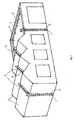
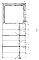
- Figs 1 and 2 illustrate schematically an embodiment of a FAS according to the invention when installed on a building.
- the FAS describes a continuous safety track which runs alongside a worker's typical climbing route and walkway. It consists of vertical track parts 1 installed on ladders 2, inclined track parts 3 installed on pitched rooftops 4, and horizontal track parts 5, installed in the valleys of the pitched roofs and on a flat roof 6.
- the track is held closely spaced from the structure by supports 7 which are attached by bolts to the structure.
- a sliding device (not shown in Figs 1 or 2) is engaged onto the track to be freely displaceable thereon during normal movement of a worker attached to the sliding device by means of a safety line, the sliding device having a locking mechanism a portion of which engages the track to lock the sliding device onto the track in the event of a fall by the worker.
- the safety track is so installed as to allow changes in direction of the sliding device when engaged on the track, by utilising turntable devices 8, tilting changeover mechanisms 9, or bends 10. End stops 11 prevent the inadvertent disengagement of the sliding device from the ends of the track.
- the inclined parts of the safety track have integral steps 12 and guard rails 13 to assist a worker in climbing up or down the inclined surface.
- the guard rails 13 may be permanently erect, or may be so constructed as to have a hinge mechanism, to allow the guard rail to be pivoted down and stowed flush to the roof surface after use (see Fig 6). When it needs to be erected for future use a catch can be released by the worker and it can be rotated upwards into the erect position.
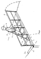
- Fig 3 illustrates schematically an embodiment of the FAS according to the invention illustrated installed on a pylon for supporting electrical transmission cables.
- the FAS describes a continuous safety track which runs alongside a worker's typical climbing route and walkway consisting of vertical or near-vertical track parts 1 installed on ladders 2, inclined track parts 3 on the bottom of the outriggers, and horizontal track parts 5 installed across members and outriggers.
- the track is held closely spaced from the structure by supports which are attached by bolts to the structure.
- the safety track is so installed as to allow changes in direction of the sliding device when engaged on the track, by utilising turntable devices 8 and tilting changeover mechanisms 9. End stops 11 prevent the inadvertent disengagement of the sliding device from the ends of the track.
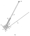
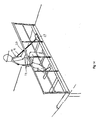
- the FAS illustrated and fastened onto an installed ladder 2 in the vertical plane in Fig 4 describes the vertical track part 1 of a FAS according to the present invention.
- This vertical track part could be part of a continuous safety track which runs alongside a worker's typical climbing route and walkway, consisting of any number and combination of track parts in the vertical, horizontal and inclined planes, or could itself be the entire safety track. It consists of the track part which is held closely spaced from the ladder by supports 7 which are attached to the ladder rungs.
- the worker is wearing a safety harness 14, which is connected at a frontal harness attachment point (HAP) 15 to the safety line 16 of the sliding device 17.
- HAP frontal harness attachment point
- the detail of the worker's right arm has been removed to show the detail of the HAP 15 and safety line 16 attached thereto.
- the safety line 16 is of fixed length whilst the invention is operated in the vertical plane, which causes the sliding device 17 to be pushed up the safety track 1, ensuring that the HAP 15 always remains below the sliding device 17.
- the FAS illustrated and fastened onto the structure in the horizontal plane in Fig 5 describes the horizontal track part 5 of a FAS according to the present invention.
- the horizontal track part 5 could be part of a continuous safety track which runs alongside a worker's typical climbing route and walkway, consisting of any number and combination of track parts in the vertical, horizontal and inclined planes, or could itself be the entire safety track. It consists of the track 5 that is held closely spaced to the structure by supports (not shown) which are bolted to the structure.
- the workers are wearing safety harnesses 14 which are connected at a dorsal HAP 18 to the safety line 16 of the sliding device 17.
- the safety line 16 is extendable and retractable whilst the invention is operated in the horizontal plane, up to a maximum determined by the storage capacity of a reel within the sliding device 17.
- the retractable nature of the safety line 16 ensures that irrespective of the worker's position, the safety line 16 maintains the shortest possible length between the HAP 18 and the sliding device 17, which minimises free fall in an accident.
- the design features of the sliding device 17 enable it to be pulled along the track in response to worker movement so that the sliding device 17 trails behind the worker.
- the FAS illustrated and fastened onto the roof structure in the inclined plane in Fig 6 describes the inclined track part 3 of a FAS according to the present invention.
- the inclined track part 3 could be part of a continuous safety track which runs alongside a worker's typical climbing route and walkway, consisting of any number and combination of track parts in the vertical, horizontal and inclined planes, or could itself be the entire safety track. It consists of the track 3 which is held closely spaced to the structure by supports (not shown) which are bolted to the structure.
- the worker is wearing a safety harness 14 which is connected at a dorsal HAP 18 to the safety line 16 of the sliding device 17.
- the steps 12 and guard rail 13 may be integral to the track 3 in order to assist a worker in climbing up and down the inclined surface.
- the guard rail 13 may be permanently erected or may be so constructed as to have a hinge and catch mechanism to allow the guard rail to be pivoted down as indicated by the broken lines and stowed flush to the roof surface after use. When required for future use the hinge and catch mechanism can be operated and the guard rail 13 can be pivoted upwards as indicated by the broken lines and locked into the erect position.
- the safety line 16 is extendable and retractable whilst the FAS is operated in the inclined plane, up to a maximum determined by the storage capacity of the reel within the sliding device.
- the retractable nature of the safety line 16 ensures that irrespective of the worker's position, the safety line 16 maintains the shortest possible length between HAP 18 and the sliding device 17, which minimises free fall in an accident.
- the design features of the sliding device 17 enable it to be pulled along the track 3 in response to worker movement so that it trails behind the worker.
- the same features and trailing operation of the sliding device 17 allow the worker to climb over the ridge, and to walk down the opposite surface of the roof.
- Fig 6 shows the track 3 and integral pivoting guard rail 13 on an inclined surface, it is anticipated by the present invention that such features may also utilised on a horizontal surface.
- Fig 6 shows the base of guard rail 13 being integral to the track 3, it is anticipated by the present invention that the track 3 may instead be integral to, or may replace either the upper rail or middle rail of the guard rail 13, or may be integral to or be attached to any part of the guard rail 13.
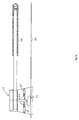
- a rigid rail 1 and sliding device 17 in Figs 7a and 7b shows one example of an embodiment of the present invention.
- the rail 1 is of a hollow "X" section manufacture which can be joined at pre-determined intervals, and is installed to the host structure by supports 7 and bolts.
- the channel 20 within the rail can be used to accommodate anti-icing means to prevent the rail from icing up in inclement weather, which otherwise would prevent free passage of the sliding device.
- Wheels 21 are attached to the sliding device by spigots 22 and locate onto the flanges of the rail in such a manner as to prevent the sliding device 17 from disengaging from the rail at any point.
- the wheels 21 allow the sliding device 17 to be guided along the rail.
- a variable length safety line 16 is contained on a reel 23, together with a braking mechanism for the safety line 16, within the housing 24 of the sliding device 17.
- the housing 24 is moveably mounted on the sliding device 17.
- the safety line 16 is encased by a substantially rigid tube 25.
- the tube 25 ensures that the safety line 16 remains substantially rigid in properties when the track is oriented in the vertical plane, but flexible and automatically extendable and retractable when the track is oriented in the horizontal and inclined planes.
- the sectioned views in Figs 8a and 8b describe the method of working of the sliding device 17 of Figs 7a and 7b whilst in the vertical plane (when operating as shown in Fig 4).
- the guiding wheels 21 of the sliding device 17 and track detail have been omitted for clarity, except that of the track surface 26 on which the locking mechanism acts.
- the locking mechanism consists of a locking lever 27 and a gravity switch, which consists of a tube 28, and pellets 29, 29'.
- the locking lever 27 is pivotally mounted on a pin 30, and can rotate about said pin 30, such rotation being resisted by spring action which urges the locking lever 27 towards the neutral position, i.e. that position when the locking lever is perpendicular to the track surface.
- the distal end of the locking lever 27 also engages with the safety line housing 24, which is mounted on and can slide in relation to the sliding device 17.
- the locking lever 27 has a locking pawl 31 which may be lined with a braking material, and has integral pips 32, 32', which are designed to work in concert with the gravity switch.
- the pellets 29, 29' are free to slide up and down the gravity switch tube 28, and are prevented from falling out of the tube by end caps 33.
- the gravity switch tube 28 has slots to allow the pips 32, 32' to enter said tube 28 as a result of the rotation of the locking lever 27.
- the safety line housing 24 contains a reel 34, braking mechanism 35, and safety line 16. During manufacture, one end of the safety line 16 is secured to the reel 34, and the safety line 16 is then progressively wound onto the reel 34, and exits the housing 24 at an exit bush.
- the reel 34 is mounted onto an axle (indicted by centreline), allowing it to rotate. It is restrained in one direction by a clock spring (not shown) contained inside the reel 34 and is attached to the housing 24. The effect of this design is to ensure that the safety line 16 is always subjected to a light restraining tension, caused by the action of the clock spring.
- the safety line 16 is extracted under a light tension, and as the worker comes nearer the sliding device 17, the safety line 16 is automatically retracted. This ensures that the safety line 16 is always the shortest possible distance between the worker and the sliding device 17 without having any slack in the line.
- the braking mechanism 35 is a clutch arrangement mounted on the axle which consists of a fixed brake assembly which is attached to the housing 24, and brake locking pawls (not shown) which are attached to the reel. Both the fixed brake assembly and the brake locking pawls / reel 34 are designed to lock together as one part under fall arrest conditions, but to remain separate under all other conditions.
- the fixed brake assembly is designed to absorb energy generated from a fall.
- a free-floating pipe 25 which is substantially rigid in properties covers the safety line 16 without restricting the extraction and retraction of safety line 16.
- the pipe 25 also abuts against the housing 24 and the safety line termination such that a fixed length of safety line 16 is kept permanently outside the housing 24.
- a connector 36 can be used to connect the safety line 16 to a worker's safety harness.
- Fig 8a which is the mode of operation of the sliding device 17 during climbing movement in the vertical plane, (as shown in Fig 4), the lower pellet 29' falls to the bottom of the tube 28 under the action of gravity, and the upper pellet 29 similarly falls until it makes contact with locking lever 27.
- Pushing forces from climbing movements are transmitted up the pipe 25 to the housing 24, which pushes the locking lever 27 upwards about the pin 30.
- the upper pip 32 abuts the upper pellet 29, which prevents further movement of the locking lever 27, and prevents the locking pawl 31 from making contact with the track surface 26.
- the pushing forces from climbing movement causes the whole sliding device 17 to slide up the track.
- the position of the locking pawl 31 remains in close proximity with the track surface 26.
- Fig 8b illustrates the operation of the sliding device 17 should a fall occur. Since virtually no free fall is experienced by the worker, the safety line 16 is extracted immediately at an increasing speed since the worker falls at the acceleration due to gravity. The reel 34 is accordingly imparted rotational acceleration until a pre-determined rotational velocity is achieved whereupon the brake locking pawls engage with the fixed brake assembly, causing the reel 34 to instantly stop rotating. This causes the locking lever 27 to be pulled sharply downwards, causing the locking pawl 31 to interfere with the track surface 26, bringing the sliding device 17 to a complete halt. Any fall-generated energy developed during this period is then absorbed by the fixed brake assembly 35, which resists subsequent downward motion by applying a braking force, and which results in some extraction of the safety line 16, which is exposed as the pipe 25 slides down the safety line 16 from the housing 24.
- variable length safety line can be replaced with a substantially rigid fixed length safety line, attached to locking lever and to the worker's safety harness.
- the sectioned partial view in Fig 9 describes the method of working of the sliding device 17 whilst in the inclined plane, i.e. when ascending (Fig 6) or descending the same inclined surface, or when ascending and descending the sides of a pitched roof.
- the guiding wheels of the sliding device and track details have been omitted for clarity, except that of the track surface 26 on which the locking mechanism acts.
- the description of the sliding device 17 and the variable length safety line 16 is identical to that described under Figs 8a and 8b.
- the pip 32' After a certain amount of movement of the locking lever 27, the pip 32' abuts the upper pellet 29', which prevents further movement of the locking lever 27, and prevents the locking pawl 31 from making contact with the track surface 26. Whereupon the pulling forces from climbing movement causes the whole sliding device to slide up the track. The position of the locking pawl 31 remains in close proximity with the track surface 26. In the descent situation the pellets 29, 29' and the locking lever 27 remain in the same position and the weight of sliding device 17 enables it to slide down the track.
- variable length safety line can be replaced with a fixed length safety line, attached to the locking lever and to the worker's safety harness.
- FIG 10 The sectioned partial view in Fig 10 describes the method of working of the sliding device 17 whilst in the horizontal plane (as shown in Fig 5).
- the guiding wheels of sliding device and track details have been omitted for clarity, except that of the track surface 26 on which the locking mechanism acts.
- the description of the sliding device 17 and variable length safety line 16 is identical to that described under Figs 8a and 8b.
- the position of the pellets 29, 29' is irrelevant since the locking of the sliding device 17 on the track surface is not required. This is due to the fact that any fall arrest force applied will be perpendicular to the track, so that the track on its own provides a reaction to the fall.
- the locking lever 27 adopts a near neutral position and extraction of the safety line 16 occurs due to the position of the HAP on the safety harness and the height of the worker.
- the pipe 25 slides away from the safety line housing 24. Pulling forces due to traversing movements in the horizontal which when balanced with the safety line reel clock spring are transmitted to the safety line housing 24.
- the spring bias of the locking lever 27 ensures that it remains in an approximate neutral position which prevents the locking pawl 31 from making contact with the track surface 26. Whereupon the pulling forces from traversing movement causes the whole sliding device 17 to slide along the track.
- variable length safety line can be replaced with a fixed length safety line, attached to the locking lever and to the worker's safety harness.
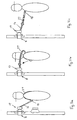
- Figs 11 a, 11b and 11c respectively show three schematic views of the process of changing the HAP position from the frontal 15 to dorsal 18 positions when moving from the vertical plane of movement to the horizontal or inclined planes of movement.
- the worker has ascended to a position where the sliding device 17 previously (indicated by broken line) on a vertical track has been transferred by a turntable 8 onto a horizontal track, where the sliding device is now ready to slide in the horizontal plane. The worker is still facing the track as a result of being connected into the FAS at the frontal HAP 15.
- the HAP changeover feature which is an integral part of the safety harness worn by the worker consists of a safety catch, an extension strap 37, which is stowed with one of the shoulder straps of the safety harness, and is directly attached at the dorsal HAP position 18.
- the worker now can face away from the track and can proceed to traverse horizontally along horizontal track part.
- the extension strap 37 remains attached to the safety harness at the dorsal position 18 and to the safety line 16 via the HAP.
- a tilting changeover device 9 can be utilised. Examples of such situations include transiting from the vertical plane to the inclined plane over the eaves of a roof, and vice versa, transiting upward from one inclined surface of a pitched roof over the ridge to the opposite downwards-facing surface, and negotiating an external corner in the horizontal plane.
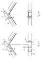
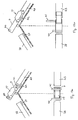
- the sequence of events which allow the sliding device 17 to move through such an abrupt change of direction using the tilting changeover device 9 are shown in Figs 12a, 12b, 13a and 13b.
- Figs 12a and 12b the tilting changeover device (TCD) 9 is shown mounted to the ridge of a roof by a pivot arrangement. Each view shows a side elevation and a plan elevation underneath.
- the sliding device 17 is being pulled up the exiting track 38, i.e. the end of the track run that the sliding device 17 is exiting into the TCD 9.
- the TCD 9 is held and kept in line with the track by the locking catch 39.
- the first retaining pin 40 may either be disengaged automatically by the movement of the sliding device 17 as shown, or this may be done manually, to allow the sliding device 17 in.
- the second retaining pin 41 remains engaged and acts as a stop to prevent the sliding device 17 from leaving the TCD 9.
- Fig 12b the sliding device 17 has been positioned fully within the TCD 9 and the first retaining pin 40 may either lock automatically shut under the influence of a spring or may be engaged manually. With both retaining pins 40, 41 fully engaged the sliding device 17 cannot slide out of the TCD 9 during the next sequence which involves the pivoting of the whole assembly.
- Figs 13a and 13b the TCD 9 arrangement is identical to that shown in Figs 12a and 12b.
- the sequence proceeds when the locking catch 39 on the exiting track 38 is disengaged, which allows the TCD 9 and sliding device 17 to be pivoted through the necessary angle, and automatically engages with the locking catch 42 on the recipient track 43 when the TCD 9 is properly aligned.
- the TCD 9 is held and kept in line with the track 43 by the locking catch 42. Both retaining pins 40, 41 prevent the sliding device 17 from leaving the TCD 9 inadvertently.
- Fig 14 shows another embodiment of the invention, the features of which allow the sliding device 17 to be pushed ahead in response to worker movement. This approach further reduces the amount a worker could fall in a fall incident, and is similar to the method utilised for the vertical plane. Fig 14 also shows the guard rail 13 features previously mentioned.
- the worker wears the safety harness 14, which is connected at the frontal HAP 15 to the safety line 16 of the sliding device 17.
- the worker Prior to climbing up the inclined surface, the worker extends the substantially rigid tube 25 that encases the safety line 16, which accordingly extracts the safety line 16 from the housing 24.
- This apparatus is also utilised in the vertical plane to ensure that the sliding device 17 is pushed up the track 1 in response to worker movement).
- This extension is achieved by a telescoping action, which automatically locks when of the correct length, encasing what amounts to a fixed length of safety line 16.
- Pushing forces from climbing movements are then transmitted up the tube 25 to the housing 24 of the sliding device 17, which causes the locking mechanism to operate as described above in relation to Figs 8a and 8b.
- a further advantage of this arrangement is that should a worker fall through the inclined surface, e.g. through a fragile surface such as a roof light, the tube 25 provides protection against the shearing action of the safety line 16 on any sharp or abrupt edge.
- the track of the FAS may either be mounted to an existing ladder or may be incorporated into a ladder as part of its manufacture. In the latter case this may result in a single or double-stiled ladder, which may have adjustable rung intervals to suit different anthropometric ranges of climbers' dimensions in different countries.
- rest platforms may be installed at intervals up the ladder.
- Gate devices may be installed at any point on the track, irrespective of orientation, to allow the sliding device to be attached or detached at those points according to work requirements.
- an opening device may be incorporated within the sliding device itself, to allow it to be attached to or detached from the track at any point.
- Turntables or switches which enable a worker to transfer the sliding device from plane to plane, or to transfer between near-parallel routes.
Landscapes
- Engineering & Computer Science (AREA)
- Mechanical Engineering (AREA)
- Health & Medical Sciences (AREA)
- General Health & Medical Sciences (AREA)
- Business, Economics & Management (AREA)
- Emergency Management (AREA)
- Emergency Lowering Means (AREA)
- Walking Sticks, Umbrellas, And Fans (AREA)
Claims (26)
- Absturzsicherungssystem für Personen, die in einer Höhe an einer Struktur mit länglichen Führungs- oder Bahnmitteln (1,3,5) in der Form einer Schiene, eines Seils, eines Kabels oder dergleichen arbeiten, das an der Struktur (4) so festlegbar ist, dass es benachbart zu einer beabsichtigten Route einer Person liegt, die die Struktur besteigt und/oder überquert und/oder von der Struktur absteigt, mit einer Gleiteinrichtung (17), die an die Führungs- oder Bahnmittel angekoppelt ist, um daran entlang frei verschiebbar zu sein, einer Sicherheitsleine (16), die sich von der Gleiteinrichtung (17) zur Befestigung bis an einen Geschirrbefestigungspunkt eines Sicherheitsgeschirrs (14) erstreckt, das von einer Person getragen wird, wobei die Gleiteinrichtung (17) Verriegelungsmittel (27,28,29, 29',31,32,32') umfasst, die es der Gleiteinrichtung erlauben, frei entlang der Führungs- oder Bahnmittel während einer normalen Bewegung einer Person zu gleiten, die damit mittels der Sicherheitsleine (16) verbunden ist, jedoch automatisch die Gleiteinrichtung mit den Führungs- oder Bahnmitteln verriegelt für den Fall, dass eine Person von der Struktur fällt oder stürzt, dadurch gekennzeichnet, dass wenigstens ein Abschnitt der Sicherheitsleine (16) von einem oder einer festen oder starren oder im Wesentlichen starren Rohr oder Röhre (25) umgeben ist oder wenigstens ein Abschnitt der Sicherheitsleine starr oder im Wesentlichen starr ist, so dass, wenn der Abschnitt der Führungs- oder Bahnmittel, an dem die Gleiteinrichtung (17) positioniert ist, in einer vertikalen oder geneigten Richtung orientiert wird, die Gleiteinrichtung an dem Geschirrbefestigungspunkt (18) mittels des Rohrs oder der Röhre (25) oder des im Wesentlichen starren Abschnitts der Sicherheitsleine (16) abgestützt ist, wobei die Gleiteinrichtung (17) über dem Geschirrbefestigungspunkt (18) gehalten ist und wobei der Abstand minimiert ist, durch den eine Person frei fallen kann, bevor die Verriegelungsmittel (27,28,29,29',31,32,32') im Falle eines Sturzes betätigt werden.
- Absturzsicherungssystem nach Anspruch 1, wobei das oder die feste oder starre oder im Wesentlichen starre Rohr oder Röhre (25), das die Sicherheitsleine (16) umhüllt, daran entlang gleitbar ist.
- Absturzsicherungssystem nach Anspruch 1 oder 2, wobei die Sicherheitsleine (16), die von dem festen oder starren oder im Wesentlichen starren Rohr (25) umgeben ist, ausziehbar ist, indem sie auf einer federbelasteten Rolle innerhalb des Körpers der Gleiteinrichtung (17) aufgewickelt ist, so dass sie selbsttätig ausziehbar und einziehbar ist, und einen weiteren Verriegelungsmechanismus (35) umfasst, um die Rolle zu verriegeln, wenn die Geschwindigkeit der Rolle eine vorbestimmte Grenze im Falle eines Sturzes übersteigt.
- Absturzsicherungssystem nach einem der Ansprüche 1 bis 3, wobei das Rohr (25) eine feststehende Länge aufweist.
- Absturzsicherungssystem nach einem der Ansprüche 1 bis 3, wobei das Rohr (25) teleskopierbar ausziehbar und einziehbar ist, um die Länge des im Wesentlichen starren Abschnitts der Sicherheitsleine anzupassen.
- Absturzsicherungssystem nach einem der vorhergehenden Ansprüche, wobei die Verriegelungsmittel die Gleiteinrichtung mit den Führungs- oder Bahnmitteln als Folge einer Zugkraft verriegeln, die auf die Gleiteinrichtung (17) mittels der Sicherheitsleine (16) aufgebracht wird, wenn die Kraft eine Komponente aufweist, die parallel zu den Führungs- oder Bahnmitteln in einer Richtung von der Gleiteinrichtung weg geht.
- Absturzsicherungssystem nach einem der vorhergehenden Ansprüche, wobei die Verriegelungsmittel einen Verriegelungshebel (27) aufweisen, der drehbar innerhalb eines Gehäuses (24) der Gleiteinrichtung zur Rotation um eine Achse montiert ist, wobei einer solchen Rotation durch eine Federwirkung Widerstand geleistet wird, die den Verriegelungshebel (27) in Richtung auf eine neutrale Position drängt, wobei sich der Verriegelungshebel im rechten Winkel zu den Führungs- oder Bahnmitteln erstreckt, wobei das distale Ende des Verriegelungshebels, das am weitesten von den Führungs- oder Bahnmitteln entfernt ist, mit der Sicherheitsleine (16) verbunden ist, und das gegenüberliegende Ende des Verriegelungshebels eine Verriegelungssperre (31) aufweist, wobei eine Drehbewegung des Verriegelungshebels in jeder Richtung aus der neutralen Position als Folge einer Kraft, die auf das gegenüberliegende Ende des Verriegelungshebels über die Sicherheitsleine in einer Richtung parallel zu den Führungs- und Bahnmitteln und weg von der Gleiteinrichtung aufgebracht wird, die Verriegelungssperre in Kontakt mit der Oberfläche der Führungs- oder Bahnmittel bringt.
- Absturzsicherungssystem nach Anspruch 7, wobei die Verriegelungssperre mit einem Bremsmaterial ausgekleidet ist.
- Absturzsicherungssystem nach Anspruch 7 oder 8, wobei Stoppmittel (29,29') vorgesehen sind, die die Verriegelungssperre (31) von einer Betätigung der Oberfläche der Führungs- oder Bahnmittel abhalten, wenn eine Kraft auf den Verriegelungshebel über die Sicherheitsleine in einer Richtung parallel zu den Führungs- und Bahnmitteln und auf die Verriegelungseinrichtung aufgebracht wird, wobei die Verriegelungseinrichtung daran gehindert wird, betätigt zu werden, wenn eine stoßende Kraft auf die Gleiteinrichtung über die Sicherheitsleine aufgebracht wird.
- Absturzsicherungssystem nach einem der vorhergehenden Ansprüche, wobei die Führungs- oder Bahnmittel (3,13) eine im Wesentlichen starre Schiene (1) mit sich nach außen erstreckenden Flanschabschnitten aufweisen, wobei die Gleiteinrichtung (17) Räder (21) umfasst, die die Rückseiten der Flanschabschnitte betätigen, wobei der Gleiteinrichtung erlaubt wird, entlang der Schiene zu gleiten, jedoch die Gleiteinrichtung daran gehindert wird, aus der Schiene gezogen zu werden in eine Richtung quer zur Schienenoberfläche.
- Absturzsicherungssystem nach Anspruch 10, wobei die Schiene (1) einen hohlen Abschnitt hat, der einen Kanal (20) definiert, der entlang der Länge der Schiene läuft und in dem Heizmittel vorgesehen werden können, um zu verhindern, dass sich Eis auf der Schiene bildet, das ansonsten einen freien Durchgang der Gleiteinrichtung (17) behindern würde.
- Absturzsicherungssystem nach Anspruch 11, wobei die Heizmittel einen Strom an aufgeheizter Flüssigkeit aufweisen, der durch den Kanal (20) gelangt, oder eine elektrisches Heizmittel aufweisen.
- Absturzsicherungssystem nach einem der vorhergehenden Ansprüche, wobei eine Absturzsicherung (13) benachbart zur beabsichtigten Route einer Person vorgesehen ist, die die Struktur besteigt und/oder überquert und/oder von der Struktur absteigt, wobei die Führungs- oder Bahnmittel (3) integral mit der Absturzsicherung gebildet sind.
- Absturzsicherungssystem nach einem der vorhergehenden Ansprüche, bei dem die Verriegelungseinrichtung zu einer Verriegelungsbewegung der Gleiteinrichtung an der Führung oder Bahn unabhängig von der Orientierung des Abschnitts der Führungs- oder Bahnmittel fähig ist, auf der die Gleiteinrichtung positioniert ist.
- Absturzsicherungssystem nach einem der Ansprüche 1 bis 14, wobei die Verriegelungsmittel (27,28,29,29',31,32,32') die Bewegung der Gleiteinrichtung (17) als Antwort auf eine Kraft verriegeln, die über die Sicherheitsleine (16) im Falle eines Sturzes einer damit verbundenen Person aufgebracht wird.
- Absturzsicherungssystem nach einem der Ansprüche 14 oder 15, wobei die Verriegelungsmittel (27,28,29,29',31,32,32') einen Verriegelungshebel aufweisen, der drehbar innerhalb eines Gehäuses der Gleiteinrichtung (17) zur Rotation um eine Achse montiert ist, wobei einer derartigen Rotation durch eine Federwirkung Widerstand geleistet wird, die den Verriegelungshebel in eine neutrale Position drängt, wobei der Verriegelungshebel sich im rechten Winkel zu den Führungs- oder Bahnmitteln erstreckt, wobei das distale Ende des Verriegelungshebels, das am weitesten von den Führungs- oder Bahnmitteln entfernt ist, mit der Sicherheitsleine verbunden ist und das gegenüberliegende Ende des Verriegelungshebels eine Verriegelungssperre aufweist, wobei eine Drehbewegung des Verriegelungshebels in jeder Richtung aus der neutralen Position als Antwort auf eine Kraft, die auf das gegenüberliegende Ende des Verriegelungshebels mittels der Sicherheitsleine in einer Richtung parallel zu den Führungs- oder Bahnmitteln und weg von der Gleiteinrichtung aufgebracht wird, die Verriegelungssperre in Kontakt mit der Oberfläche der Führungs- oder Bahnmittel bringt.
- Absturzsicherungssystem nach Anspruch 16, wobei die Verriegelungssperre mit einem Bremsmaterial ausgekleidet ist.
- Absturzsicherungssystem nach Anspruch 17 oder 18, wobei Stoppmittel (29,29') vorgesehen sind, die die Verriegelungssperre (31) an einer Betätigung der Oberfläche der Führungs- oder Bahnmittel hindern, wenn eine Kraft auf den Verriegelungshebel (27) mittels der Sicherheitsleine in einer Richtung parallel zu den Führungs- oder Bahnmitteln und auf die Verriegelungseinrichtung aufgebracht wird, wobei die Verriegelungsmittel daran gehindert werden, betätigt zu werden, wenn eine stoßende Kraft auf die Gleiteinrichtung über die Sicherheitsleine aufgebracht wird.
- Absturzsicherungssystem nach einem der Ansprüche 1 bis 18, die auch ein Sicherheitsgeschirr (14) umfasst, dass von einer Person getragen wird, um die Person im Falle eine Sturzes aus der Höhe zu schützen, wobei dass Sicherheitsgeschirr Bandmittel aufweist, die sich über einen Abschnitt eines Körpers einer Person erstrecken, um eine Person innerhalb des Sicherheitsgeschirrs zurückzuhalten, wobei ein Extensionsgurt sich von einem hinteren Abschnitt des Geschirrs erstreckt, welcher Abschnitt bei Gebrauch benachbart zum Rücken des Trägers ist, wobei Befestigungsmittel benachbart zu dem Extensionsgurt oder an einem distalen Ende des Extensionsgurts zur Verbindung mit einer Sicherheitsleine oder einem Lanyard (16) vorgesehen sind und Verbindungsmittel (15) an einem vorderen Abschnitt des Sicherheitsgeschirrs vorgesehen sind, welcher Abschnitt bei Gebrauch benachbart zur Brust des Trägers ist, wobei die Befestigungsmittel des Extensionsgurts lösbar mit den Verbindungsmitteln verbindbar sind, so dass, wenn das Befestigungsmittel mit dem Verbindungsmittel verbunden ist, das Befestigungsmittel einen vorderen Geschirrbefestigungspunkt (15) für die Sicherheitsleine vorsieht und, wenn das Befestigungsmittel nicht mit dem Verbindungsmittel verbunden ist, das Befestigungsmittel einen dorsalen Geschirrsbefestigungspunkt für die Sicherheitsleine kraft des Extensionsgurts vorsieht, wobei die Anordnung es dem Geschirrbefestigungspunkt erlaubt von den vorderen zu den dorsalen Stellungen bewegt zu werden und umgekehrt, ohne dass eine Aufhebung der Verbindung der Sicherheitsleine mit den Befestigungsmitteln erforderlich ist und eine Ausdehnung der Sicherheitsleine vorgesehen ist, wenn sie mit dem dorsalen Geschirrbefestigungspunkt kraft des Extensionsgurts verbunden ist.
- Absturzsicherungssystem und Sicherheitsgeschirr nach Anspruch 19, wobei, wenn die Befestigungsmittel des Extensionsgurts mit den Verbindungsmitteln auf der Vorderseite des Geschirrs verbunden sind, die Dehnleine über eine Schulter des Trägers gelangt.
- Absturzsicherungssystem nach einem der Ansprüche 1 bis 20, wobei sie auch eine Führungseinrichtung für das Absturzsicherungssystem mit einem ersten Führungsabschnitt (38), der um einen ersten Winkel geneigt ist, und einem zweiten Führungsabschnitt umfasst, der um einen zweiten Winkel geneigt ist, wobei der zweite Winkel vom ersten Winkel verschieden ist und eine Übergangseinrichtung (9) vorgesehen ist, wobei die Übergangseinrichtung es einer Gleiteinrichtung erlaubt, die gleitbar an der Führung montiert ist, von dem ersten Führungsabschnitt zum zweiten Führungsabschnitt zu gelangen, ohne von der Führungseinrichtung gelöst zu werden, wobei die Übergangseinrichtung (9) einen schwenkbaren Abschnitt an Bahn oder Führung aufweist, der drehbar zur Bewegung zwischen einer ersten Position, in der der schwenkbar Abschnitt in Linie mit dem ersten Führungsabschnitt ist und eine Fortsetzung des ersten Führungsabschnitts bildet, und einer zweiten Position montiert ist, in der der Abschnitt der Führung oder Bahn in Linie mit dem zweiten Führungsabschnitt ist und eine Fortsetzung des zweiten Führungsabschnitts bildet, wobei erste und zweite Verriegelungsmittel (39,42) zur Verriegelung des schwenkbaren Abschnitts in seiner ersten bzw. zweiten Stellung vorgesehen ist, wobei erste und zweite Rückhaltemittel benachbart zu den gegenüberliegenden Enden des schwenkbaren Abschnitts vorgesehen sind, wobei die ersten und zweiten Rückhaltemittel (40,41) unabhängig zwischen einer nicht betriebsfähigen Stellung, in der eine Gleiteinrichtung hinter dem jeweiligen Rückhaltemittel sich bewegen kann, um auf oder von dem schwenkbaren Abschnitt weg zu gelangen, und einer betriebsfähigen Stellung bewegbar ist, in der eine Gleiteinrichtung (17) daran gehindert wird, sich hinter dem jeweiligen Rückhaltemittel zu bewegen.
- Absturzsicherungssystem nach einem Ansprüche 1 bis 21, wobei sie auch eine zusammenklappbare Absturzsicherung (13, Fig. 6) zur Befestigung an einer Struktur benachbart zu einer beabsichtigten Route einer Person umfasst, die die Struktur besteigt und/oder überquert und/oder von der Struktur absteigt, wobei die Absturzsicherung Schwenkmittel aufweist, die es der Absturzsicherung erlaubt zwischen einer aufgerichteten betriebsfähigen Stellung, in der die Absturzsicherung sich im Wesentlichen im rechten Winkel von der Oberfläche der Struktur erstreckt, und einer zusammengeklappten Stellung bewegt zu werden, in der die Absturzsicherung im Wesentlichen parallel zu der Oberfläche der Struktur liegt, wobei Verriegelungsmittel zur Verriegelung der Absturzsicherung sowohl in ihrer betriebsfähigen als auch in der zusammengeklappten Stellung vorgesehen sind.
- Absturzsicherungssystem mit einer zusammenklappbaren Absturzsicherung nach Anspruch 22, wobei die Verriegelungsmittel einen Anschlag oder eine Falle (39) aufweisen, der oder die den Schwenkmitteln zugeordnet ist.
- Absturzsicherungssystem nach einem oder mehreren der Ansprüche 1 bis 23, bei dem bei Gebrauch die Gleiteinrichtung (17) an dem Geschirrbefestigungspunkt über die feste oder starre oder im Wesentlichen starre Sicherheitsleine (16) so abgestützt ist, dass die Gleiteinrichtung (17) über mit dem Geschirrbefestigungspunkt gehalten wird, um relativ zu einer voll flexiblen Sicherheitsleine den Abstand zu verringern, durch den eine Person ansonsten frei fallen kann, bevor das Verriegelungsmittel (27,28,29, 29',31,32,32') im Fall eines Sturzes betätigt wird.
- Absturzsicherungssystem nach einem oder mehreren der Ansprüche 1 bis 23, bei dem bei Gebrauch die Gleiteinrichtung (17) an dem Geschirrbefestigungspunkt mittels einer festen oder starren oder im Wesentlichen starren Sicherheitsleine (16) abgestürzt wird, so dass die Gleiteinrichtung (17) in einer Stellung gehalten wird, um relativ zu einer voll flexiblen Sicherheitsleine den Abstand zu verringern, durch den eine Person ansonsten frei fallen kann, bevor das Verriegelungsmittel (27,28,29,29',31,32,32') im Fall eines Sturzes verriegelt wird.
- Absturzsicherungssystem nach einem oder mehreren der Ansprüche 1 bis 23, bei dem bei Gebrauch die Gleiteinrichtung (17) an dem Geschirrbefestigungspunkt mittels einer festen oder starren oder im Wesentlichen starren Sicherheitsleine (16) abgestützt wird, so dass die Gleiteinrichtung (17) in einer relativ zum Geschirrbefestigungspunkt erhöhten Stellung gehalten wird, um relativ zu einer voll flexiblen Sicherheitsleine den Abstand zu verringern, durch den eine Person ansonsten frei fallen kann, bevor das Verriegelungsmittel im Fall eines Sturzes betätigt wird.
Applications Claiming Priority (3)
| Application Number | Priority Date | Filing Date | Title |
|---|---|---|---|
| GB0107143 | 2001-03-21 | ||
| GB0107143A GB2373537B (en) | 2001-03-22 | 2001-03-22 | Improved fall-arrest system for persons working at height |
| PCT/GB2002/001362 WO2002074389A2 (en) | 2001-03-22 | 2002-03-21 | Improved fall-arrest system for persons working at height |
Publications (2)
| Publication Number | Publication Date |
|---|---|
| EP1370329A2 EP1370329A2 (de) | 2003-12-17 |
| EP1370329B1 true EP1370329B1 (de) | 2006-10-25 |
Family
ID=9911297
Family Applications (1)
| Application Number | Title | Priority Date | Filing Date |
|---|---|---|---|
| EP02708491A Expired - Lifetime EP1370329B1 (de) | 2001-03-22 | 2002-03-21 | Verbessertes absturzsicherungssystem für personen, die in höhe arbeiten |
Country Status (6)
| Country | Link |
|---|---|
| EP (1) | EP1370329B1 (de) |
| AT (1) | ATE343418T1 (de) |
| AU (1) | AU2002242853A1 (de) |
| DE (1) | DE60215621D1 (de) |
| GB (1) | GB2373537B (de) |
| WO (1) | WO2002074389A2 (de) |
Families Citing this family (18)
| Publication number | Priority date | Publication date | Assignee | Title |
|---|---|---|---|---|
| GB2313396B (en) * | 1996-04-18 | 2000-08-30 | Acimex | Fall arrest device |
| GB2398337A (en) * | 2003-02-11 | 2004-08-18 | Stephen Murten | A fall arrest system for use with a ladder |
| GB2398821B (en) * | 2003-02-26 | 2005-01-05 | Central | Safety device |
| GB0525386D0 (en) | 2005-12-13 | 2006-01-18 | Dawson Brian | Safety harness |
| DE102008006611B3 (de) * | 2008-01-29 | 2009-06-25 | Aerialtech Sa | Kontinuierliches Sicherungssystem für Objekte, die gegen Absturz gesichert werden müssen |
| US20100012426A1 (en) * | 2008-07-15 | 2010-01-21 | Convenient Safety Systems, Inc. | Sloped Roof Safety System |
| DE102010004656A1 (de) * | 2010-01-14 | 2011-07-21 | Degen, Burkhard, 60598 | Treppen-Auf- und Abstiegssicherung für sturzgefährdete Personen |
| ES2366529B1 (es) * | 2010-03-12 | 2012-09-10 | Esteban Andres Carignano | Dispositivo de seguridad para personal sanitario de ambulancias |
| GB2521605A (en) * | 2013-12-20 | 2015-07-01 | Melvyn Rowberry Specialist Services Ltd | Walkways |
| CN106310559B (zh) * | 2015-07-07 | 2022-08-19 | 陈李果 | 用于筒体或斜体的坠落防护系挂装置 |
| US10864393B2 (en) | 2016-03-31 | 2020-12-15 | 2Innovate Llc | Fall control system and method of controlling a movement during fall event |
| DE202018004216U1 (de) * | 2018-09-12 | 2018-11-26 | Meißner Sicherheitstechnik GmbH | Arbeitsbühne |
| GB2582897A (en) | 2019-03-04 | 2020-10-14 | Gordon Atkinson Arthur | Improved fall arrest system for a person climbing a ladder |
| CA3198494A1 (en) | 2020-11-19 | 2022-05-27 | Bradley Burke | Fall control system and method of controlling a movement during fall event |
| CN112717298B (zh) * | 2021-01-07 | 2022-11-01 | 明阳智慧能源集团股份公司 | 一种风电塔筒的攀爬安全保护装置及其使用方法 |
| CN115845287A (zh) * | 2022-10-25 | 2023-03-28 | 苏州启阳半导体科技有限公司 | 一种防坠落安全系统 |
| US20250170431A1 (en) * | 2023-11-28 | 2025-05-29 | Honeywell Safety Products Usa, Inc. | Fall arrest system |
| WO2025137464A1 (en) | 2023-12-22 | 2025-06-26 | 2Innovate Llc | Fall control systems and components thereof for controlling a movement during fall event |
Family Cites Families (13)
| Publication number | Priority date | Publication date | Assignee | Title |
|---|---|---|---|---|
| FR836052A (fr) * | 1938-04-02 | 1939-01-10 | Appareil de protection contre les chutes dans le vide | |
| US3217833A (en) * | 1964-06-29 | 1965-11-16 | Delmer W Smith | Safety device |
| US4034828A (en) * | 1975-04-14 | 1977-07-12 | Rose Manufacturing Company | Shock absorbing cable connector |
| DE2626425C2 (de) * | 1976-06-12 | 1982-06-16 | Fa. Fritz Brucklacher, 7101 Ellhofen | Sicherheitsvorrichtung an einer Leiter mit einem Laufwagen |
| US4606430A (en) * | 1985-10-04 | 1986-08-19 | Southern Railway Company | Rail mounted safety restraint device |
| DE3613710C1 (de) * | 1986-04-23 | 1987-09-24 | Fahrleitungsbau Gmbh | Gehsicherung fuer eine Person in einem unterirdischen Kanal oder dergleichen,insbesondere in einem Kanalisationsrohr |
| US4852692A (en) * | 1988-06-30 | 1989-08-01 | Davey Roofing, Inc. | Roofing safety device |
| EP0418405A1 (de) * | 1989-09-16 | 1991-03-27 | Fahrleitungsbau GmbH | Fangeinrichtung für eine Steigschutzeinrichtung |
| GB2253433A (en) * | 1991-02-01 | 1992-09-09 | William Gibson Queen | Safety runner |
| GB2256408A (en) * | 1991-05-23 | 1992-12-09 | Inveteck Plc | Rail trolley for fall arrest equipment. |
| GB2278627B (en) * | 1993-05-28 | 1996-05-15 | Unistrut | Safety tethering system |
| US5694720A (en) * | 1994-04-11 | 1997-12-09 | Safety Equipment, Inc. | Standing clamp for standing seam roof |
| JP2000045535A (ja) * | 1998-07-28 | 2000-02-15 | Ntt Power & Building Facilities Inc | 安全装置 |
-
2001
- 2001-03-22 GB GB0107143A patent/GB2373537B/en not_active Expired - Fee Related
-
2002
- 2002-03-21 DE DE60215621T patent/DE60215621D1/de not_active Expired - Lifetime
- 2002-03-21 WO PCT/GB2002/001362 patent/WO2002074389A2/en not_active Ceased
- 2002-03-21 EP EP02708491A patent/EP1370329B1/de not_active Expired - Lifetime
- 2002-03-21 AT AT02708491T patent/ATE343418T1/de not_active IP Right Cessation
- 2002-03-21 AU AU2002242853A patent/AU2002242853A1/en not_active Abandoned
Also Published As
| Publication number | Publication date |
|---|---|
| WO2002074389A3 (en) | 2003-01-09 |
| WO2002074389A2 (en) | 2002-09-26 |
| EP1370329A2 (de) | 2003-12-17 |
| ATE343418T1 (de) | 2006-11-15 |
| DE60215621D1 (de) | 2006-12-07 |
| AU2002242853A1 (en) | 2002-10-03 |
| GB2373537B (en) | 2005-09-07 |
| GB0107143D0 (en) | 2001-05-09 |
| GB2373537A (en) | 2002-09-25 |
Similar Documents
| Publication | Publication Date | Title |
|---|---|---|
| EP1370329A2 (de) | Verbessertes absturzsicherungssystem für personen, die in höhe arbeiten | |
| EP3935251B1 (de) | Verbessertes absturzsicherungssystem für eine person zum hochklettern einer leiter | |
| US9284777B1 (en) | Fall restraint system for telescoping ladders | |
| ES2153947T5 (es) | Dispositivo de anticaidas movil para soporte de aseguramiento flexible. | |
| CA1201693A (en) | Climbing aid and safety descent device | |
| US9447639B2 (en) | Ladder safety device, systems and methods of arresting falls from ladders | |
| EP3047090B1 (de) | Leitern mit seil- und riemenscheibensystem sowie absturzsicherung | |
| US20100044151A1 (en) | Ladder safety apparatus | |
| EP1759074B1 (de) | Sicherheitsvorrichtung | |
| WO2012035514A1 (en) | A fall protection system | |
| US20110186382A1 (en) | Fall arrest device | |
| EP3722539B1 (de) | Ein festes system zum schutz gegen abstürze aus der höhe | |
| US6095283A (en) | Walk-through ladder | |
| WO2013056353A1 (en) | Trolley comprising a fall arrest actuator | |
| US4770272A (en) | Safety attachment for ladder | |
| WO2004067095A1 (en) | Improved fall restraint system | |
| US4703832A (en) | Safety escape apparatus for elevated structures | |
| EP4667679A1 (de) | Absturzsicherungsvorrichtung | |
| US5161639A (en) | Derrick counterweight assembly | |
| CN219764330U (zh) | 一种具有逃生功能的护栏 | |
| CA2181858A1 (en) | Method and apparatus for prevention of falls from extension ladders | |
| EP3717729B1 (de) | Rettungssystem mit ausziehbarer leiter | |
| CN218129612U (zh) | 多功能消防梯 | |
| EP4450749B1 (de) | Leiterkupplungsanordnung für absturzsicherungssystem | |
| CN217897738U (zh) | 一种通信塔爬梯 |
Legal Events
| Date | Code | Title | Description |
|---|---|---|---|
| PUAI | Public reference made under article 153(3) epc to a published international application that has entered the european phase |
Free format text: ORIGINAL CODE: 0009012 |
|
| 17P | Request for examination filed |
Effective date: 20030922 |
|
| AK | Designated contracting states |
Kind code of ref document: A2 Designated state(s): AT BE CH CY DE DK ES FI FR GB GR IE IT LI LU MC NL PT SE TR |
|
| AX | Request for extension of the european patent |
Extension state: AL LT LV MK RO SI |
|
| 17Q | First examination report despatched |
Effective date: 20040604 |
|
| GRAP | Despatch of communication of intention to grant a patent |
Free format text: ORIGINAL CODE: EPIDOSNIGR1 |
|
| GRAS | Grant fee paid |
Free format text: ORIGINAL CODE: EPIDOSNIGR3 |
|
| RBV | Designated contracting states (corrected) |
Designated state(s): AT BE CH CY DE DK ES FI FR GR IE IT LI LU MC NL PT SE TR |
|
| GRAA | (expected) grant |
Free format text: ORIGINAL CODE: 0009210 |
|
| AK | Designated contracting states |
Kind code of ref document: B1 Designated state(s): AT BE CH CY DE DK ES FI FR GR IE IT LI LU MC NL PT SE TR |
|
| PG25 | Lapsed in a contracting state [announced via postgrant information from national office to epo] |
Ref country code: IT Free format text: LAPSE BECAUSE OF FAILURE TO SUBMIT A TRANSLATION OF THE DESCRIPTION OR TO PAY THE FEE WITHIN THE PRESCRIBED TIME-LIMIT;WARNING: LAPSES OF ITALIAN PATENTS WITH EFFECTIVE DATE BEFORE 2007 MAY HAVE OCCURRED AT ANY TIME BEFORE 2007. THE CORRECT EFFECTIVE DATE MAY BE DIFFERENT FROM THE ONE RECORDED. Effective date: 20061025 Ref country code: AT Free format text: LAPSE BECAUSE OF FAILURE TO SUBMIT A TRANSLATION OF THE DESCRIPTION OR TO PAY THE FEE WITHIN THE PRESCRIBED TIME-LIMIT Effective date: 20061025 Ref country code: NL Free format text: LAPSE BECAUSE OF FAILURE TO SUBMIT A TRANSLATION OF THE DESCRIPTION OR TO PAY THE FEE WITHIN THE PRESCRIBED TIME-LIMIT Effective date: 20061025 Ref country code: FI Free format text: LAPSE BECAUSE OF FAILURE TO SUBMIT A TRANSLATION OF THE DESCRIPTION OR TO PAY THE FEE WITHIN THE PRESCRIBED TIME-LIMIT Effective date: 20061025 Ref country code: LI Free format text: LAPSE BECAUSE OF FAILURE TO SUBMIT A TRANSLATION OF THE DESCRIPTION OR TO PAY THE FEE WITHIN THE PRESCRIBED TIME-LIMIT Effective date: 20061025 Ref country code: CH Free format text: LAPSE BECAUSE OF FAILURE TO SUBMIT A TRANSLATION OF THE DESCRIPTION OR TO PAY THE FEE WITHIN THE PRESCRIBED TIME-LIMIT Effective date: 20061025 Ref country code: BE Free format text: LAPSE BECAUSE OF FAILURE TO SUBMIT A TRANSLATION OF THE DESCRIPTION OR TO PAY THE FEE WITHIN THE PRESCRIBED TIME-LIMIT Effective date: 20061025 |
|
| REG | Reference to a national code |
Ref country code: CH Ref legal event code: EP |
|
| REG | Reference to a national code |
Ref country code: IE Ref legal event code: FG4D |
|
| REF | Corresponds to: |
Ref document number: 60215621 Country of ref document: DE Date of ref document: 20061207 Kind code of ref document: P |
|
| PG25 | Lapsed in a contracting state [announced via postgrant information from national office to epo] |
Ref country code: DK Free format text: LAPSE BECAUSE OF FAILURE TO SUBMIT A TRANSLATION OF THE DESCRIPTION OR TO PAY THE FEE WITHIN THE PRESCRIBED TIME-LIMIT Effective date: 20070125 Ref country code: SE Free format text: LAPSE BECAUSE OF FAILURE TO SUBMIT A TRANSLATION OF THE DESCRIPTION OR TO PAY THE FEE WITHIN THE PRESCRIBED TIME-LIMIT Effective date: 20070125 |
|
| PG25 | Lapsed in a contracting state [announced via postgrant information from national office to epo] |
Ref country code: DE Free format text: LAPSE BECAUSE OF FAILURE TO SUBMIT A TRANSLATION OF THE DESCRIPTION OR TO PAY THE FEE WITHIN THE PRESCRIBED TIME-LIMIT Effective date: 20070126 |
|
| PG25 | Lapsed in a contracting state [announced via postgrant information from national office to epo] |
Ref country code: ES Free format text: LAPSE BECAUSE OF FAILURE TO SUBMIT A TRANSLATION OF THE DESCRIPTION OR TO PAY THE FEE WITHIN THE PRESCRIBED TIME-LIMIT Effective date: 20070205 |
|
| PG25 | Lapsed in a contracting state [announced via postgrant information from national office to epo] |
Ref country code: PT Free format text: LAPSE BECAUSE OF FAILURE TO SUBMIT A TRANSLATION OF THE DESCRIPTION OR TO PAY THE FEE WITHIN THE PRESCRIBED TIME-LIMIT Effective date: 20070326 |
|
| NLV1 | Nl: lapsed or annulled due to failure to fulfill the requirements of art. 29p and 29m of the patents act | ||
| REG | Reference to a national code |
Ref country code: CH Ref legal event code: PL |
|
| EN | Fr: translation not filed | ||
| PLBE | No opposition filed within time limit |
Free format text: ORIGINAL CODE: 0009261 |
|
| STAA | Information on the status of an ep patent application or granted ep patent |
Free format text: STATUS: NO OPPOSITION FILED WITHIN TIME LIMIT |
|
| 26N | No opposition filed |
Effective date: 20070726 |
|
| PG25 | Lapsed in a contracting state [announced via postgrant information from national office to epo] |
Ref country code: IE Free format text: LAPSE BECAUSE OF NON-PAYMENT OF DUE FEES Effective date: 20070321 Ref country code: MC Free format text: LAPSE BECAUSE OF NON-PAYMENT OF DUE FEES Effective date: 20070331 |
|
| PG25 | Lapsed in a contracting state [announced via postgrant information from national office to epo] |
Ref country code: GR Free format text: LAPSE BECAUSE OF FAILURE TO SUBMIT A TRANSLATION OF THE DESCRIPTION OR TO PAY THE FEE WITHIN THE PRESCRIBED TIME-LIMIT Effective date: 20070126 Ref country code: FR Free format text: LAPSE BECAUSE OF FAILURE TO SUBMIT A TRANSLATION OF THE DESCRIPTION OR TO PAY THE FEE WITHIN THE PRESCRIBED TIME-LIMIT Effective date: 20070608 |
|
| PG25 | Lapsed in a contracting state [announced via postgrant information from national office to epo] |
Ref country code: FR Free format text: LAPSE BECAUSE OF FAILURE TO SUBMIT A TRANSLATION OF THE DESCRIPTION OR TO PAY THE FEE WITHIN THE PRESCRIBED TIME-LIMIT Effective date: 20061025 |
|
| PG25 | Lapsed in a contracting state [announced via postgrant information from national office to epo] |
Ref country code: LU Free format text: LAPSE BECAUSE OF NON-PAYMENT OF DUE FEES Effective date: 20070321 Ref country code: CY Free format text: LAPSE BECAUSE OF FAILURE TO SUBMIT A TRANSLATION OF THE DESCRIPTION OR TO PAY THE FEE WITHIN THE PRESCRIBED TIME-LIMIT Effective date: 20061025 |
|
| PG25 | Lapsed in a contracting state [announced via postgrant information from national office to epo] |
Ref country code: TR Free format text: LAPSE BECAUSE OF FAILURE TO SUBMIT A TRANSLATION OF THE DESCRIPTION OR TO PAY THE FEE WITHIN THE PRESCRIBED TIME-LIMIT Effective date: 20061025 |