EP1370334B1 - Element zum verbinden magnetischer befestigungsmodule für die konstruktion stabiler stabkonstruktionen - Google Patents
Element zum verbinden magnetischer befestigungsmodule für die konstruktion stabiler stabkonstruktionen Download PDFInfo
- Publication number
- EP1370334B1 EP1370334B1 EP02724243A EP02724243A EP1370334B1 EP 1370334 B1 EP1370334 B1 EP 1370334B1 EP 02724243 A EP02724243 A EP 02724243A EP 02724243 A EP02724243 A EP 02724243A EP 1370334 B1 EP1370334 B1 EP 1370334B1
- Authority
- EP
- European Patent Office
- Prior art keywords
- joining
- modules
- joining system
- module
- elongated
- Prior art date
- Legal status (The legal status is an assumption and is not a legal conclusion. Google has not performed a legal analysis and makes no representation as to the accuracy of the status listed.)
- Expired - Lifetime
Links
Images


Classifications
-
- A—HUMAN NECESSITIES
- A63—SPORTS; GAMES; AMUSEMENTS
- A63H—TOYS, e.g. TOPS, DOLLS, HOOPS OR BUILDING BLOCKS
- A63H33/00—Other toys
- A63H33/04—Building blocks, strips, or similar building parts
- A63H33/046—Building blocks, strips, or similar building parts comprising magnetic interaction means, e.g. holding together by magnetic attraction
-
- A—HUMAN NECESSITIES
- A47—FURNITURE; DOMESTIC ARTICLES OR APPLIANCES; COFFEE MILLS; SPICE MILLS; SUCTION CLEANERS IN GENERAL
- A47F—SPECIAL FURNITURE, FITTINGS, OR ACCESSORIES FOR SHOPS, STOREHOUSES, BARS, RESTAURANTS OR THE LIKE; PAYING COUNTERS
- A47F5/00—Show stands, hangers, or shelves characterised by their constructional features
- A47F5/14—Tubular connecting elements for wire stands
-
- G—PHYSICS
- G09—EDUCATION; CRYPTOGRAPHY; DISPLAY; ADVERTISING; SEALS
- G09B—EDUCATIONAL OR DEMONSTRATION APPLIANCES; APPLIANCES FOR TEACHING, OR COMMUNICATING WITH, THE BLIND, DEAF OR MUTE; MODELS; PLANETARIA; GLOBES; MAPS; DIAGRAMS
- G09B25/00—Models for purposes not provided for in G09B23/00, e.g. full-sized devices for demonstration purposes
- G09B25/04—Models for purposes not provided for in G09B23/00, e.g. full-sized devices for demonstration purposes of buildings
-
- G—PHYSICS
- G09—EDUCATION; CRYPTOGRAPHY; DISPLAY; ADVERTISING; SEALS
- G09F—DISPLAYING; ADVERTISING; SIGNS; LABELS OR NAME-PLATES; SEALS
- G09F7/00—Signs, name or number plates, letters, numerals, or symbols; Panels or boards
- G09F7/02—Signs, plates, panels or boards using readily-detachable elements bearing or forming symbols
- G09F7/04—Signs, plates, panels or boards using readily-detachable elements bearing or forming symbols the elements being secured or adapted to be secured by magnetic means
-
- E—FIXED CONSTRUCTIONS
- E04—BUILDING
- E04B—GENERAL BUILDING CONSTRUCTIONS; WALLS, e.g. PARTITIONS; ROOFS; FLOORS; CEILINGS; INSULATION OR OTHER PROTECTION OF BUILDINGS
- E04B1/00—Constructions in general; Structures which are not restricted either to walls, e.g. partitions, or floors or ceilings or roofs
- E04B1/18—Structures comprising elongated load-supporting parts, e.g. columns, girders, skeletons
- E04B1/19—Three-dimensional [3D] framework structures
- E04B1/1903—Connecting nodes specially adapted therefor
- E04B1/1906—Connecting nodes specially adapted therefor with central spherical, semispherical or polyhedral connecting element
-
- E—FIXED CONSTRUCTIONS
- E04—BUILDING
- E04B—GENERAL BUILDING CONSTRUCTIONS; WALLS, e.g. PARTITIONS; ROOFS; FLOORS; CEILINGS; INSULATION OR OTHER PROTECTION OF BUILDINGS
- E04B1/00—Constructions in general; Structures which are not restricted either to walls, e.g. partitions, or floors or ceilings or roofs
- E04B1/18—Structures comprising elongated load-supporting parts, e.g. columns, girders, skeletons
- E04B1/19—Three-dimensional [3D] framework structures
- E04B2001/1924—Struts specially adapted therefor
- E04B2001/1927—Struts specially adapted therefor of essentially circular cross section
-
- E—FIXED CONSTRUCTIONS
- E04—BUILDING
- E04B—GENERAL BUILDING CONSTRUCTIONS; WALLS, e.g. PARTITIONS; ROOFS; FLOORS; CEILINGS; INSULATION OR OTHER PROTECTION OF BUILDINGS
- E04B1/00—Constructions in general; Structures which are not restricted either to walls, e.g. partitions, or floors or ceilings or roofs
- E04B1/18—Structures comprising elongated load-supporting parts, e.g. columns, girders, skeletons
- E04B1/19—Three-dimensional [3D] framework structures
- E04B2001/1924—Struts specially adapted therefor
- E04B2001/1933—Struts specially adapted therefor of polygonal, e.g. square, cross section
-
- E—FIXED CONSTRUCTIONS
- E04—BUILDING
- E04B—GENERAL BUILDING CONSTRUCTIONS; WALLS, e.g. PARTITIONS; ROOFS; FLOORS; CEILINGS; INSULATION OR OTHER PROTECTION OF BUILDINGS
- E04B1/00—Constructions in general; Structures which are not restricted either to walls, e.g. partitions, or floors or ceilings or roofs
- E04B1/18—Structures comprising elongated load-supporting parts, e.g. columns, girders, skeletons
- E04B1/19—Three-dimensional [3D] framework structures
- E04B2001/1957—Details of connections between nodes and struts
-
- F—MECHANICAL ENGINEERING; LIGHTING; HEATING; WEAPONS; BLASTING
- F16—ENGINEERING ELEMENTS AND UNITS; GENERAL MEASURES FOR PRODUCING AND MAINTAINING EFFECTIVE FUNCTIONING OF MACHINES OR INSTALLATIONS; THERMAL INSULATION IN GENERAL
- F16B—DEVICES FOR FASTENING OR SECURING CONSTRUCTIONAL ELEMENTS OR MACHINE PARTS TOGETHER, e.g. NAILS, BOLTS, CIRCLIPS, CLAMPS, CLIPS OR WEDGES; JOINTS OR JOINTING
- F16B2200/00—Constructional details of connections not covered for in other groups of this subclass
- F16B2200/83—Use of a magnetic material
-
- Y—GENERAL TAGGING OF NEW TECHNOLOGICAL DEVELOPMENTS; GENERAL TAGGING OF CROSS-SECTIONAL TECHNOLOGIES SPANNING OVER SEVERAL SECTIONS OF THE IPC; TECHNICAL SUBJECTS COVERED BY FORMER USPC CROSS-REFERENCE ART COLLECTIONS [XRACs] AND DIGESTS
- Y10—TECHNICAL SUBJECTS COVERED BY FORMER USPC
- Y10T—TECHNICAL SUBJECTS COVERED BY FORMER US CLASSIFICATION
- Y10T428/00—Stock material or miscellaneous articles
- Y10T428/13—Hollow or container type article [e.g., tube, vase, etc.]
-
- Y—GENERAL TAGGING OF NEW TECHNOLOGICAL DEVELOPMENTS; GENERAL TAGGING OF CROSS-SECTIONAL TECHNOLOGIES SPANNING OVER SEVERAL SECTIONS OF THE IPC; TECHNICAL SUBJECTS COVERED BY FORMER USPC CROSS-REFERENCE ART COLLECTIONS [XRACs] AND DIGESTS
- Y10—TECHNICAL SUBJECTS COVERED BY FORMER USPC
- Y10T—TECHNICAL SUBJECTS COVERED BY FORMER US CLASSIFICATION
- Y10T428/00—Stock material or miscellaneous articles
- Y10T428/13—Hollow or container type article [e.g., tube, vase, etc.]
- Y10T428/1352—Polymer or resin containing [i.e., natural or synthetic]
- Y10T428/139—Open-ended, self-supporting conduit, cylinder, or tube-type article
-
- Y—GENERAL TAGGING OF NEW TECHNOLOGICAL DEVELOPMENTS; GENERAL TAGGING OF CROSS-SECTIONAL TECHNOLOGIES SPANNING OVER SEVERAL SECTIONS OF THE IPC; TECHNICAL SUBJECTS COVERED BY FORMER USPC CROSS-REFERENCE ART COLLECTIONS [XRACs] AND DIGESTS
- Y10—TECHNICAL SUBJECTS COVERED BY FORMER USPC
- Y10T—TECHNICAL SUBJECTS COVERED BY FORMER US CLASSIFICATION
- Y10T428/00—Stock material or miscellaneous articles
- Y10T428/13—Hollow or container type article [e.g., tube, vase, etc.]
- Y10T428/1352—Polymer or resin containing [i.e., natural or synthetic]
- Y10T428/1397—Single layer [continuous layer]
Definitions
- the present invention relates to a joining system to be used in an assembly of modules with magnetic anchorage for the construction of stable grid structures which are used in the sector of games or also in the area of display or furnishing.
- the shape of the original grid structure has to be modified by adding thereto - ad hoc - other modules for ensuring its stability.
- This solution in addition to modifying the original shape of the grid structure required, may cause an excessive increase in the weight and cost of the grid structure itself.
- WO-A-02055168 of the same Applicant provides elements for stabilisation of the grid structure in the form of panels which can be removably fitted in corresponding polygonal areas defined by the modules of the grid structure.
- the main object of the present invention is to provide a joining system for an assembly of modules with magnetic anchorage for the construction of grid structures which achieve, using the same number of magnetic modules, improved resistance to deformation due to stresses of shearing, slipping, torsion or bending.
- Another object of the present invention is to provide a joining system for an assembly of modules with magnetic anchorage for the construction of grid structures with the required shape which have been made stable without the shape having been modified and without the overall cost and weight having been increased excessively.
- a joining system comprising a first joining element for connecting rigidly at least a first and a second elongated modules of the grid structure, according to claim 1, and a second joining elements according to claim 16.
- two or more elongated modules are attached in predefined angular directions but do not come into direct contact one with the other, being connectable via an additional module of the grid structure.
- the joining elements of the present invention can be made in a lightweight and economical material and enable extremely stable grid structures to be obtained without jeopardising the original simplicity and flexibility of assembly,
- the spherical modules 1 are in a ferromagnetic material, for example in mild steel covered with an antioxidant material.
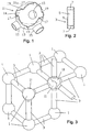
- the cylindrical modules 3 are instead composed of: a cylindrical ferromagnetic pin 5; a pair of cylindrical magnetic elements 7 magnetised axially and attached with opposite magnetic polarity (in Figure 2 n denotes the north polarity and s the south polarity of the magnetic elements 7) at the end bases of the pin 5 coaxially to the pin 5; and a non-magnetic tubular matrix 9 which covers the lateral surface of the pin 5 and magnetic elements 7 and which has the base ends bevelled.
- the joining element 11 comprises a body 13 shaped like a semi-spherical cap or shell .
- the body of the joining element 11 forms a housing 14 defined by the internal surface of the body of the joining element 11 and having radius equal to that of the spherical module 1 of the grid structure to be secured into said housing 14.
- the body of the joining element 11 further has three tubular projections 15, orthogonal one in relation to the other, which extend radially from the same body 13 towards the outside thereof and which have the internal hollow section with radius equal to that of the cylindrical modules 3.
- the tubular projections 15 both have the axially end bases open. Inside the internal radially end base of each tubular projection 15 it is possible to provide a bevelled annular shoulder (not illustrated) acting as a stop for the bevelled edge the matrix 9 covering the cylindrical module 3 in such a way that the radially internal base of the cylindrical element 3 is aligned with the radially internal base of the tubular projection 15.
- the edge of the semi-spherical body 13 has three sections which extend beyond the maximum meridian line 21 of the semi-spherical body 13 defining clips 17, alternating with three recesses 19 of a complementary shape which extend within the maximum meridian line 21 for housing the clips 17.
- the grid structure defines cubic cells whose sides are occupied by the cylindrical modules 3 and whose tops or nodes are instead occupied by the spherical modules 1.
- the joining element 11 is attached to the spherical module 1 before inserting the cylindrical modules 3 in the corresponding projection 15 on the side of the radially external end base of the projection 15.
- the housing 14 of the joining element 11 encapsulates a half-part of the spherical module 1 and each joining element 11 thus remains attached to the spherical module 11 thanks to the hold on the spherical module 1 by the clips 17. Subsequently the cylindrical modules 3 to be contacted to the spherical module 3 encapsulated by the housing 14 of the joining element 11 can be inserted in the projections 15 of the joining element 11.
- the spherical module 1 is arranged in a peripheral node of the grid structure wherein three cylindrical modules 3 have to converge, it is sufficient to attach to the spherical module 1 one single joining element 11, while in the case wherein the spherical module 1 is arranged in an internal node of the grid structure wherein six cylindrical modules 3 have to converge, it is necessary to attach to the spherical module 1 two joinin elements 11 which slot, making the complementary clips 17 and recesses 19 of the two joining elements 11 match in such a way that the projections 15 of the two joining elements 11 are coaxial in pairs.
- the joining elements 11 can be attached in all or, according to the cases, only in some appropriate nodal points of the grid structure, for example in the nodal points of zones of the grid structure most stressed.
- the grid structure can for example be formed by parallelepiped elongated modules and by cubic modules arranged at the nodes of the grid structure.
- the joining element will have a framework formed with orthogonal flat faces matching corresponding faces of a cubic module of the grid structure, and tubular projections which extend from at least two faces of the framework.
- the projections 15 of the joining element 11 can finally be non-aligned one in relation to the other being arranged with an acute or obtuse angle.
- the joining element 11 does not generate undesirable dispersions of magnetic flow from the magnetic circuit which is formed via the modules of the grid structure connected thereby.
- Figures 4 and 5 show a further preferred embodiment of the first joining element according to the present invention wherein the element 11''' for joining cylindrical modules 3''' of the type in Figure 2 comprises three tubular projections 15''', orthogonal one in relation to the other and arranged radially and at a predetermined radial distance from a common centre of symmetry 29.
- the joining element 11''' has a body 33 whereform the projections 15''' extend.
- a body of the joining element is defined by three flattened ribbings 31 which develop between the opposite axial generatrices of the side wall of each pair of adjacent projections 15''' of the joining element 11'''.
- the internal edges 16''' of the flattened ribbings 31 define a surface of an open spherical housing of the body 33 of the joining element 11''' for securing a spherical module 1' into said open housing of the body 33.
- the peripheral spherical surface of the body 33 has radius equal to the radius of the spherical module 1', the latter being preferably of ferromagnetic type.
- the radially internal end bases of the projections 15''' open onto the body 33 in such a way as to be able to directly match with the spherical surface of the spherical ferromagnetic module 1'.
- a bevelled annular shoulder 35 is formed wherein the bevel 25' of the three cylindrical modules 3''' fits, so that each cylindrical module 3''' can be placed in line with the radially internal base of the respective projection 15''' and can touch directly a spherical module 1', while the joining element 11''' remains blocked between the cylindrical modules 3''' and the spherical module 1'.
- the annular shoulder 35 which acts as a stop for the corresponding cylindrical module 3''' plays an important role when a ribbing 31 of the support framework of the joining element 11''' is used in a horizontal position for supporting the corner of a panel or of a shelf to be fixed to the grid structure. In this case the weight of the shelf or of the panel can be discharged and distributed on the vertical cylindrical modules 3''' opposite the ribbings 31 whereon the shelf or panel rests.
- joining element 11''' for the cylindrical modules 3''' can be attached to the spherical surface of the same module 1' and a joining element 11''' can be attached in any portion of the spherical module 1'.
- a cylindrical module 3''' can be connected directly to the spherical module 1' through the open body 33.
- Figure 6 shows a further preferred embodiment of the first joining element 11'''' of the present invention wherein the element 11"" for joining cylindrical modules 3"" of the type in Figure 2 comprises two tubual projections 15"" having the end bases open.
- the projections 15"" are orthogonal one in relation to the other and have attachment axes which extend radially from a common centre.
- the joining element 11"" comprises a body wherfrom the projections 15"" extend.
- the body of the joining element is formed by a plate bent at a right angle.
- the projections 15"" extend from the side of the convex surface of the body 37 and have the radially internal open end base on the body 37, while the concave surface 36 forms a housing for securing a parallelepiped module 39.
- the projections 15"" are also connected by a flat ribbing 31' which extends between the opposite axial generatrices of the side walls of the two projectons 15"".
- a bevelled annular shoulder can be provided (not shown), acting as an a stop for the cylindrical element 3"" inserted in the projection 15"" on the side of the radially external end base of the projection attachment 15"".
- a fixed or removable tooth 41 is formed which can fit into any one of the notches 43 formed at regular intervals on the edge 38 of the ferromagnetic parallelepiped module 39.
- the concave surface 36 of the body 37 matches that of the parallelepiped module 39 and thus allows the two cylindrical modules 3"" to be maintained in direct contact with the parallelepiped module 39.
- the joining element 11"" in this case blocks the relative angular arrangement between the two cylindrical modules 3"" and simultaneously the position of the cylindrical modules 3"" on the longitudinal axis of the ferromagnetic module 39, and can therefore in this case too be used for the support of shelves and/or panels.
- the body of the joining element according to the present invention has to provide a housing for a further module, said housing comprising a surface shaped as the peripheral surface of said further module for engaging said further module.
- Figure 7 shows further preferred embodiments of a second joining element 11" of the present invention which can be used for head-joining two cylindrical modules 3' of the type in Figure 2.
- each joining element 11" has a tubular body having a pair of tubular projections 15', 15' or 15", 15" directly connected one to the other extend.
- the joining element 11' in the point of connection between the projections 15' 15', defines a bevelled internal annular shoulder 23 wherein the bevel 25 of the cylindrical modules 3', in the projections 15', 15', fits.
- the bevelled annular shoulder 23 of the joining element 11' therefore serves as an stop for the two cylindrical modules 3' which, having achieved the position of end of stroke, are joined at the head and in direct contact one with the other.
- an axial spacer 27 with a trapezoidal shape is integrated and which allows two cylindrical modules 3' to be head-joined and at the same time the axial distance between them to be adjusted to a predefined value.
- the axial spacer 27 can be a piece of ferromagnetic material which does not introduce dispersion of magnetic flow at the join or in turn can be a magnetic module oriented in such a way as to combine in series its magnetic potential difference with those installed in the magnetic circuit generated by the grid structure.
- a spacer can be provided even in a right tubular coupling portion between coaxial projections of the body of the joining element.
- Figure 7 therefore discloses a second joining element for the head-joining of two elongated modules to be placed in direct contact one with the other or to be connected with the interposing of an axial spacer directly integrated in the joining element.
- the joining element can be formed by three tubular projections arranged as a "T" or respectively by several projections arranged in a star.
- a ferromagnetic or a magnetic insert in contact with the elongated modules inserted in the attachments can be integrated so as to avoid dispersions of the magnetic flow which is formed via the modules connected by the joining element
- the angular orientation of the projections of the body of a joining element in accordance with the present invention can be different from that shown, for example the projections can form an acute or obtuse angle one in relation to the other.
- the detachment of the elongated module from the assembly is now contrasted not only by the magnetic anchorage force of the elongated module subjected to traction but also by the magnetic anchorage force, evaluated in the direction of traction of the elongated module subjected to traction, exerted by part of the other elongated modules of the assembly connected via the joining element which involves the elongated module subjected to traction.
- the joining elements 11, 11', 11", 11''', 11"" can stiffen the grid structure without altering its appearance and for this reason are preferably made in a transparent and rigid plastic material.
- the cylindrical modules 3, 3', 3''', 3"" are oriented in such a way that the differences of magnetic potential generated by them in the magnetic circuit formed via the grid structure are combined in series.
- the system of stiffening of the present invention enables the procedure for assembly of modules described in WO-A-9960583 the same Applicant, to be applied.
- modules which form the grid structure can thus be modules of a first type, consisting of at least one active magnetic element, that is to say an element which has two surfaces of opposite polarity, at least one ferromagnetic element and possibly a non-magnetic covering matrix, or modules of the first type combined with modules of a second type, the latter consisting of a ferromagnetic element if necessary inserted in a non-magnetic covering matrix.
- the assembly of the modules is carried out in such a way that the magnetic flow generated by the active magnetic elements involved in the anchorage closes totally or at least partially via the ferromagnetic parts of the grid structure, and in such a way that the differences of magnetic potential produced in the magnetic circuit generated by the active magnetic elements which form the anchorage are combined in series.
Landscapes
- Engineering & Computer Science (AREA)
- General Physics & Mathematics (AREA)
- Physics & Mathematics (AREA)
- Theoretical Computer Science (AREA)
- Educational Administration (AREA)
- Educational Technology (AREA)
- Business, Economics & Management (AREA)
- Toys (AREA)
- Mutual Connection Of Rods And Tubes (AREA)
- Shielding Devices Or Components To Electric Or Magnetic Fields (AREA)
- Joining Of Building Structures In Genera (AREA)
- Hard Magnetic Materials (AREA)
- Magnetic Treatment Devices (AREA)
- Load-Engaging Elements For Cranes (AREA)
Claims (19)
- Verbindungssystem für eine feste Verbindung zwischen zumindest einem ersten und einem zweiten länglichen magnetischen Modul (3, 3', 3''', 3'''') miteinander und mit einem ferromagnetischen Modul (1, 1', 39), wobei diese Module miteinander magnetisch in einer Konstruktion einer Gitterstrukturanordnung verankerbar sind, gekennzeichnet durch:ein erstes Verbindungselement (11, 11''', 11'''') mit einem Körper (13, 33, 37), der ein Gehäuse für das ferromagnetische Modul definiert, wobei dieser Körper mit zumindest einem ersten und einem zweiten rohrförmigen Fortsatz (15, 15''', 15'''') versehen ist, die in unterschiedlichen Winkelrichtungen ausgerichtet sind; wobei jeder der rohrförmigen Fortsätze (15, 15''', 15'''') an seiner Endbasis eine Öffnung in den Körper (13, 33, 37) des Verbindungselementes (11, 11', 11''', 11'''') aufweist, um das Einführen und die magnetische Verankerung zwischen jedem länglichen Modul (3, 3', 3''', 3'''') und dem ferromagnetischen Modul (1, 1', 39) der Anordnung zu erlauben.
- Verbindungssystem nach Anspruch 1, dadurch gekennzeichnet, dass das erste Verbindungselement (11, 11''', 11"") eine Anschlagschulter (35) für die länglichen Module (3, 3''', 3"") an der offenen Endbasis der rohrförmigen Fortsätze (15, 15''', 15"") aufweist.
- Verbindungssystem nach Anspruch 1, dadurch gekennzeichnet, dass die ersten und zweiten rohrförmigen Fortsätze (15, 15''', 15"") orthogonal in Bezug zueinander ausgerichtet sind.
- Verbindungssystem nach Anspruch 1, dadurch gekennzeichnet, dass das erste Verbindungselement (11, 11''') einen ersten, einen zweiten und einen dritten rohrförmigen Fortsatz (15, 15''') aufweist, die orthogonal in Bezug zueinander ausgerichtet sind.
- Verbindungssystem nach Anspruch 1, dadurch gekennzeichnet, dass der Körper (13, 33, 37) eine geformte Oberfläche aufweist, die an die Umfangsoberfläche des ferromagnetischen Modules (1, 1', 39) angepasst ist.
- Verbindungssystem nach Anspruch 5, dadurch gekennzeichnet, dass die geformte Oberfläche des Körpers (37) L-förmig ist.
- Verbindungssystem nach Anspruch 5, dadurch gekennzeichnet, dass die geformte Oberfläche des Körpers (33) halb-zylinderförmig ist.
- Verbindungssystem nach Anspruch 6 oder 7, dadurch gekennzeichnet, dass die geformte Oberfläche des Körpers (37) mit einem festen oder entfernbaren Eingriffszahl (41) versehen ist, um in Nuten (43) einzugreifen, die mit dem ferromagnetischen Modul (39) ausgerichtet sind.
- Verbindungssystem nach Anspruch 5, dadurch gekennzeichnet, dass der Körper (13) die Form einer halbkugelförmigen Schale hat.
- Verbindungssystem nach Anspruch 6, 7 oder 9, dadurch gekennzeichnet, dass der Körper (33, 37) eine flache Rippenanordnung (31, 31') aufweist, die sich zwischen benachbarten Seitenwänden der zumindest ersten und zweiten rohrförmigen Fortsätze (15''', 15"") erstreckt.
- Verbindungssystem nach Anspruch 9, dadurch gekennzeichnet, dass die halbkugelförmige Schale des Körpers (13) Clips (17) hat, die über eine maximale Meridianlinie (21) des gleichen Körpers (13) hinausragen und dazwischen liegende Ausnehmungen (19) mit komplementärer Form aufweist, die sich innerhalb der maximalen Meridianlinie (21) des Körpers (13) erstrecken.
- Verbindungssystem nach Anspruch 10, dadurch gekennzeichnet, dass ein erster, ein zweiter und ein dritter rohrförmiger Fortsatz (15, 15''') zueinander orthogonal angeordnet sind und sich radial von dem Körper (13, 33) weg erstrecken.
- Verbindungssystem nach einem der vorhergehenden Ansprüche, dadurch gekennzeichnet, dass der Körper (13, 33, 37) aus einem transparenten und festen Kunststoffmaterial gemacht ist.
- Verbindungssystem nach einem der vorhergehenden Ansprüche, dadurch gekennzeichnet, dass im Falle von länglichen Modulen (3, 3', 3", 3''', 3"") der Gitterstruktur, die einem Zug ausgesetzt sind, Einrichtungen zum Blockieren der länglichen Module mit einem zumindest ersten und einem zweiten rohrförmigen Fortsatz (15, 15', 15'', 15''', 15"") vorgesehen sind.
- Verbindungssystem nach Anspruch 14, dadurch gekennzeichnet, dass die Blockiereinrichtungen durch Kreuzzapfen gebildet sind, die durch ausgerichtete Löcher in den rohrförmigen Fortsätzen (15, 15', 15", 15''', 15"") und dem länglichen Modul (3, 3', 3'', 3''', 3"") der Anordnung hindurchragen.
- Verbindungssystem nach Anspruch 1, dadurch gekennzeichnet, dass es in Kombination mit dem ersten Verbindungselement ein zweites Verbindungselement (11', 11") in Form eines rohrförmigen Körpers aufweist, der in der Mitte gelegene interne Schultern (23) für die länglichen magnetischen Module aufweist.
- Verbindungssystem nach Anspruch 16, dadurch gekennzeichnet, dass ein Abstandshalter (27) innerhalb des zweiten Verbindungselementes vorgesehen ist.
- Verbindungssystem nach Anspruch 17, dadurch gekennzeichnet, dass der Abstandshalter (27) ein ferromagnetisches Element ist.
- Verbindungssystem nach Anspruch 17, dadurch gekennzeichnet, dass der Abstandshalter (27) ein magnetisches Element ist.
Applications Claiming Priority (3)
| Application Number | Priority Date | Filing Date | Title |
|---|---|---|---|
| IT2001MI000608A ITMI20010608A1 (it) | 2001-03-22 | 2001-03-22 | Elemento di giunzione di moduli ad ancoraggio magnetico per la realizzazione di strutture reticolari stabili |
| ITMI20010608 | 2001-03-22 | ||
| PCT/EP2002/002959 WO2002076565A1 (en) | 2001-03-22 | 2002-03-18 | Element for joining modules with magnetic anchorage for the construction of stable grid structures |
Publications (2)
| Publication Number | Publication Date |
|---|---|
| EP1370334A1 EP1370334A1 (de) | 2003-12-17 |
| EP1370334B1 true EP1370334B1 (de) | 2005-10-05 |
Family
ID=11447339
Family Applications (1)
| Application Number | Title | Priority Date | Filing Date |
|---|---|---|---|
| EP02724243A Expired - Lifetime EP1370334B1 (de) | 2001-03-22 | 2002-03-18 | Element zum verbinden magnetischer befestigungsmodule für die konstruktion stabiler stabkonstruktionen |
Country Status (14)
| Country | Link |
|---|---|
| US (1) | US7276270B2 (de) |
| EP (1) | EP1370334B1 (de) |
| JP (1) | JP2004521696A (de) |
| CN (1) | CN1239222C (de) |
| AT (1) | ATE305814T1 (de) |
| AU (1) | AU2002254955B2 (de) |
| BR (1) | BR0206150A (de) |
| CA (1) | CA2432302A1 (de) |
| DE (1) | DE60206475T2 (de) |
| DK (1) | DK1370334T3 (de) |
| ES (1) | ES2246010T3 (de) |
| IT (1) | ITMI20010608A1 (de) |
| RU (1) | RU2286193C2 (de) |
| WO (1) | WO2002076565A1 (de) |
Families Citing this family (39)
| Publication number | Priority date | Publication date | Assignee | Title |
|---|---|---|---|---|
| ITMI20011394A1 (it) | 2001-06-29 | 2002-12-29 | Claudio Vicentelli | Modulo ad ancoraggio mafnetico con sistema di attivazione/disattivazione e regolazione della forza magnetica di ancoraggio e relativi assiem |
| ITIM20030005A1 (it) * | 2003-04-07 | 2004-10-08 | Natale Barone | Sistema di perno e ruota per composizioni a barre magnetiche |
| AU2003264937A1 (en) * | 2003-04-07 | 2004-11-01 | Natale Barone | Accessory for magnetic construction games |
| ITIM20030010A1 (it) | 2003-11-07 | 2005-05-08 | Natale Barone | Sistema di piastre e barre di irrigidimento modulari e componibili da integrare in composizioni a barre magnetiche e sfere |
| US7234986B2 (en) | 2004-01-16 | 2007-06-26 | Mega Brands America, Inc. | Magnetic construction kit with wheel-like components |
| US7273404B2 (en) | 2004-01-16 | 2007-09-25 | Mega Brands America, Inc. | Magnetic construction modules for creating three-dimensional assemblies |
| DE102004005386B4 (de) * | 2004-02-03 | 2013-09-12 | Mega Brands International S.à.r.l., Luxembourg, Zweigniederlassung Zug | Baukasten |
| ITMI20040822A1 (it) * | 2004-04-27 | 2004-07-27 | Vincentelli Claudio | Sistema di blocchi componibili con ossatura magnetica di connessione |
| ITRM20040362A1 (it) * | 2004-07-19 | 2004-10-19 | Edoardo Tusacciu | Sistema per la realizzazione di costruzioni complesse. |
| US7255624B2 (en) | 2004-10-15 | 2007-08-14 | Mega Brands America, Inc. | Illuminated, three-dimensional modules for a magnetic toy construction kit |
| WO2006044859A2 (en) | 2004-10-19 | 2006-04-27 | Mega Brands International, Luxembourg, Zug Branch | Illuminated, three-dimensional modules with coaxial magnetic connectors for a toy construction kit |
| GB2431085B (en) * | 2005-09-23 | 2010-04-14 | David Peter Brady | Rodent tubular structure |
| EP2094816A2 (de) | 2006-10-29 | 2009-09-02 | Sincono Ag | Sand, schiefer und andere siliziumdioxidfeststoffverbindungen als ausgangssubstanzen zum bereitstellen von siliziumfeststoffverbindungen und entsprechende verfahren zum betreiben von kraftwerken |
| ITMI20062512A1 (it) * | 2006-12-27 | 2008-06-28 | Claudio Vicentelli | Dispositivo di giunzione per assiemi magnetici strutturali |
| US8850683B2 (en) | 2009-03-26 | 2014-10-07 | Tegu | Magnetic blocks and method of making magnetic blocks |
| DE102010012880A1 (de) * | 2009-12-28 | 2011-06-30 | Perretta, Aurelio, 80689 | Konstruktiver Bausatz |
| BE1019854A3 (nl) * | 2011-02-28 | 2013-01-08 | Vandoren Rolf | Constructiespeelgoed. |
| US10173143B2 (en) * | 2013-01-31 | 2019-01-08 | Joshua Willard Ferguson | Magnetic construction system and method |
| KR101417884B1 (ko) * | 2013-12-06 | 2014-07-15 | 김용철 | 자석식 블록 완구 |
| RU2546475C1 (ru) * | 2014-05-26 | 2015-04-10 | Виталий Николаевич Краснов | Игрушка-шар |
| CN105641952B (zh) * | 2014-11-13 | 2017-12-05 | 智高实业股份有限公司 | 夹压式卡扣组及其组合 |
| US9916772B1 (en) * | 2015-01-29 | 2018-03-13 | Schell Games Llc | Atomic and molecular modeling system |
| US10232249B2 (en) | 2015-02-12 | 2019-03-19 | Geeknet, Inc. | Building brick game using magnetic levitation |
| AU2016222269B2 (en) * | 2015-02-16 | 2021-09-09 | Rhino Play Pty. Ltd. | A modular playground apparatus |
| CH710984A1 (de) * | 2015-04-17 | 2016-10-31 | Erowa Ag | Anordnung für Pulverpressen. |
| KR101808964B1 (ko) * | 2016-12-05 | 2017-12-22 | 박수진 | 교육용 조립교구 |
| USD903779S1 (en) | 2017-02-15 | 2020-12-01 | LaRose Industries, LLC | Toy construction element |
| WO2018152361A1 (en) * | 2017-02-15 | 2018-08-23 | LaRose Industries, LLC | Rod-shaped module for toy magnetic construction kits and method for making same |
| IT201700058078A1 (it) * | 2017-05-29 | 2018-11-29 | Fbm Group Sagl | Struttura abitativa componibile |
| IT201900001229A1 (it) * | 2019-01-28 | 2020-07-28 | Plastwood Italia S R L | Assieme magnetico |
| US11224821B2 (en) | 2019-06-24 | 2022-01-18 | LaRose Industries, LLC | Shell-within-a-shell magnetic toy construction block |
| US11207609B2 (en) | 2019-06-27 | 2021-12-28 | LaRose Industries, LLC | Magnetic toy construction block with ring-type magnet |
| CN111042478A (zh) * | 2019-12-09 | 2020-04-21 | 湖南粤港模科实业有限公司 | 一种磁吸组合模块 |
| CN111486170A (zh) * | 2020-05-18 | 2020-08-04 | 中国科学院国家天文台 | 一种fast反射面单元自适应连接机构加固装置 |
| WO2022058855A1 (en) * | 2020-09-16 | 2022-03-24 | Verster Abraham Marthinus | A construction kit |
| CN113235818B (zh) * | 2021-05-27 | 2022-12-02 | 依格安顾问(香港)有限公司 | 连接结构及构架 |
| US20250135258A1 (en) * | 2021-09-17 | 2025-05-01 | Berliner Seilfabrik Gmbh & Co. | Scaffolding system comprising inclined posts and spherical clamps |
| US11918930B2 (en) * | 2021-10-15 | 2024-03-05 | Jam'n Products, Inc. | Connecting structure for toy tent |
| DE102024000915B4 (de) | 2024-03-20 | 2026-02-19 | Aurelio Perretta | Konstruktiver Bausatz |
Family Cites Families (11)
| Publication number | Priority date | Publication date | Assignee | Title |
|---|---|---|---|---|
| US2970388A (en) * | 1956-05-07 | 1961-02-07 | Edward H Yonkers | Education device |
| FR2153792A5 (de) * | 1971-09-24 | 1973-05-04 | Denis Albert | |
| DK134191B (da) * | 1971-09-29 | 1976-09-27 | Kaj Thomsen | Knudepunktsforbindelse til gitterkonstruktioner. |
| CH565423A5 (de) * | 1974-03-07 | 1975-08-15 | Dreiding Andre | |
| US3998004A (en) * | 1975-05-27 | 1976-12-21 | Ehrlich Brent H | Geometric construction kit |
| DE2651656A1 (de) * | 1976-11-12 | 1978-05-18 | Henri Shavit | Bauelementensatz fuer ein konstruktionsspiel |
| HU205437B (en) * | 1989-03-03 | 1992-04-28 | Laszlo Horvath | Space-limiting structure particularly for establishing exhibition premises and similars |
| DE3910304A1 (de) * | 1989-03-30 | 1990-10-04 | Otto Kraenzler | Baukasten, bestehend aus bauelementen und kupplungen |
| RU2083257C1 (ru) * | 1995-03-17 | 1997-07-10 | Валентин Михайлович Таран | Способ построения трехмерных фигур из магнитных элементов и устройство для его осуществления |
| DE29718665U1 (de) * | 1997-10-21 | 1998-08-13 | Rüttiger, Michael, Dipl.-Ing., 81243 München | Verbindungsvorrichtung für eine Stabwerk-Konstruktion |
| ITMI981109A1 (it) | 1998-05-20 | 1999-11-20 | Claudio Vicentelli | Moduli per la realizzazione di assiemi di ancoraggio magnetico e relativi assiemi |
-
2001
- 2001-03-22 IT IT2001MI000608A patent/ITMI20010608A1/it unknown
-
2002
- 2002-03-18 ES ES02724243T patent/ES2246010T3/es not_active Expired - Lifetime
- 2002-03-18 WO PCT/EP2002/002959 patent/WO2002076565A1/en not_active Ceased
- 2002-03-18 EP EP02724243A patent/EP1370334B1/de not_active Expired - Lifetime
- 2002-03-18 DK DK02724243T patent/DK1370334T3/da active
- 2002-03-18 US US10/416,968 patent/US7276270B2/en not_active Expired - Fee Related
- 2002-03-18 DE DE60206475T patent/DE60206475T2/de not_active Expired - Lifetime
- 2002-03-18 AU AU2002254955A patent/AU2002254955B2/en not_active Ceased
- 2002-03-18 BR BR0206150-3A patent/BR0206150A/pt not_active Application Discontinuation
- 2002-03-18 AT AT02724243T patent/ATE305814T1/de not_active IP Right Cessation
- 2002-03-18 CN CNB028035534A patent/CN1239222C/zh not_active Expired - Fee Related
- 2002-03-18 RU RU2003131080/12A patent/RU2286193C2/ru not_active IP Right Cessation
- 2002-03-18 JP JP2002575074A patent/JP2004521696A/ja active Pending
- 2002-03-18 CA CA002432302A patent/CA2432302A1/en not_active Abandoned
Also Published As
| Publication number | Publication date |
|---|---|
| US20040043164A1 (en) | 2004-03-04 |
| DK1370334T3 (da) | 2006-02-06 |
| JP2004521696A (ja) | 2004-07-22 |
| WO2002076565A1 (en) | 2002-10-03 |
| ES2246010T3 (es) | 2006-02-01 |
| EP1370334A1 (de) | 2003-12-17 |
| BR0206150A (pt) | 2004-07-06 |
| RU2286193C2 (ru) | 2006-10-27 |
| ITMI20010608A0 (it) | 2001-03-22 |
| US7276270B2 (en) | 2007-10-02 |
| CA2432302A1 (en) | 2002-10-03 |
| ATE305814T1 (de) | 2005-10-15 |
| CN1484541A (zh) | 2004-03-24 |
| DE60206475D1 (de) | 2006-02-16 |
| ITMI20010608A1 (it) | 2002-09-22 |
| RU2003131080A (ru) | 2005-03-10 |
| HK1061818A1 (en) | 2004-10-08 |
| CN1239222C (zh) | 2006-02-01 |
| AU2002254955B2 (en) | 2006-07-27 |
| DE60206475T2 (de) | 2006-05-11 |
Similar Documents
| Publication | Publication Date | Title |
|---|---|---|
| AU2002254955B2 (en) | System For Joining Modules With Magnetic Anchorage For The Construction of Stable Grid Structures | |
| AU2002254955A1 (en) | System For Joining Modules With Magnetic Anchorage For The Construction of Stable Grid Structures | |
| US6969294B2 (en) | Assembly of modules with magnetic anchorage for the construction of stable grid structures | |
| US6572429B2 (en) | Toy model building set | |
| US6626727B2 (en) | Magnetic construction toy | |
| US11207609B2 (en) | Magnetic toy construction block with ring-type magnet | |
| RU2367493C2 (ru) | Конструкционная модульная система с разъемным магнитным каркасом | |
| EA008082B1 (ru) | Система для реализации сложных конструкций | |
| GB2564019A (en) | Magic cube | |
| US20030203702A1 (en) | Large-size toy brick | |
| JP3378943B2 (ja) | 連結ジョイント及びブレースを有する支持フレーム構造体 | |
| CN113973499A (zh) | 6路连接器模块 | |
| KR20120008998U (ko) | 패널형 자석놀이완구 | |
| US20080200090A1 (en) | Magnetic construction toy | |
| EP1016055B1 (de) | Modellbaustein | |
| JPS61150508U (de) | ||
| RU2613514C2 (ru) | Модульная конструкционная система | |
| JP3116318U (ja) | 磁石付玩具ブロック | |
| JP2001113058A (ja) | 組立て遊戯用ブロック | |
| KR101679366B1 (ko) | 다면체 블록 완구 | |
| WO2009154315A1 (en) | Magnetic block toy with adjusting joining angle | |
| CN209984930U (zh) | 一种拼装玩具公仔 | |
| EP0494155B1 (de) | Kupplung | |
| CN223014220U (zh) | 装饰品元件连接结构 | |
| US20040040348A1 (en) | Padlock with identification means |
Legal Events
| Date | Code | Title | Description |
|---|---|---|---|
| PUAI | Public reference made under article 153(3) epc to a published international application that has entered the european phase |
Free format text: ORIGINAL CODE: 0009012 |
|
| 17P | Request for examination filed |
Effective date: 20030514 |
|
| AK | Designated contracting states |
Kind code of ref document: A1 Designated state(s): AT BE CH CY DE DK ES FI FR GB GR IE IT LI LU MC NL PT SE TR |
|
| 17Q | First examination report despatched |
Effective date: 20040510 |
|
| GRAP | Despatch of communication of intention to grant a patent |
Free format text: ORIGINAL CODE: EPIDOSNIGR1 |
|
| GRAS | Grant fee paid |
Free format text: ORIGINAL CODE: EPIDOSNIGR3 |
|
| GRAA | (expected) grant |
Free format text: ORIGINAL CODE: 0009210 |
|
| AK | Designated contracting states |
Kind code of ref document: B1 Designated state(s): AT BE CH CY DE DK ES FI FR GB GR IE IT LI LU MC NL PT SE TR |
|
| REG | Reference to a national code |
Ref country code: GB Ref legal event code: FG4D |
|
| REG | Reference to a national code |
Ref country code: CH Ref legal event code: EP |
|
| REG | Reference to a national code |
Ref country code: IE Ref legal event code: FG4D |
|
| REG | Reference to a national code |
Ref country code: GR Ref legal event code: EP Ref document number: 20050403429 Country of ref document: GR |
|
| REG | Reference to a national code |
Ref country code: SE Ref legal event code: TRGR |
|
| REG | Reference to a national code |
Ref country code: CH Ref legal event code: NV Representative=s name: BOVARD AG PATENTANWAELTE |
|
| REG | Reference to a national code |
Ref country code: ES Ref legal event code: FG2A Ref document number: 2246010 Country of ref document: ES Kind code of ref document: T3 |
|
| REG | Reference to a national code |
Ref country code: DK Ref legal event code: T3 |
|
| REF | Corresponds to: |
Ref document number: 60206475 Country of ref document: DE Date of ref document: 20060216 Kind code of ref document: P |
|
| ET | Fr: translation filed | ||
| PLBE | No opposition filed within time limit |
Free format text: ORIGINAL CODE: 0009261 |
|
| STAA | Information on the status of an ep patent application or granted ep patent |
Free format text: STATUS: NO OPPOSITION FILED WITHIN TIME LIMIT |
|
| 26N | No opposition filed |
Effective date: 20060706 |
|
| PGFP | Annual fee paid to national office [announced via postgrant information from national office to epo] |
Ref country code: IE Payment date: 20070220 Year of fee payment: 6 |
|
| PGFP | Annual fee paid to national office [announced via postgrant information from national office to epo] |
Ref country code: MC Payment date: 20070221 Year of fee payment: 6 |
|
| PGFP | Annual fee paid to national office [announced via postgrant information from national office to epo] |
Ref country code: PT Payment date: 20070222 Year of fee payment: 6 |
|
| PGFP | Annual fee paid to national office [announced via postgrant information from national office to epo] |
Ref country code: LU Payment date: 20070228 Year of fee payment: 6 |
|
| PGFP | Annual fee paid to national office [announced via postgrant information from national office to epo] |
Ref country code: FI Payment date: 20070305 Year of fee payment: 6 |
|
| PGFP | Annual fee paid to national office [announced via postgrant information from national office to epo] |
Ref country code: CY Payment date: 20070315 Year of fee payment: 6 |
|
| PGFP | Annual fee paid to national office [announced via postgrant information from national office to epo] |
Ref country code: AT Payment date: 20070329 Year of fee payment: 6 |
|
| PGFP | Annual fee paid to national office [announced via postgrant information from national office to epo] |
Ref country code: TR Payment date: 20070226 Year of fee payment: 6 |
|
| PGFP | Annual fee paid to national office [announced via postgrant information from national office to epo] |
Ref country code: GR Payment date: 20070313 Year of fee payment: 6 |
|
| REG | Reference to a national code |
Ref country code: PT Ref legal event code: MM4A Free format text: LAPSE DUE TO NON-PAYMENT OF FEES Effective date: 20080918 |
|
| PG25 | Lapsed in a contracting state [announced via postgrant information from national office to epo] |
Ref country code: GR Free format text: LAPSE BECAUSE OF NON-PAYMENT OF DUE FEES Effective date: 20060106 Ref country code: FI Free format text: LAPSE BECAUSE OF NON-PAYMENT OF DUE FEES Effective date: 20080318 Ref country code: PT Free format text: LAPSE BECAUSE OF NON-PAYMENT OF DUE FEES Effective date: 20080918 Ref country code: MC Free format text: LAPSE BECAUSE OF NON-PAYMENT OF DUE FEES Effective date: 20080331 |
|
| PG25 | Lapsed in a contracting state [announced via postgrant information from national office to epo] |
Ref country code: CY Free format text: LAPSE BECAUSE OF NON-PAYMENT OF DUE FEES Effective date: 20080318 Ref country code: AT Free format text: LAPSE BECAUSE OF NON-PAYMENT OF DUE FEES Effective date: 20080318 |
|
| REG | Reference to a national code |
Ref country code: IE Ref legal event code: MM4A |
|
| PG25 | Lapsed in a contracting state [announced via postgrant information from national office to epo] |
Ref country code: IE Free format text: LAPSE BECAUSE OF NON-PAYMENT OF DUE FEES Effective date: 20080318 |
|
| PG25 | Lapsed in a contracting state [announced via postgrant information from national office to epo] |
Ref country code: LU Free format text: LAPSE BECAUSE OF NON-PAYMENT OF DUE FEES Effective date: 20080318 |
|
| REG | Reference to a national code |
Ref country code: CH Ref legal event code: PFA Owner name: VICENTELLI, CLAUDIO Free format text: VICENTELLI, CLAUDIO#LOCALITA LA SCALETTA#07041 ALGHERO (IT) -TRANSFER TO- VICENTELLI, CLAUDIO#LOCALITA LA SCALETTA#07041 ALGHERO (IT) |
|
| PG25 | Lapsed in a contracting state [announced via postgrant information from national office to epo] |
Ref country code: TR Free format text: LAPSE BECAUSE OF NON-PAYMENT OF DUE FEES Effective date: 20100914 |
|
| PGFP | Annual fee paid to national office [announced via postgrant information from national office to epo] |
Ref country code: ES Payment date: 20120320 Year of fee payment: 11 |
|
| PG25 | Lapsed in a contracting state [announced via postgrant information from national office to epo] |
Ref country code: TR Free format text: LAPSE BECAUSE OF NON-PAYMENT OF DUE FEES Effective date: 20080318 |
|
| PGFP | Annual fee paid to national office [announced via postgrant information from national office to epo] |
Ref country code: DE Payment date: 20130321 Year of fee payment: 12 Ref country code: SE Payment date: 20130321 Year of fee payment: 12 Ref country code: DK Payment date: 20130322 Year of fee payment: 12 Ref country code: CH Payment date: 20130321 Year of fee payment: 12 Ref country code: GB Payment date: 20130321 Year of fee payment: 12 |
|
| PGFP | Annual fee paid to national office [announced via postgrant information from national office to epo] |
Ref country code: NL Payment date: 20130321 Year of fee payment: 12 |
|
| PGFP | Annual fee paid to national office [announced via postgrant information from national office to epo] |
Ref country code: BE Payment date: 20130321 Year of fee payment: 12 |
|
| PGFP | Annual fee paid to national office [announced via postgrant information from national office to epo] |
Ref country code: FR Payment date: 20130418 Year of fee payment: 12 |
|
| REG | Reference to a national code |
Ref country code: DE Ref legal event code: R119 Ref document number: 60206475 Country of ref document: DE |
|
| REG | Reference to a national code |
Ref country code: DK Ref legal event code: EBP Effective date: 20140331 |
|
| REG | Reference to a national code |
Ref country code: NL Ref legal event code: V1 Effective date: 20141001 |
|
| REG | Reference to a national code |
Ref country code: CH Ref legal event code: PL |
|
| REG | Reference to a national code |
Ref country code: SE Ref legal event code: EUG |
|
| GBPC | Gb: european patent ceased through non-payment of renewal fee |
Effective date: 20140318 |
|
| PG25 | Lapsed in a contracting state [announced via postgrant information from national office to epo] |
Ref country code: SE Free format text: LAPSE BECAUSE OF NON-PAYMENT OF DUE FEES Effective date: 20140319 |
|
| REG | Reference to a national code |
Ref country code: FR Ref legal event code: ST Effective date: 20141128 |
|
| REG | Reference to a national code |
Ref country code: DE Ref legal event code: R119 Ref document number: 60206475 Country of ref document: DE Effective date: 20141001 |
|
| PG25 | Lapsed in a contracting state [announced via postgrant information from national office to epo] |
Ref country code: LI Free format text: LAPSE BECAUSE OF NON-PAYMENT OF DUE FEES Effective date: 20140331 Ref country code: DE Free format text: LAPSE BECAUSE OF NON-PAYMENT OF DUE FEES Effective date: 20141001 Ref country code: GB Free format text: LAPSE BECAUSE OF NON-PAYMENT OF DUE FEES Effective date: 20140318 Ref country code: FR Free format text: LAPSE BECAUSE OF NON-PAYMENT OF DUE FEES Effective date: 20140331 Ref country code: CH Free format text: LAPSE BECAUSE OF NON-PAYMENT OF DUE FEES Effective date: 20140331 |
|
| PG25 | Lapsed in a contracting state [announced via postgrant information from national office to epo] |
Ref country code: NL Free format text: LAPSE BECAUSE OF NON-PAYMENT OF DUE FEES Effective date: 20141001 |
|
| REG | Reference to a national code |
Ref country code: ES Ref legal event code: FD2A Effective date: 20150424 |
|
| PG25 | Lapsed in a contracting state [announced via postgrant information from national office to epo] |
Ref country code: DK Free format text: LAPSE BECAUSE OF NON-PAYMENT OF DUE FEES Effective date: 20140331 |
|
| PG25 | Lapsed in a contracting state [announced via postgrant information from national office to epo] |
Ref country code: ES Free format text: LAPSE BECAUSE OF NON-PAYMENT OF DUE FEES Effective date: 20140319 |
|
| PGFP | Annual fee paid to national office [announced via postgrant information from national office to epo] |
Ref country code: IT Payment date: 20170329 Year of fee payment: 16 |
|
| PG25 | Lapsed in a contracting state [announced via postgrant information from national office to epo] |
Ref country code: BE Free format text: LAPSE BECAUSE OF NON-PAYMENT OF DUE FEES Effective date: 20140331 |
|
| PG25 | Lapsed in a contracting state [announced via postgrant information from national office to epo] |
Ref country code: IT Free format text: LAPSE BECAUSE OF NON-PAYMENT OF DUE FEES Effective date: 20180318 |