EP1372174A1 - Thermische schutzeinrichtung - Google Patents
Thermische schutzeinrichtung Download PDFInfo
- Publication number
- EP1372174A1 EP1372174A1 EP02701650A EP02701650A EP1372174A1 EP 1372174 A1 EP1372174 A1 EP 1372174A1 EP 02701650 A EP02701650 A EP 02701650A EP 02701650 A EP02701650 A EP 02701650A EP 1372174 A1 EP1372174 A1 EP 1372174A1
- Authority
- EP
- European Patent Office
- Prior art keywords
- contacts
- thermal protector
- contact
- fixed contact
- partition wall
- Prior art date
- Legal status (The legal status is an assumption and is not a legal conclusion. Google has not performed a legal analysis and makes no representation as to the accuracy of the status listed.)
- Granted
Links
Images



Classifications
-
- H—ELECTRICITY
- H01—ELECTRIC ELEMENTS
- H01H—ELECTRIC SWITCHES; RELAYS; SELECTORS; EMERGENCY PROTECTIVE DEVICES
- H01H37/00—Thermally-actuated switches
- H01H37/02—Details
- H01H37/32—Thermally-sensitive members
- H01H37/52—Thermally-sensitive members actuated due to deflection of bimetallic element
- H01H37/54—Thermally-sensitive members actuated due to deflection of bimetallic element wherein the bimetallic element is inherently snap acting
- H01H37/5418—Thermally-sensitive members actuated due to deflection of bimetallic element wherein the bimetallic element is inherently snap acting using cantilevered bimetallic snap elements
Definitions
- the present invention relates to a thermal protector used to prevent the overheating of a hot-air generating device of a hair dryer, an electronic fan heater, a popcorn machine, etc.
- thermal protector 1 like that shown in Fig. 4 exists.
- external circuit connection terminals 3 and 4 are respectively secured to both ends of a lower portion of a securing portion 2 made of an insulating synthetic resin.
- the ends of the external circuit connection terminals 3 and 4, which are secured to the securing portion 2 are incorporated into one body with the securing portion 2 in a form of being folded within the securing portion and respectively exposed at both ends of an upper portion of the securing portion 2, although this is not clearly shown in the figure.
- a movable plate 6 is secured, for example, with spot welding.
- a movable contact 7 which protrudes over the lower surface, is arranged by caulking the upper surface.
- a bimetal 11 whose breadth direction is aligned by drop preventing pieces 8a and 8b, which are arranged to be erect at both sides, and whose both ends in the vertical direction are engaged in two engagement pieces 9a and 9b, which are formed to be hooked and as opposed to each other, to engage with the movable plate 6 is arranged.
- a fixed contact 13 is arranged by being caulked. The movable contact 7 and the fixed contact 13 are arranged in positions which correspond to each other.
- the bimetal 11 warps in a convex state in an upward direction at a temperature equal to or lower than a preset temperature, and the movable contact 7, which is supported by the other end 6-2, of the movable plate 6 made of an elastic body is pressed against the fixed contact 13 by its elasticity, so that the contacts are closed.
- This thermal protector 1 is used as a temperature over-rise preventing device arranged on a flow path of hot air so as to prevent the overheating of a hot-air generating device arranged, for example, in a hair dryer, an electronic fan heater, a popcorn machine, etc.
- the bimetal responds to the hot air of an extra-high temperature, and the warpage in the convex state in the upward direction until at that time is inverted to the concave state in the upward direction, whereby the contacts are released, an electric current to the hot-air generating device is interrupted, and the overheating is prevented.
- thermal protector is used by leaving the periphery of the contacts that open/close a power supply open as shown in Fig. 4.
- a member shaped like a partition wall is arranged in the neighborhood of the movable contact 5-2 in some thermal protectors.
- the partition wall is arranged by necessity from an assembly viewpoint. If there is no necessity from an assembly viewpoint, the concept that the periphery of the contacts is shielded from an outside does not conventionally exist if there is no necessity from an assembly viewpoint.
- a hair dryer is taken as an example.
- the number of recent hair dryers, which have a large capacity to emit a high volume of air (wind velocity) with high heat in order to enhance the performance as a dryer, has been growing.
- the size of its heater must be enlarged with an increase in the size of its fan. Accordingly, the number of hair dryers where a high electric current over 10A flows in use has been becoming large.
- the thermal protector as the above described conventional technique has one problem. Namely, as described above, a time period during which an arc that occurs between contacts when a power supply is interrupted discharges between the contacts is an instant from a macroscopic viewpoint, and an arc instantaneously occurs and disappears without being carried away by a wind even in hot air having a high rate of flow in normal cases. However, if the wind velocity exceeds a limit, an arc comes out of the contacts and is spattered to a peripheral conductive member in many cases.
- the temperature of an arc is as high as several thousand degrees centigrade. Therefore, a phenomenon that if an arc between contacts is spattered to a conductive member other than the contacts even for a moment, the portion of the conductive member is extraordinarily heated and melted has been proved to occur from a microscopic viewpoint.
- An object of the present invention is to provide a thermal protector that properly completes the interrupt of an electric current without damaging a peripheral member by an arc between contacts, which comes out of the contacts by being carried away by a wind velocity, even if a high electric current is interrupted in a large volume of air, in view of the above conventional circumstances.
- a thermal protector which opens/closes an electric circuit with a bimetal inverting a warpage direction by using a set temperature as a boundary, is configured by comprising: a fixed contact connected to one of external circuit connection terminals; a movable contact that is connected to the other of the external circuit connection terminals and arranged in a position corresponding to the fixed contact; and a partition wall that encloses an arrangement portion of the fixed contact and the movable contact from three sides, is adjacent to the fixed contact and the movable contact in a range which does not inhibit contact operations of the fixed contact and the movable contact, and is formed to be higher than at least the height of the fixed contact.
- this thermal protector is configured in such a way that the movable contact is arranged at one end of a movable plate, which engages with the bimetal, the other end of the movable plate is secured and connected to the other of the external circuit connection terminals, and at least a partition wall in a central portion among the three sides of the partition wall is higher than a contact gap between the fixed contact and the movable contact when the contacts are released, and has a height which does not exceed the height of the one end of the movable plate when the contacts are released.
- the partition wall has a height which exceeds at least the fixed contact, and is arranged to enclose the movable plate.
- the partition wall is made of an insulating material.
- the partition wall is incorporated into one body with the one and the other of the external circuit connection terminals.
- the thermal protector is configured to make it difficult that a wind directly flows between the contacts in any direction, whereby restrictions on an arrangement position of the thermal protector are eliminated, which enhances the degree of freedom of designing an appliance where the thermal protector is arranged inside, and offers a convenience.
- Fig. 1(a) is a plan view of a thermal protector according to the first preferred embodiment
- Fig. 1(b) is a sectional side view showing the configuration where contacts are closed at a normal temperature
- Fig. 1(c) is a sectional side view showing the state where the contacts are open when the thermal protector operates at a high temperature
- Fig. 1(d) is a perspective view showing an entire configuration.
- thermo protector 15 shown in Figs. 1(a) to 1(d), configurations of a securing portion 16 made of an insulating synthetic resin, metal external circuit connection terminals 17 and 18, their upper exposed portions 19 and 21, a metal movable plate 22, one end 22-1 of the metal movable plate 22, the other end 22-2 of the metal movable plate 22, a movable contact 23, drop preventing pieces 24a and 24b, engagement pieces 25a and 25b, a bimetal 26, and a fixed contact 27 are similar to those of the securing portion 2, the external circuit connection terminals 3 and 4, the upper exposed portions 5 and 12, the movable plate 6, one end 6-1 of the movable plate 6, the other end 6-2 of the movable plate 6, the movable contact 7, the drop preventing pieces 8a and 8b, the engagement pieces 9a and 9b, the bimetal 11, and the fixed contact 13 of the conventional thermal protector 1 shown in Fig. 4.
- a column support 28 which protrudes upward is formed in the center of the upper surface of the securing portion 16.
- the tip of the column support 28 takes the shape of a hemisphere, a pyramid, a cone, etc., or has point or line contact to abut against the lower surface of the movable plate 26.
- a gap g between the heights of the movable contact 23 and the fixed contact 27, which is shown in Fig. 1(c) is an open contact gap when an electric current is interrupted.
- a partition wall 28 (28-1 and 28-2) which encloses the arrangement portion of the movable contact 23 and the fixed contact 27 from three sides is arranged in this example.
- This partition wall 28 is formed as adjacent to the fixed contact 27 and the movable contact 23 as possible (namely, adjacent to the upper exposed portion 21 of the external circuit connection terminal 18, and the other end 22-2 of the movable plate 22) in a range which does not inhibit the opening/closing contact operations of the fixed contact 27 and the movable contact 28.
- this partition wall 28 is formed to be higher than at least the height of the fixed contact 27 as shown in Fig. 1(c). Namely, also relatively low partition walls 28-2 on two sides among the three sides are formed to be higher than the height of the fixed contact 27.
- At least a partition wall 28-1 in the central portion of the three sides of the partition wall 28 is configured to be higher than the contact gap g, which is shown in Fig. 1(c), between the fixed contact 27 and the movable contact 23 when the contacts are released, and to have a height which does not exceed the height of the other end 22-2 of the movable plate 22 when the contacts are released.
- Fig. 2 is a sectional side view showing a modification example of the thermal protector according to the first preferred embodiment.
- constituent elements except for the configuration of a partition wall are similar to those of the thermal protector 15 shown in Fig. 1. Therefore, only constituent elements required for explanation are denoted with reference numerals and shown.
- the thermal protector 30 in this modification example represents the state where contacts are released when an electric current is interrupted in a similar manner as in Fig. 1(c), and, in contrast to the fixed contact 27, the movable contact 23 is positioned in an uppermost location of its displacement.
- a gap between the contacts is similar to the gap g shown in Fig. 1.
- partition wall 31 a partition wall 31-1 in the central portion of three sides, and partition walls 31-2 on two sides
- partition walls 31-1 and 31-2 on the two sides are configured to be higher than the gap g between the contacts, and to have a height which does not exceed the height of the other end 22-2 of the movable plate 22 when the contacts are released (namely, the partition walls may have an equal height).
- a higher partition wall is not always good to prevent a wind from directly flowing between the contacts.
- the partition wall is formed to be too high and exceeds the movable contact 23 and the other end 22-2 of the movable plate 22 as indicated by a broken line 32 in Fig. 2, an action for confining an arc which occurs between the contacts within the narrow space of the partition wall 32 works too hard, the arc and its periphery are made hot, and even the end 22-2 of the movable plate and the tip of the bimetal 26 are melted by the arc.
- the partition wall 31 must be set to be higher than the gap g when the contacts are released, it must have a height which does not exceed the heights of the movable contact 23, and the end 22-2 of the movable plate 22.
- the partition wall is arranged by imposing a limitation to enclose only a contact portion.
- the partition wall may be formed to enclose the whole of the main body of the thermal protector except for the external circuit connection terminals 17 and 18. This configuration is explained below as the second preferred embodiment.
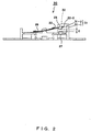
- Fig. 3 is a perspective view of the thermal protector according to the second preferred embodiment. Also in this figure, configurations of constituent elements other than a partition wall are similar to those of the thermal protector 15 shown in Fig. 1. Therefore, only constituent elements required for explanation are denoted with reference numerals and shown in Fig. 3.
- a partition wall 35 is formed to enclose the whole of the main body 34 of the thermal protector except for external circuit connection terminals 17 and 18. Also in this case, the height of the partition wall 35 is formed to be higher than a gap g (see Fig. 1(c) or 2) when contacts are released, and to have a height which does not exceed the heights of the movable contact 23 and the end 22-2 of the movable plate 22.
- the thermal protector 33 within an appliance is arranged in an orientation oblique or orthogonal to the direction of a wind velocity, effects of preventing a problem that an arc between released contacts when a high electric current is interrupted is carried away by a high wind velocity, and damages a conductive member in the periphery of the contacts is maintained. Accordingly, the degree of freedom of designing an appliance where the thermal protector is arranged inside can be enhanced, which offers a convenience.
- a partition wall having a height in a range which does not confine an arc excessively is arranged at least in the neighborhood of contacts in a thermal protector as a temperature over-rise preventing device included in recent hair dryer, electronic fan heater, popcorn machine, etc., which use a high electric current. Accordingly, an arc between the contacts can be prevented from coming out of the contacts by being carried way by a wind, and from being spattered to a conductive member in the neighborhood of the contacts even when a high electric current is interrupted, or in a wind of a high rate of flow.
- the whole of the main body of the thermal protector is enclosed by a partition wall, so that a configuration where a wind is difficult to directly flow between contacts in any direction is implemented. Therefore, even if the thermal protector within an appliance is arranged in an orientation oblique or orthogonal to the direction of a wind velocity, effects of preventing an arc between released contacts when a high electric current is interrupted from being carried away by a high wind velocity, and from damaging a conductive member in the periphery of the contacts is maintained. Accordingly, the degree of freedom of designing an appliance where the thermal protector is arranged inside is enhanced, which offers a convenience.
- the thermal protector according to the present invention is arranged in a desired position in an appliance that uses a high electric current or a wind of a high rate of flow, no problems are caused by the melting, the damage, the short circuit, etc. of a conductive member, and the reliability of the appliance is high. Therefore, the present invention is applicable to all of industries using a hot-air generating device, such as a hair dryer, an electronic fan heater, a popcorn machine, etc., which utilize a high electric current or a wind of a high rate of flow, and require high reliability.
- a hot-air generating device such as a hair dryer, an electronic fan heater, a popcorn machine, etc.
Landscapes
- Physics & Mathematics (AREA)
- Thermal Sciences (AREA)
- Thermally Actuated Switches (AREA)
Applications Claiming Priority (3)
| Application Number | Priority Date | Filing Date | Title |
|---|---|---|---|
| JP2001059063 | 2001-03-02 | ||
| JP2001059063A JP4338332B2 (ja) | 2001-03-02 | 2001-03-02 | サーマルプロテクタ |
| PCT/JP2002/001878 WO2002071431A1 (en) | 2001-03-02 | 2002-02-28 | Thermal protector |
Publications (3)
| Publication Number | Publication Date |
|---|---|
| EP1372174A1 true EP1372174A1 (de) | 2003-12-17 |
| EP1372174A4 EP1372174A4 (de) | 2005-03-09 |
| EP1372174B1 EP1372174B1 (de) | 2012-07-18 |
Family
ID=18918686
Family Applications (1)
| Application Number | Title | Priority Date | Filing Date |
|---|---|---|---|
| EP02701650A Expired - Lifetime EP1372174B1 (de) | 2001-03-02 | 2002-02-28 | Thermische schutzeinrichtung |
Country Status (5)
| Country | Link |
|---|---|
| US (1) | US7026907B2 (de) |
| EP (1) | EP1372174B1 (de) |
| JP (1) | JP4338332B2 (de) |
| CN (1) | CN1269163C (de) |
| WO (1) | WO2002071431A1 (de) |
Cited By (2)
| Publication number | Priority date | Publication date | Assignee | Title |
|---|---|---|---|---|
| ES2327302A1 (es) * | 2006-03-31 | 2009-10-27 | Bsh Electrodomesticos España S.A. | Dispositivo para electrodomestico. |
| CN101034643B (zh) * | 2006-03-07 | 2011-05-25 | 打矢恒温器株式会社 | 恒温器 |
Families Citing this family (17)
| Publication number | Priority date | Publication date | Assignee | Title |
|---|---|---|---|---|
| US7304561B2 (en) * | 2004-10-12 | 2007-12-04 | Sensata Technologies, Inc. | Motor overload protector |
| CN101069254B (zh) * | 2005-02-02 | 2010-05-26 | 打矢恒温器株式会社 | 恒温器 |
| US7760066B2 (en) * | 2005-10-14 | 2010-07-20 | Uchiya Thermostat Co. Ltd. | Temperature switch |
| DE112007002532B4 (de) * | 2006-10-30 | 2014-09-18 | Uchiya Thermostat Co., Ltd. | Temperaturschalter |
| US7800477B1 (en) * | 2007-03-20 | 2010-09-21 | Thermtrol Corporation | Thermal protector |
| DE102008048554B3 (de) * | 2008-09-16 | 2010-02-04 | Hofsaess, Marcel P. | Temperaturabhängiger Schalter |
| US7808361B1 (en) * | 2008-11-25 | 2010-10-05 | Tsung Mou Yu | Dual protection device for circuit |
| DE112009004858B4 (de) * | 2009-03-12 | 2022-08-11 | Uchiya Thermostat Co., Ltd. | Schaltung mit einem selbstschaltenden Wärme-Schutzschalter und einem Strombegrenzungs-element für einen elektrischen Schaltkreis, sowie einen entsprechenden elektrischen Schaltkreis |
| US9000880B2 (en) * | 2009-03-12 | 2015-04-07 | Uchiya Thermostat Co., Ltd. | Thermal protector |
| US9472363B2 (en) | 2009-03-12 | 2016-10-18 | Uchiya Thermostat Co., Ltd. | Thermal protector |
| WO2011055577A1 (ja) | 2009-11-04 | 2011-05-12 | ウチヤ・サーモスタット株式会社 | 三端子付きサーマルスイッチを接続した電気回路及びその接続方法 |
| US9159985B2 (en) * | 2011-05-27 | 2015-10-13 | Ostuka Techno Corporation | Circuit breaker and battery pack including the same |
| WO2016125343A1 (ja) * | 2015-02-04 | 2016-08-11 | ウチヤ・サーモスタット株式会社 | サーマルプロテクタ |
| CN106463302B (zh) * | 2015-04-28 | 2018-06-08 | 打矢恒温器株式会社 | 热保护器 |
| CN208093449U (zh) * | 2018-04-08 | 2018-11-13 | 厦门赛尔特电子有限公司 | 一种带热保护的温度控制器 |
| CN209729814U (zh) * | 2019-05-08 | 2019-12-03 | 佛山市高明欧一电子制造有限公司 | 一种背包式断电复位限温器 |
| WO2022009862A1 (ja) * | 2020-07-06 | 2022-01-13 | ウチヤ・サーモスタット株式会社 | サーマルプロテクタ |
Family Cites Families (15)
| Publication number | Priority date | Publication date | Assignee | Title |
|---|---|---|---|---|
| BE435491A (de) * | 1938-08-27 | |||
| US3240908A (en) * | 1960-12-19 | 1966-03-15 | Texas Instruments Inc | Thermostatic switches |
| JPS4120515Y1 (de) * | 1966-06-28 | 1966-10-04 | ||
| JPS5871307U (ja) * | 1981-11-11 | 1983-05-14 | 九州日立マクセル株式会社 | ヘア−ドライヤ−用サ−モスタツト |
| JPH06251674A (ja) | 1993-02-23 | 1994-09-09 | Matsushita Electric Works Ltd | サーモスイッチ |
| WO1995004364A2 (en) | 1993-08-03 | 1995-02-09 | Otter Controls Limited | Improvements relating to electric switches |
| JPH07282701A (ja) * | 1994-04-05 | 1995-10-27 | Texas Instr Japan Ltd | 自己保持型保護装置 |
| JP2791384B2 (ja) * | 1994-12-09 | 1998-08-27 | ウチヤ・サーモスタット株式会社 | サーモスタット |
| JP2899550B2 (ja) * | 1995-08-30 | 1999-06-02 | ウチヤ・サーモスタット株式会社 | サーマルプロテクタ |
| JPH09120763A (ja) | 1995-10-26 | 1997-05-06 | Matsushita Electric Works Ltd | 風検知スイッチと、これを用いた温風器及びヘアードライヤー |
| JP2000311574A (ja) * | 1999-04-28 | 2000-11-07 | Texas Instr Japan Ltd | 電気装置 |
| US6559752B1 (en) * | 1999-05-24 | 2003-05-06 | Frank J. Sienkiewicz | Creepless snap acting bimetallic switch having flexible contact members |
| US6498559B1 (en) * | 2000-05-24 | 2002-12-24 | Christopher Cornell | Creepless snap acting bimetallic switch having step adjacent its bimetallic element |
| US6633222B2 (en) * | 2000-08-08 | 2003-10-14 | Furukawa Precision Engineering Co., Ltd. | Battery breaker |
| JP4471479B2 (ja) * | 2000-10-13 | 2010-06-02 | ウチヤ・サーモスタット株式会社 | サーマルプロテクタ |
-
2001
- 2001-03-02 JP JP2001059063A patent/JP4338332B2/ja not_active Expired - Lifetime
-
2002
- 2002-02-28 US US10/469,715 patent/US7026907B2/en not_active Expired - Lifetime
- 2002-02-28 WO PCT/JP2002/001878 patent/WO2002071431A1/ja not_active Ceased
- 2002-02-28 CN CN02805743.0A patent/CN1269163C/zh not_active Expired - Lifetime
- 2002-02-28 EP EP02701650A patent/EP1372174B1/de not_active Expired - Lifetime
Cited By (3)
| Publication number | Priority date | Publication date | Assignee | Title |
|---|---|---|---|---|
| CN101034643B (zh) * | 2006-03-07 | 2011-05-25 | 打矢恒温器株式会社 | 恒温器 |
| ES2327302A1 (es) * | 2006-03-31 | 2009-10-27 | Bsh Electrodomesticos España S.A. | Dispositivo para electrodomestico. |
| ES2327302B1 (es) * | 2006-03-31 | 2010-07-21 | Bsh Electrodomesticos España S.A. | Dispositivo para electrodomesticos. |
Also Published As
| Publication number | Publication date |
|---|---|
| JP2002260507A (ja) | 2002-09-13 |
| US20040075526A1 (en) | 2004-04-22 |
| EP1372174A4 (de) | 2005-03-09 |
| WO2002071431A1 (en) | 2002-09-12 |
| US7026907B2 (en) | 2006-04-11 |
| CN1503980A (zh) | 2004-06-09 |
| CN1269163C (zh) | 2006-08-09 |
| EP1372174B1 (de) | 2012-07-18 |
| JP4338332B2 (ja) | 2009-10-07 |
Similar Documents
| Publication | Publication Date | Title |
|---|---|---|
| US7026907B2 (en) | Thermal protector | |
| CN101529546B (zh) | 热保护器 | |
| JPH0834075B2 (ja) | サーマルスイッチ | |
| JPH11339614A (ja) | 密封ケ―ス入りの開路型サ―モスタット | |
| JP2005129471A (ja) | サーマルプロテクタ | |
| JP2000243199A (ja) | 密閉ケース開放保持サーモスタット | |
| KR20000062162A (ko) | 모터 보호 장치 | |
| JP2005243626A (ja) | 電気スイッチに関する改良 | |
| US5684447A (en) | Failsafe bimetallic reed having bimetal with fusible link for a circuit protector | |
| US10510502B2 (en) | Thermal protector | |
| KR100799136B1 (ko) | 크리프 동작형 소형 자동 온도 조절 전기 스위치 및 이와 함께 이용되는 자동 온도 조절 부재 | |
| US5898555A (en) | Overload protector with overcurrent and over temperature protection | |
| JP7406279B2 (ja) | モータプロテクタ | |
| EP1605486B1 (de) | Störschutz für elektrische Geräte | |
| JPWO2015177925A1 (ja) | 熱応動開閉器 | |
| JPS61288334A (ja) | 熱安全器 | |
| JP6413203B2 (ja) | 熱応動開閉器 | |
| KR200397437Y1 (ko) | 세라믹소체 파괴시 진행성 방지를 위한 안전장치 | |
| KR102894988B1 (ko) | 과부하 보호 장치 | |
| KR102775211B1 (ko) | 재투입 타입 전선 퓨즈 | |
| JP3849387B2 (ja) | サーマルプロテクタ | |
| KR100562170B1 (ko) | 세라믹소체 파괴시 진행성 방지를 위한 전자장치 | |
| KR101243712B1 (ko) | 과부하 보호장치 | |
| JP6644237B2 (ja) | 熱応動開閉器 | |
| KR100784143B1 (ko) | 과전류 차단기 및 이를 이용한 플러그와 멀티 탭 |
Legal Events
| Date | Code | Title | Description |
|---|---|---|---|
| PUAI | Public reference made under article 153(3) epc to a published international application that has entered the european phase |
Free format text: ORIGINAL CODE: 0009012 |
|
| 17P | Request for examination filed |
Effective date: 20030909 |
|
| AK | Designated contracting states |
Kind code of ref document: A1 Designated state(s): DE GB |
|
| A4 | Supplementary search report drawn up and despatched |
Effective date: 20050121 |
|
| 17Q | First examination report despatched |
Effective date: 20090528 |
|
| GRAP | Despatch of communication of intention to grant a patent |
Free format text: ORIGINAL CODE: EPIDOSNIGR1 |
|
| RIN1 | Information on inventor provided before grant (corrected) |
Inventor name: TAKEDA, HIDEAKI |
|
| GRAS | Grant fee paid |
Free format text: ORIGINAL CODE: EPIDOSNIGR3 |
|
| GRAA | (expected) grant |
Free format text: ORIGINAL CODE: 0009210 |
|
| AK | Designated contracting states |
Kind code of ref document: B1 Designated state(s): DE |
|
| REG | Reference to a national code |
Ref country code: DE Ref legal event code: R096 Ref document number: 60243334 Country of ref document: DE Effective date: 20120913 |
|
| PLBE | No opposition filed within time limit |
Free format text: ORIGINAL CODE: 0009261 |
|
| STAA | Information on the status of an ep patent application or granted ep patent |
Free format text: STATUS: NO OPPOSITION FILED WITHIN TIME LIMIT |
|
| 26N | No opposition filed |
Effective date: 20130419 |
|
| REG | Reference to a national code |
Ref country code: DE Ref legal event code: R097 Ref document number: 60243334 Country of ref document: DE Effective date: 20130419 |
|
| REG | Reference to a national code |
Ref country code: DE Ref legal event code: R082 Ref document number: 60243334 Country of ref document: DE Representative=s name: KLUNKER IP PATENTANWAELTE PARTG MBB, DE |
|
| PGFP | Annual fee paid to national office [announced via postgrant information from national office to epo] |
Ref country code: DE Payment date: 20210323 Year of fee payment: 20 |
|
| REG | Reference to a national code |
Ref country code: DE Ref legal event code: R071 Ref document number: 60243334 Country of ref document: DE |