EP1375183A2 - Vorrichtung zum Übertragen von Flüssigkeiten, Verfahren zum Übertragen von Flüssigkeiten und Verfahren zur Überwachung der Restflüssigkeitsmenge in der Vorrichtung zum Übertragen von Flüssigkeiten - Google Patents
Vorrichtung zum Übertragen von Flüssigkeiten, Verfahren zum Übertragen von Flüssigkeiten und Verfahren zur Überwachung der Restflüssigkeitsmenge in der Vorrichtung zum Übertragen von Flüssigkeiten Download PDFInfo
- Publication number
- EP1375183A2 EP1375183A2 EP03014650A EP03014650A EP1375183A2 EP 1375183 A2 EP1375183 A2 EP 1375183A2 EP 03014650 A EP03014650 A EP 03014650A EP 03014650 A EP03014650 A EP 03014650A EP 1375183 A2 EP1375183 A2 EP 1375183A2
- Authority
- EP
- European Patent Office
- Prior art keywords
- liquid
- transfer
- transfer device
- accumulating
- liquid transfer
- Prior art date
- Legal status (The legal status is an assumption and is not a legal conclusion. Google has not performed a legal analysis and makes no representation as to the accuracy of the status listed.)
- Granted
Links
- 239000007788 liquid Substances 0.000 title claims abstract description 1138
- 238000012546 transfer Methods 0.000 title claims abstract description 481
- 238000000034 method Methods 0.000 title claims description 42
- 238000012544 monitoring process Methods 0.000 title claims description 11
- 230000013011 mating Effects 0.000 claims abstract description 21
- 230000002708 enhancing effect Effects 0.000 claims abstract description 17
- 238000007639 printing Methods 0.000 claims description 54
- 239000011148 porous material Substances 0.000 claims description 37
- 238000009825 accumulation Methods 0.000 claims description 21
- 230000005540 biological transmission Effects 0.000 claims description 17
- 238000000638 solvent extraction Methods 0.000 claims description 15
- 239000012298 atmosphere Substances 0.000 claims description 8
- 230000000994 depressogenic effect Effects 0.000 claims description 7
- 238000010030 laminating Methods 0.000 claims description 6
- 238000012545 processing Methods 0.000 claims description 3
- 230000000881 depressing effect Effects 0.000 claims 1
- 239000010408 film Substances 0.000 description 189
- 239000010410 layer Substances 0.000 description 143
- 239000000976 ink Substances 0.000 description 40
- 238000012986 modification Methods 0.000 description 38
- 230000004048 modification Effects 0.000 description 38
- 239000005022 packaging material Substances 0.000 description 25
- 239000003086 colorant Substances 0.000 description 22
- 238000010276 construction Methods 0.000 description 20
- VYPSYNLAJGMNEJ-UHFFFAOYSA-N Silicium dioxide Chemical compound O=[Si]=O VYPSYNLAJGMNEJ-UHFFFAOYSA-N 0.000 description 18
- 239000010419 fine particle Substances 0.000 description 18
- -1 acryl Chemical group 0.000 description 16
- 230000001965 increasing effect Effects 0.000 description 16
- 238000007641 inkjet printing Methods 0.000 description 16
- 239000000463 material Substances 0.000 description 14
- 239000000853 adhesive Substances 0.000 description 12
- 230000001070 adhesive effect Effects 0.000 description 12
- 238000004519 manufacturing process Methods 0.000 description 11
- 238000012360 testing method Methods 0.000 description 10
- 230000005489 elastic deformation Effects 0.000 description 9
- 238000002474 experimental method Methods 0.000 description 9
- 230000008569 process Effects 0.000 description 9
- 230000002829 reductive effect Effects 0.000 description 9
- 239000002250 absorbent Substances 0.000 description 8
- 230000002745 absorbent Effects 0.000 description 8
- PNEYBMLMFCGWSK-UHFFFAOYSA-N aluminium oxide Inorganic materials [O-2].[O-2].[O-2].[Al+3].[Al+3] PNEYBMLMFCGWSK-UHFFFAOYSA-N 0.000 description 8
- 229920005989 resin Polymers 0.000 description 8
- 239000011347 resin Substances 0.000 description 8
- 239000000377 silicon dioxide Substances 0.000 description 8
- XLYOFNOQVPJJNP-UHFFFAOYSA-N water Substances O XLYOFNOQVPJJNP-UHFFFAOYSA-N 0.000 description 8
- 239000004743 Polypropylene Substances 0.000 description 7
- 238000013461 design Methods 0.000 description 7
- 239000011521 glass Substances 0.000 description 7
- TWNQGVIAIRXVLR-UHFFFAOYSA-N oxo(oxoalumanyloxy)alumane Chemical compound O=[Al]O[Al]=O TWNQGVIAIRXVLR-UHFFFAOYSA-N 0.000 description 7
- 229920000126 latex Polymers 0.000 description 6
- 239000004816 latex Substances 0.000 description 6
- 229920001343 polytetrafluoroethylene Polymers 0.000 description 6
- 239000004810 polytetrafluoroethylene Substances 0.000 description 6
- 230000002093 peripheral effect Effects 0.000 description 5
- CBENFWSGALASAD-UHFFFAOYSA-N Ozone Chemical compound [O-][O+]=O CBENFWSGALASAD-UHFFFAOYSA-N 0.000 description 4
- TZCXTZWJZNENPQ-UHFFFAOYSA-L barium sulfate Chemical compound [Ba+2].[O-]S([O-])(=O)=O TZCXTZWJZNENPQ-UHFFFAOYSA-L 0.000 description 4
- 239000002585 base Substances 0.000 description 4
- 239000011230 binding agent Substances 0.000 description 4
- 238000000151 deposition Methods 0.000 description 4
- 239000007789 gas Substances 0.000 description 4
- 239000003921 oil Substances 0.000 description 4
- 230000035699 permeability Effects 0.000 description 4
- 229920001155 polypropylene Polymers 0.000 description 4
- 229910052709 silver Inorganic materials 0.000 description 4
- 239000004332 silver Substances 0.000 description 4
- 239000002356 single layer Substances 0.000 description 4
- 239000011800 void material Substances 0.000 description 4
- MWUXSHHQAYIFBG-UHFFFAOYSA-N Nitric oxide Chemical compound O=[N] MWUXSHHQAYIFBG-UHFFFAOYSA-N 0.000 description 3
- 238000005452 bending Methods 0.000 description 3
- 230000015572 biosynthetic process Effects 0.000 description 3
- 230000015556 catabolic process Effects 0.000 description 3
- 239000003795 chemical substances by application Substances 0.000 description 3
- 229920001577 copolymer Polymers 0.000 description 3
- 238000006731 degradation reaction Methods 0.000 description 3
- 235000014113 dietary fatty acids Nutrition 0.000 description 3
- 238000007599 discharging Methods 0.000 description 3
- 230000000694 effects Effects 0.000 description 3
- 238000005516 engineering process Methods 0.000 description 3
- 239000000194 fatty acid Substances 0.000 description 3
- 229930195729 fatty acid Natural products 0.000 description 3
- 239000000835 fiber Substances 0.000 description 3
- 238000000465 moulding Methods 0.000 description 3
- 238000003892 spreading Methods 0.000 description 3
- 230000007480 spreading Effects 0.000 description 3
- 238000010998 test method Methods 0.000 description 3
- VTYYLEPIZMXCLO-UHFFFAOYSA-L Calcium carbonate Chemical compound [Ca+2].[O-]C([O-])=O VTYYLEPIZMXCLO-UHFFFAOYSA-L 0.000 description 2
- WSFSSNUMVMOOMR-UHFFFAOYSA-N Formaldehyde Chemical compound O=C WSFSSNUMVMOOMR-UHFFFAOYSA-N 0.000 description 2
- XUIMIQQOPSSXEZ-UHFFFAOYSA-N Silicon Chemical compound [Si] XUIMIQQOPSSXEZ-UHFFFAOYSA-N 0.000 description 2
- PPBRXRYQALVLMV-UHFFFAOYSA-N Styrene Chemical compound C=CC1=CC=CC=C1 PPBRXRYQALVLMV-UHFFFAOYSA-N 0.000 description 2
- XLOMVQKBTHCTTD-UHFFFAOYSA-N Zinc monoxide Chemical compound [Zn]=O XLOMVQKBTHCTTD-UHFFFAOYSA-N 0.000 description 2
- 239000000654 additive Substances 0.000 description 2
- 230000000996 additive effect Effects 0.000 description 2
- XAGFODPZIPBFFR-UHFFFAOYSA-N aluminium Chemical compound [Al] XAGFODPZIPBFFR-UHFFFAOYSA-N 0.000 description 2
- 229910052782 aluminium Inorganic materials 0.000 description 2
- VSCWAEJMTAWNJL-UHFFFAOYSA-K aluminium trichloride Chemical compound Cl[Al](Cl)Cl VSCWAEJMTAWNJL-UHFFFAOYSA-K 0.000 description 2
- VXAUWWUXCIMFIM-UHFFFAOYSA-M aluminum;oxygen(2-);hydroxide Chemical compound [OH-].[O-2].[Al+3] VXAUWWUXCIMFIM-UHFFFAOYSA-M 0.000 description 2
- ANBBXQWFNXMHLD-UHFFFAOYSA-N aluminum;sodium;oxygen(2-) Chemical compound [O-2].[O-2].[Na+].[Al+3] ANBBXQWFNXMHLD-UHFFFAOYSA-N 0.000 description 2
- 239000007864 aqueous solution Substances 0.000 description 2
- QVQLCTNNEUAWMS-UHFFFAOYSA-N barium oxide Chemical compound [Ba]=O QVQLCTNNEUAWMS-UHFFFAOYSA-N 0.000 description 2
- 229910001864 baryta Inorganic materials 0.000 description 2
- 239000011248 coating agent Substances 0.000 description 2
- 238000000576 coating method Methods 0.000 description 2
- 239000008119 colloidal silica Substances 0.000 description 2
- 238000004891 communication Methods 0.000 description 2
- 238000005520 cutting process Methods 0.000 description 2
- 230000003247 decreasing effect Effects 0.000 description 2
- 230000008021 deposition Effects 0.000 description 2
- 239000011888 foil Substances 0.000 description 2
- 238000010438 heat treatment Methods 0.000 description 2
- 230000007062 hydrolysis Effects 0.000 description 2
- 238000006460 hydrolysis reaction Methods 0.000 description 2
- 239000001023 inorganic pigment Substances 0.000 description 2
- 239000000314 lubricant Substances 0.000 description 2
- 230000009965 odorless effect Effects 0.000 description 2
- 239000012788 optical film Substances 0.000 description 2
- 239000002245 particle Substances 0.000 description 2
- 239000000049 pigment Substances 0.000 description 2
- 229920000139 polyethylene terephthalate Polymers 0.000 description 2
- 239000005020 polyethylene terephthalate Substances 0.000 description 2
- 229920000642 polymer Polymers 0.000 description 2
- 230000001681 protective effect Effects 0.000 description 2
- 229910052710 silicon Inorganic materials 0.000 description 2
- 239000010703 silicon Substances 0.000 description 2
- 238000004513 sizing Methods 0.000 description 2
- 229910001388 sodium aluminate Inorganic materials 0.000 description 2
- GGCZERPQGJTIQP-UHFFFAOYSA-N sodium;9,10-dioxoanthracene-2-sulfonic acid Chemical compound [Na+].C1=CC=C2C(=O)C3=CC(S(=O)(=O)O)=CC=C3C(=O)C2=C1 GGCZERPQGJTIQP-UHFFFAOYSA-N 0.000 description 2
- 239000002904 solvent Substances 0.000 description 2
- 238000003860 storage Methods 0.000 description 2
- 238000009827 uniform distribution Methods 0.000 description 2
- PHMFOWQZOHAHQY-UHFFFAOYSA-N 2-ethyl-2-(hydroxymethyl)propane-1,3-diol;16-methylheptadecanoic acid Chemical compound CCC(CO)(CO)CO.CC(C)CCCCCCCCCCCCCCC(O)=O.CC(C)CCCCCCCCCCCCCCC(O)=O.CC(C)CCCCCCCCCCCCCCC(O)=O PHMFOWQZOHAHQY-UHFFFAOYSA-N 0.000 description 1
- 229920002134 Carboxymethyl cellulose Polymers 0.000 description 1
- VGGSQFUCUMXWEO-UHFFFAOYSA-N Ethene Chemical compound C=C VGGSQFUCUMXWEO-UHFFFAOYSA-N 0.000 description 1
- 239000005977 Ethylene Substances 0.000 description 1
- 108010010803 Gelatin Proteins 0.000 description 1
- 229920000084 Gum arabic Polymers 0.000 description 1
- 239000004354 Hydroxyethyl cellulose Substances 0.000 description 1
- 229920000663 Hydroxyethyl cellulose Polymers 0.000 description 1
- 239000004372 Polyvinyl alcohol Substances 0.000 description 1
- 241000978776 Senegalia senegal Species 0.000 description 1
- PMZURENOXWZQFD-UHFFFAOYSA-L Sodium Sulfate Chemical compound [Na+].[Na+].[O-]S([O-])(=O)=O PMZURENOXWZQFD-UHFFFAOYSA-L 0.000 description 1
- 229920002472 Starch Polymers 0.000 description 1
- 239000002174 Styrene-butadiene Substances 0.000 description 1
- GWEVSGVZZGPLCZ-UHFFFAOYSA-N Titan oxide Chemical compound O=[Ti]=O GWEVSGVZZGPLCZ-UHFFFAOYSA-N 0.000 description 1
- XSQUKJJJFZCRTK-UHFFFAOYSA-N Urea Chemical compound NC(N)=O XSQUKJJJFZCRTK-UHFFFAOYSA-N 0.000 description 1
- 208000027418 Wounds and injury Diseases 0.000 description 1
- 239000000205 acacia gum Substances 0.000 description 1
- 235000010489 acacia gum Nutrition 0.000 description 1
- 230000002411 adverse Effects 0.000 description 1
- 239000002518 antifoaming agent Substances 0.000 description 1
- 238000013459 approach Methods 0.000 description 1
- 230000001174 ascending effect Effects 0.000 description 1
- 239000007844 bleaching agent Substances 0.000 description 1
- 230000000740 bleeding effect Effects 0.000 description 1
- 229910000019 calcium carbonate Inorganic materials 0.000 description 1
- 239000004202 carbamide Substances 0.000 description 1
- 239000001768 carboxy methyl cellulose Substances 0.000 description 1
- 235000010948 carboxy methyl cellulose Nutrition 0.000 description 1
- 239000008112 carboxymethyl-cellulose Substances 0.000 description 1
- 239000001913 cellulose Substances 0.000 description 1
- 229920002678 cellulose Polymers 0.000 description 1
- 239000004927 clay Substances 0.000 description 1
- 229910052570 clay Inorganic materials 0.000 description 1
- 230000000295 complement effect Effects 0.000 description 1
- 230000006835 compression Effects 0.000 description 1
- 238000007906 compression Methods 0.000 description 1
- 239000013078 crystal Substances 0.000 description 1
- 230000006378 damage Effects 0.000 description 1
- 238000011161 development Methods 0.000 description 1
- GDVKFRBCXAPAQJ-UHFFFAOYSA-A dialuminum;hexamagnesium;carbonate;hexadecahydroxide Chemical compound [OH-].[OH-].[OH-].[OH-].[OH-].[OH-].[OH-].[OH-].[OH-].[OH-].[OH-].[OH-].[OH-].[OH-].[OH-].[OH-].[Mg+2].[Mg+2].[Mg+2].[Mg+2].[Mg+2].[Mg+2].[Al+3].[Al+3].[O-]C([O-])=O GDVKFRBCXAPAQJ-UHFFFAOYSA-A 0.000 description 1
- 238000002845 discoloration Methods 0.000 description 1
- 239000002270 dispersing agent Substances 0.000 description 1
- 239000006185 dispersion Substances 0.000 description 1
- 238000009826 distribution Methods 0.000 description 1
- TXKMVPPZCYKFAC-UHFFFAOYSA-N disulfur monoxide Inorganic materials O=S=S TXKMVPPZCYKFAC-UHFFFAOYSA-N 0.000 description 1
- 238000001035 drying Methods 0.000 description 1
- 239000005038 ethylene vinyl acetate Substances 0.000 description 1
- 238000011156 evaluation Methods 0.000 description 1
- 125000000524 functional group Chemical group 0.000 description 1
- 229920000159 gelatin Polymers 0.000 description 1
- 239000008273 gelatin Substances 0.000 description 1
- 235000019322 gelatine Nutrition 0.000 description 1
- 235000011852 gelatine desserts Nutrition 0.000 description 1
- 230000005484 gravity Effects 0.000 description 1
- 229960001545 hydrotalcite Drugs 0.000 description 1
- 229910001701 hydrotalcite Inorganic materials 0.000 description 1
- 235000019447 hydroxyethyl cellulose Nutrition 0.000 description 1
- 239000001866 hydroxypropyl methyl cellulose Substances 0.000 description 1
- 229920003088 hydroxypropyl methyl cellulose Polymers 0.000 description 1
- 235000010979 hydroxypropyl methyl cellulose Nutrition 0.000 description 1
- UFVKGYZPFZQRLF-UHFFFAOYSA-N hydroxypropyl methyl cellulose Chemical compound OC1C(O)C(OC)OC(CO)C1OC1C(O)C(O)C(OC2C(C(O)C(OC3C(C(O)C(O)C(CO)O3)O)C(CO)O2)O)C(CO)O1 UFVKGYZPFZQRLF-UHFFFAOYSA-N 0.000 description 1
- 230000006872 improvement Effects 0.000 description 1
- 239000003112 inhibitor Substances 0.000 description 1
- 230000000977 initiatory effect Effects 0.000 description 1
- 208000014674 injury Diseases 0.000 description 1
- 238000005304 joining Methods 0.000 description 1
- NLYAJNPCOHFWQQ-UHFFFAOYSA-N kaolin Chemical compound O.O.O=[Al]O[Si](=O)O[Si](=O)O[Al]=O NLYAJNPCOHFWQQ-UHFFFAOYSA-N 0.000 description 1
- 239000002932 luster Substances 0.000 description 1
- FPYJFEHAWHCUMM-UHFFFAOYSA-N maleic anhydride Chemical compound O=C1OC(=O)C=C1 FPYJFEHAWHCUMM-UHFFFAOYSA-N 0.000 description 1
- 238000005259 measurement Methods 0.000 description 1
- 230000007246 mechanism Effects 0.000 description 1
- 125000002496 methyl group Chemical group [H]C([H])([H])* 0.000 description 1
- 239000000203 mixture Substances 0.000 description 1
- 230000003287 optical effect Effects 0.000 description 1
- 239000012860 organic pigment Substances 0.000 description 1
- 239000007800 oxidant agent Substances 0.000 description 1
- 230000001590 oxidative effect Effects 0.000 description 1
- 239000003002 pH adjusting agent Substances 0.000 description 1
- WXZMFSXDPGVJKK-UHFFFAOYSA-N pentaerythritol Chemical compound OCC(CO)(CO)CO WXZMFSXDPGVJKK-UHFFFAOYSA-N 0.000 description 1
- 229920001200 poly(ethylene-vinyl acetate) Polymers 0.000 description 1
- 229920002451 polyvinyl alcohol Polymers 0.000 description 1
- 229920000036 polyvinylpyrrolidone Polymers 0.000 description 1
- 239000001267 polyvinylpyrrolidone Substances 0.000 description 1
- 235000013855 polyvinylpyrrolidone Nutrition 0.000 description 1
- 230000000644 propagated effect Effects 0.000 description 1
- 230000009467 reduction Effects 0.000 description 1
- 230000000717 retained effect Effects 0.000 description 1
- 150000003376 silicon Chemical class 0.000 description 1
- 229910052938 sodium sulfate Inorganic materials 0.000 description 1
- 235000011152 sodium sulphate Nutrition 0.000 description 1
- 239000007787 solid Substances 0.000 description 1
- 239000008107 starch Substances 0.000 description 1
- 235000019698 starch Nutrition 0.000 description 1
- 229920003048 styrene butadiene rubber Polymers 0.000 description 1
- XTQHKBHJIVJGKJ-UHFFFAOYSA-N sulfur monoxide Chemical compound S=O XTQHKBHJIVJGKJ-UHFFFAOYSA-N 0.000 description 1
- 229910052815 sulfur oxide Inorganic materials 0.000 description 1
- 239000004094 surface-active agent Substances 0.000 description 1
- 239000000454 talc Substances 0.000 description 1
- 229910052623 talc Inorganic materials 0.000 description 1
- 239000002562 thickening agent Substances 0.000 description 1
- OGIDPMRJRNCKJF-UHFFFAOYSA-N titanium oxide Inorganic materials [Ti]=O OGIDPMRJRNCKJF-UHFFFAOYSA-N 0.000 description 1
- 239000012780 transparent material Substances 0.000 description 1
- 239000006097 ultraviolet radiation absorber Substances 0.000 description 1
- 125000000391 vinyl group Chemical group [H]C([*])=C([H])[H] 0.000 description 1
- 229920002554 vinyl polymer Polymers 0.000 description 1
- 230000000007 visual effect Effects 0.000 description 1
- 229920003169 water-soluble polymer Polymers 0.000 description 1
- 239000011787 zinc oxide Substances 0.000 description 1
Images

















Classifications
-
- B—PERFORMING OPERATIONS; TRANSPORTING
- B41—PRINTING; LINING MACHINES; TYPEWRITERS; STAMPS
- B41J—TYPEWRITERS; SELECTIVE PRINTING MECHANISMS, i.e. MECHANISMS PRINTING OTHERWISE THAN FROM A FORME; CORRECTION OF TYPOGRAPHICAL ERRORS
- B41J29/00—Details of, or accessories for, typewriters or selective printing mechanisms not otherwise provided for
-
- B—PERFORMING OPERATIONS; TRANSPORTING
- B05—SPRAYING OR ATOMISING IN GENERAL; APPLYING FLUENT MATERIALS TO SURFACES, IN GENERAL
- B05C—APPARATUS FOR APPLYING FLUENT MATERIALS TO SURFACES, IN GENERAL
- B05C11/00—Component parts, details or accessories not specifically provided for in groups B05C1/00 - B05C9/00
- B05C11/10—Storage, supply or control of liquid or other fluent material; Recovery of excess liquid or other fluent material
- B05C11/105—Storage, supply or control of liquid or other fluent material; Recovery of excess liquid or other fluent material by capillary action, e.g. using wicks
-
- B—PERFORMING OPERATIONS; TRANSPORTING
- B41—PRINTING; LINING MACHINES; TYPEWRITERS; STAMPS
- B41M—PRINTING, DUPLICATING, MARKING, OR COPYING PROCESSES; COLOUR PRINTING
- B41M7/00—After-treatment of prints, e.g. heating, irradiating, setting of the ink, protection of the printed stock
- B41M7/0027—After-treatment of prints, e.g. heating, irradiating, setting of the ink, protection of the printed stock using protective coatings or layers by lamination or by fusion of the coatings or layers
Definitions
- the present invention relates generally to a liquid transfer device and a liquid transfer method. More particularly, the invention relates to a liquid transfer device and a liquid transfer method for transferring or applying a liquid, such as an image protecting liquid or the like to a printing surface of a printing medium printed by an ink-jet printing apparatus. The invention further relates to a liquid remaining amount monitoring method for such a liquid transfer device.
- an ink-jet printing apparatus has mainly been used for printing texts of characters or the like on a printing medium, such as paper or the like.
- the ink-jet printing apparatus is also used for formation of photographic image.
- range of application of the ink-jet printing apparatus has been extended to field of photographic printing, graphic art and so on. Aside from spreading of such ink-jet printing apparatus, it has been becoming important problem how to improve keeping quality and to expand life of the image formed by such ink-jet printing apparatus.
- a printed product printed by depositing dye-type ink on an appropriate medium has good color developing ability, but is lower in durability and keeping quality of image.
- a printed product printed by pigment-type ink is superior in keeping quality but is inferior in color development ability and abrasion-resistance.
- Japanese Patent Application Laid-Open No. 9-048180 discloses a treatment for a measure for bleeding of image due to deposition of water droplets on the printed product or degradation of image due to irradiation of ultraviolet ray.
- a printing medium provided with water resistance or light fastness against ultraviolet ray by the treatment disclosed in the above-identified publication it has been found that fatigue by moisture and/or minor component gas, such as ozone, nitrogen oxide, sulfur oxide or the like contained in the air occurs, as certain time elapsed. It has been demanded to establish a technology to improve durability of the image with maintaining image texture of the image (raw image) formed by the ink-jet printing apparatus and so on as early as possible.
- such technology has to be convenient to be easily handled by a user.
- Another object of the present invention is to provide a liquid holding apparatus which can hold a liquid without local concentration over entire liquid holding portion in the liquid holding apparatus for the liquid transfer device and so on.
- a further object of the present invention is to provide a liquid transfer device which can improve durability of the image with maintaining image texture and can improve usability.
- a still further object of the present invention is to provide a liquid transfer device which can appropriately hold the liquid within the liquid transfer device without causing leakage of the liquid.
- the inventors have researched and developed an apparatus and method which permits directly viewing a raw image without interposing a transparent layer, such as glass, film or the like on a printing medium, can maintain image texture for a long period and can transfer an appropriate amount of liquid without depositing the liquid on hand.
- a liquid transfer device transferring liquid for enhancing durability of an image on a printed surface of a printed product printed with ink, comprising:
- the restricting portion may be formed from a porous film formed with fine pores.
- the liquid transfer device may further comprise a holding member for receiving and holding the liquid transfer member.
- the liquid accumulating portion may be formed from a sheet form member having uniform density.
- the holding member may include a surface supporting frame formed with an opening portion exposing the restricting portion and a dish shaped receptacle member having a flange mating with a lower surface of the surface supporting frame, the liquid transfer member may be received within a receptacle space defined by the receptacle member and the surface supporting frame.
- the liquid accumulating portion may be formed from a sheet form member having different density in thickness direction thereof.
- the liquid accumulating portion may be formed from a sheet form member provided with treatment for continuously varying a density in thickness direction with a predetermined gradient.
- the liquid accumulating portion may be formed by laminating a plurality of sheet form members having different densities.
- Capillary forces of the liquid accumulating portion, the porous film and the printed surface of the printed product may be set for establishing a relationship
- Densities of respective sheet form members forming the liquid accumulating portion may be set for producing greater capillary force at closer position to the transfer surface.
- the liquid accumulating portion may be formed with a first layer and a second layer having different densities, the first layer may be located at a position more distant from the transfer surface than the second layer, and the first layer may have greater density than the second layer.
- the liquid transfer device may further comprise a holding member receiving the liquid transfer member, the holding member may include a surface supporting frame having an opening portion, into which the first layer covered with the restricting portion is inserted, and a dish shaped receptacle member having a flange mating with a lower surface of the surface supporting frame, the second layer may be received with a receptacle space defined by the receptacle member and the surface supporting frame and the first layer covered by the restricting portion projects upwardly from a surface of the surface supporting frame, and a surface of the restricting portion may form a transfer zone.
- the holding member may include a surface supporting frame having an opening portion, into which the first layer covered with the restricting portion is inserted, and a dish shaped receptacle member having a flange mating with a lower surface of the surface supporting frame, the second layer may be received with a receptacle space defined by the receptacle member and the surface supporting frame and the first layer covered by the restricting portion projects upwardly from a
- the first layer and the second layer may be formed from a fibrous body or a foamed sponge body, a density of the first layer may be in a range of 0.05 to 0.5 g/cc, and a density of the second layer may be in a range of 0.01 to 0.2 g/cc.
- the porous film may have a thickness of 10 to 200 ⁇ m, and a diameter of fine pore may be 0.1 to 3 ⁇ m.
- the liquid transfer member may have a normally flat transfer surface, when the printed product is mounted and urged onto the transfer surface, the liquid accumulating portion may be elastically deformed corresponding to a curved shape of the printed surface of the printed product so that the curved printed surface and the transfer surface are contacted over entire area.
- Stripe form grooves may be formed on a bottom surface of the liquid accumulating portion.
- a liquid holding device holding a liquid by capillary force comprising:
- each of the plurality of liquid holding members may be determined in size so as to hold the liquid over substantially entire region of the liquid holding member irrespective of attitude of the liquid holding device.
- a liquid transfer device transferring liquid to an object to be transferred the liquid, comprising:
- each of the plurality of liquid accumulating members may be set at a size for accumulating the liquid over substantially entire region of the liquid accumulating member irrespective of attitude of the liquid transfer device.
- the plurality of liquid accumulating members may be dividedly arranged so that liquids accumulated in each of the plurality of liquid accumulating members are communicated with each other as depressed through the transfer film.
- the plurality of liquid accumulating members may be separated from each other by partitioning walls.
- Thicknesses of the partitioning walls may be in a range of 0.1 mm to 1 mm.
- the plurality of liquid accumulating members may be processed at an accuracy so that a length of burr possibly formed during processing becomes less than the thickness of the partitioning wall.
- a plurality of holding members or liquid accumulating members holding the liquid by capillary force can hold a liquid amount greater than the liquid amount to be held by total volume of the plurality of holding member or the liquid accumulating members at a predetermined attitude of the liquid holding device or the liquid accumulating device, irrespective of the attitude of the liquid holding device or the liquid accumulating device. Therefore, even when respective holding members or the liquid accumulating members hold the liquid entirely for holding the liquid in the amount to be held or in necessary amount for transfer, leakage of the liquid from the liquid holding device or the liquid accumulating device can be prevented even when the attitude of the liquid holding device or the liquid accumulating device is orienting the longitudinal direction in vertical direction, for example.
- such a liquid transfer device is preferably constructed to perform liquid transfer for a plurality of times for various sizes of printing medium as set forth above.
- amount of the liquid to be received in the absorbing body has a given limit. Associating with this, there is a given limit even for number of times of transfer of the liquid for the object to be transferred the liquid.
- a liquid transfer device which transfers a predetermined liquid to an object to be transferred the liquid, may comprise:
- liquid transfer device view condition of the colored member through the absorbing body is varied depending upon transmission coefficient of the absorbing body variable according to increase of number of times of liquid transfer. Therefore, user may perform liquid transfer operation for the object to be transferred the liquid with monitoring the liquid remaining amount in the absorbing body.
- the liquid transfer device it becomes possible to enhance durability of the image with maintaining image texture of the image by certainly and uniformly transferring the liquid to the object, significantly improving workability in the liquid transfer operation.
- the absorbing body may be supported by an essentially transparent receptacle member, and the colored member may be visible through the receptacle member and the absorbing body.
- the absorbing body may include a first absorbing body having a first density and a second absorbing body having a second density lower than the first density, and the colored member may be visible through the second absorbing body.
- An embedding height of the colored member in the absorbing body may be determined so as to detect lacking of liquid remaining amount in the absorbing body from view condition of the colored member at a timing where a predetermined times of liquid transfer is completed.
- the absorbing body may include a first absorbing body and a second absorbing body, and thickness of at least one of the first absorbing body and the second absorbing body may be determined so as to detect lacking of remaining liquid amount in the absorbing body from view condition of the colored member at a timing where a predetermined times of liquid transfer is completed.
- the colored member may have a plurality of holes permitting flow of the liquid.
- the colored member may have an external dimension of at least 5 mm square.
- the colored member may be embedded in the absorbing body at a position not overlapping with the transfer zone.
- the colored member may be embedded in the absorbing body at a position overlapping with the transfer zone.
- the colored member may be embedded in the absorbing body in a tilted state relative to the surface of the porous body so that lacking of liquid remaining amount in the absorbing body can be perceived from view condition of the colored member at a time of completion of transfer for a predetermined number of times.
- the colored member can be seen through the porous body and the absorbing body.
- the absorbing body may include a first absorbing body having a first density and a second absorbing body having a second density lower than the first density, thickness of at least one of the first absorbing body and the second absorbing body may be determined so that lacking of liquid remaining amount in the absorbing body can be perceived from viewing condition of the colored member at a time of completion of transfer for a predetermined number of times.
- a liquid remaining amount monitoring method of a liquid transfer device having a porous body having a transfer zone contacting an object to be transferred liquid and an absorbing body arranged in contact with the porous body and capable of absorbing and holding a predetermined liquid, and transferring the liquid to the object arranged in the transfer zone, wherein the method comprising the steps of:
- the colored member in a tilted state with respect to the surface of the porous member.
- the liquid accumulating member may be determined a dimension so that an amount of the liquid to be held without causing leakage even upon exposing to atmosphere becomes the initial accumulation amount.
- the liquid accumulating member may be determined a dimension so that an amount of the liquid to be held without causing leakage even when the primary surface is oriented in vertical direction, becomes the initial accumulation amount.
- the liquid accumulating member may be determined a dimension in a direction of the primary surface so that the primary surface becomes larger than the transfer surface.
- the liquid accumulating member may have a layer having relatively high density and in which the transfer surface is positioned, and a layer having relatively low density and in which the primary surface is arranged, the liquid accumulating member may be determined a dimension so that a sum of the amounts of liquid to be held without causing leakage in each of the layers becomes the initial accumulation amount.
- a dimension of the layer having relatively low density in a direction of the primary surface may be determined so that the primary surface of the layer having relatively low density is larger than a bottom surface of the layer having relatively high density where the transfer surface is positioned and mating with the primary surface.
- a porous film formed with fine pores restrictingly supplying the liquid exuding from the liquid accumulating member, may be arranged on the transfer surface.
- the initial accumulation amount may be determined with taking an amount of liquid to be held by the porous film without causing leakage, and the dimension of the liquid accumulating member may be determined corresponding to the initial accumulation amount.
- Grooves for smoothly moving the liquid to the position corresponding to the transfer surface may be provided in the liquid accumulating member.
- any liquid leakage can be prevented at any attitude of the liquid transfer device in handling or storing in non-use state.
- a word “transfer” used for description of the present invention includes print, impress or apply a liquid for protection on a surface of a printed product by contacting a printed product to be applied protecting treatment and a liquid transfer member of a liquid transfer device.
- a word “transfer zone (transfer surface)” represents either a surface per se of a porous member exemplified in the following embodiments or a surface of a desired impregnated member.
- the member is an absorbent member of which a liquid impregnating amount is restricted by a restricting member including at least one layer of film, for restricting a transfer amount of liquid between the printed product to be protected and a liquid storage portion, and is an absorbent body.
- a restricting member including at least one layer of film, for restricting a transfer amount of liquid between the printed product to be protected and a liquid storage portion
- an absorbent body such as thin fibrous body (including paper) sponge or a laminated structural body or the like, which can absorb a necessary amount of liquid for one or more printed product for applying liquid thereon.
- a "printed product" to be used in the present invention is one formed with an image by applying inks containing coloring agents on a printing medium having a porous layer as an ink receptacle layer. Then, in the present invention, in such a printed product, liquid, such as silicon oils, fatty acid esters or the like is impregnated. Accordingly, it is desirable that the printing medium forming the printed product is those not causing so-called strike through.
- it is preferably a printing medium which performs printing by at least absorbing coloring agents, such as dye, pigment or the like in fine particles forming a porous structure in an ink receptacle layer provided on a support body.
- the printing medium of such structure is particularly preferred for ink-jet printing.
- Such printing medium for ink-jet printing is preferably a so-called absorbent type which absorbs ink with void formed in the ink receptacle layer on the support body.
- the ink receptacle layer of absorbent type is primarily formed with fine particle and is formed into porous layer containing binder and/or other additive, as required.
- fine particle one or more kind selected among silica, clay, talc, calcium carbonate, porcelain clay, aluminum oxide, such as alumina, alumina hydrate or the like, diatom earth, titanium oxide, hydrotalcite, inorganic pigment such as zinc oxide or organic pigment, such as urea formalin resin, ethylene resin, styrene resin or the like, may be used.
- Preferred binder to be used may be water soluble polymer or latex.
- dispersing agent thickening agent, pH adjuster, lubricant, fluidized modifying agent.
- surface active agent anti-foaming agent , mold lubricant, fluorescent bleach, ultraviolet absorber, oxidant inhibitor and so on may be used.
- Particularly preferred printing medium is those formed with the ink receptacle layer primarily consisted of fine particles having average particle size smaller than or equal to 10 ⁇ m, and more preferably smaller than or equal to 1 ⁇ m.
- Particularly preferred fine particles are fine particles of silica or aluminum oxide or the like.
- Preferred fine particles of silica are silica fine particles typified by colloidal silica. While colloidal silica per se is available from a market, particularly preferred is those disclosed in Japanese Patent No. 2803134, Japanese Patent No. 2881847, for example.
- Preferred fine particles of aluminum oxide may be fine particles of alumina hydrate.
- One of such alumina type pigment may be alumina hydrate expressed by the following formula; Al 2 O 3-n (OH) 2n • mH 2 O
- n represents any one of integer of 1, 2 and 3
- m represents a value in a range of 0 to 10, and preferably 0 to 5.
- m and n cannot be 0 simultaneously.
- mH 2 O represents even desporptive water phase not to be involved with formation of mH 2 O crystal grating. Therefore, m may be a value of integer or non-integer.
- m can reach the value of 0.
- alumina hydrate it is typically preferred those produced by hydrolysis of aluminum alcoxide or hydrolysis of sodium aluminate disclosed in U. S. Patent No. 4,242,271 and U. S. Patent No.
- fine particles of aluminum oxide, silica or the like are particularly effective is as follow. Namely, it has been found that the coloring agent to be absorbed by fine particles of aluminum oxide or silica should cause significant tenebrescence of the coloring agent due to gases of NO x , SO x , ozone or the like. However, these particles can draw gases so that such gases may present in the vicinity of the coloring agent to easily cause tenebrescence of the coloring agent.
- the print ing medium for ink-jet printing using fine particles of aluminum oxide or fine particles of silica is superior in affinity, absorbability, fixing ability with protecting liquid, and can attain transparency, luster and fixing ability of the coloring agent in the printing liquid, such as dye or the like, as required for realizing photograph quality as set forth above. Therefore, such printing medium is optimal for use in the present invention.
- a mixture ratio of the fine particles and binder of the printing medium is preferably in a range of 1:1 to 100:1 by weight.
- a preferred content of fine particles of aluminum oxide or fine particles of silica in the ink receptacle layer is greater than or equal to 50 Wt%, more preferably greater than or equal to 70 Wt%, further preferably greater than or equal to 80 Wt%, and most preferably smaller than or equal to 99 Wt%.
- a coating amount of the ink receptacle layer is preferably greater than or equal to 10 g/m 2 as converted into dried solid component in order to enhance impregnating ability of image fastness enhancing agent, and most preferably 10 to 30 g/m 2 .
- the support (base paper) of the printing medium there is no particular constraint, and any supports may be used as long as the ink receptacle layer containing the foregoing fine particles can be formed and having sufficient stiffness so as to be fed by a feeding mechanism of the ink-jet printer or the like.
- a sheet of paper provided with appropriate sizing at least on the surface to be formed the ink receptacle layer, one having high density porous layer (so called baryta layer) formed by coating inorganic pigment, such as barium sulfate or the like, and so on, on the fibrous support (such as baryta paper) may be preferably used.
- the liquid for protecting the printed product used in the present invention may be those not influencing the fixed image not dissolving the coloring agent deposited on the porous layer of the printing medium, being non-volatile, and protecting the coloring agent upon filling void in the porous layer for enhancing durability of the image.
- the liquid not adversely influencing for color tone of the image 'and being transparent and colorless capable of enhancing quality of the image is superior in general applicability-
- colored liquid may also be used.
- the odorless liquid is superior in general applicability, it may also be possible to add some perfumery in a range not affecting to the image for discharging aroma matching with the image.
- the protecting liquid for example, at least one selected among fatty acid ester such as pentaerythritol, silicon oil, modified silicon fluorinated oil may be used. Particularly, for pore distribution and pore size of the printing medium, one dispersed and homogenized is preferred and entirely covering a presenting region (two-dimensional, three-dimensional) of the printed base material.
- Such liquid for protecting image is held in a liquid transfer device according to the present invention, which will be discussed later.
- the liquid has an appropriate permeability into the porous layer, on which the coloring agent of the printed image is fixed.
- the liquid has viscosity in a range of about 10 to 400 cp (0.01 to 0.4 Pa ⁇ s).
- Figs. 1A to 1C show conditions where the liquid for protecting set forth above is applied to the printed product M having base paper (a support body) M1, a reflection layer M2 and the ink receptacle layer M3.
- Fig. 1A shows a condition before transferring the liquid
- Fig. 1B shows a condition immediately after transfer of the liquid in which excessively transferred liquid is present on a surface of the printed product and optically recognized
- Fig. 1C shows a condition 2 to 5 minutes after transfer of the liquid in which the excessively transferred liquid is absorbed into the base paper M1
- Figs. 2A and 2B are sections showing conditions before and after transfer of an appropriate amount of liquid on the printed product M by the liquid transfer device according to the present invention.
- the coloring agent CM die in the embodiment herewith discussed
- an appropriate amount of liquid L is applied as shown in Fig. 2B.
- the liquid L is uniformly propagated over the entire ink receptacle layer M3 to certainly hold the coloring agent CM, and the extra amount of liquid may not overflow from the ink receptacle layer M3 to maintain in a condition not perceived even optically.
- a transfer amount may be effected by density of a printed image or a drying time after printing. The above results are in the case of thoroughly dried states.
- Fig. 3A is a perspective view showing a construction of the first embodiment of the liquid transfer device
- Fig. 3B is a section of the liquid transfer device shown in Fig. 3A
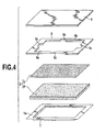
- Fig. 4 is an exploded perspective view of the liquid transfer device of Fig. 3A.
- the first embodiment of the liquid transfer device 1 is constructed with a liquid transfer member 2 accumulating a liquid for enhancing durability of a printed product and transferring the liquid on a printed surface of the printed product, and a holding member 3 holding a circumference of the liquid transfer member 2.
- the liquid transfer member 2 is constituted by a quadrangular sheet form liquid accumulating member (liquid accumulating portion) 4, which is formed from a fibrous body or a foamed sponge having a predetermined elasticity, and a quadrangular porous film 5 tightly fitted on one surface (front surface/outer surface side) of the liquid accumulating member 4 for covering the latter.
- the liquid accumulating member 4 has substantially uniform thickness, elasticity and density over the entire region and has a single layer structure.
- a fibrous body is selected in consideration of shelf life.
- PP polypropylene
- PET polyethylene terephthalate
- PET polyethylene terephthalate
- a density of the fibrous body determines large and small of liquid holding ability (capillary force) and elastic force depending upon high and low. Large and small of the liquid holding ability and elastic force determine large and small of discharge amount of the liquid contained therein and number of times of liquid to be transferred, as shown in table 2. Density of the fibers has to be appropriately selected depending upon number of times of transferring and exuding ability of the liquid and so forth.
- the fibrous body of the size 178 mm (longitudinal) x 130 mm (lateral) x 4.0 mm (thick), and practically applicable density of the fibrous body of this size is in a range of 0.06 g/cc to 0.4 g/cc.
- the density of the fibrous body is 0.2 g/cc.
- the porous film 5 is formed from PTFE (polytetrafluoroethylene) film formed with pores permitting the liquid to pass, over the entire surface.
- PTFE polytetrafluoroethylene
- it is desirable that pore size formed in the porous film 5 is in a range of 0.1 to 3 ⁇ m, preferably 0.1 to 1 ⁇ m, and thickness is 50 to 200 ⁇ m. It should be noted that when pore size of the porous film 5 is larger, liquid permeability becomes higher.
- the pore size in this context means that used in the filter industry, and can be determined by means of test methods such as Bubble Point or Mean Flow Pore Test. Strictly speaking, results of these methods show different values respectively. However, they have similar tendencies and show almost same values.
- the value of the pore size shown in the present invention is measured by means of Bubble Point method.
- the thickness of the porous film 5 is important for avoiding occurrence of irregularity in transfer. Namely, when the porous film 5 is excessively thin, the porous film becomes less elastic to easily cause deformation to easily cause transfer irregularity upon transfer to the printing medium. Conversely, when the porous film is excessively thick, elasticity becomes excessively high to be hardly deformed to cause difficulty in flexibly contacting over the entire area upon transferring to the printing medium having bent or irregularity in shape. Even in this case, irregularity in transfer is easily caused. In the experiments, optimal transfer condition can be obtained without irregularity in transfer when the thickness of the porous film 5 is set at 80 ⁇ m.
- the holding member 3 holding the foregoing liquid accumulating member 2 is constructed with a quadrangular surface supporting frame 6 bonded on the surface of the porous film 5 by an adhesive 60, a container form receptacle member 7 for receiving the liquid accumulating member 2, a lid 8 for covering an opening portion of the surface supporting frame 6 for opening and closing, and a connecting member 9 connecting the lid 8 and the receptacle member 7.
- the surface supporting frame 6 is formed with a plate member of PET having appropriate rigidity and thickness.
- the surface supporting frame 6 projects outwardly from the porous film 5, and is formed with a quadrangular opening portion 6a for exposing the porous film 5 housed inside of the surface supporting frame 6.
- thickness of the surface supporting frame 6 is set at 0.75 mm.
- the receptacle member 7 is formed into a container (dish) shape by vacuum molding of semi-transparent PET sheet having thickness of about 0.2 mm.
- a frame (flange) form connecting portion 7a projected along the opening portion is welded on the lower surface of the surface supporting frame.
- the liquid transfer member 2 is received within a receptacle space defined by the receptacle member 7 and the surface supporting frame 6 in a condition impossible to dropout and exposing the surface of the liquid accumulating member 2 through the opening portion of the surface supporting frame 6.
- the reference numeral 6b shows an end face forming the opening portion 6a of the surface supporting frame 6
- the reference numeral 6c shows a recessed portion formed in each end face 6b for facilitating taking out of the printing medium inserted within the opening portion 6a.
- the adhesive 60 is applied on a bottom surface of the surface support frame 6 along the opening portion 6a.
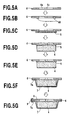
- the surface supporting frame 6 is bonded on the surface of the porous film 5 (having dimension of 168 mm x 126 mm x 0.08 mm) (see Figs. 5A, 5B and 5C).
- the porous film 5 fixed on the surface supporting frame 6 is fitted on the surface of the liquid accumulating member (having dimension of 178 mm x 130 mm x 4.0 mm) 4. Then, these three members are housed within the receptacle member 7.
- the bottom surface of the surface supporting frame 6 and a mating portion 7a of the receptacle member 7 are fitted and joined together by heat seal.
- a non-heat sealed portion is formed to serve as liquid pouring opening.
- a liquid supply tube connected to a predetermined liquid supply source is inserted into the liquid pouring opening to pour the liquid to the liquid accumulating member 4.
- the liquid supply tube is drawn out, and in place, a suction tube connected to a predetermined vacuum source is inserted to discharge inside air.
- the suction tube is drawn out to close the liquid pouring opening by heat seal.
- the lid 8 is connected to the receptacle member 7 by the connecting member 9 which is welded on the lid 8 at one end and welded on the lower surface of the mating portion 7a of the receptacle member 7 at the other end (see Fig. 5G).
- the connecting member 9 which is welded on the lid 8 at one end and welded on the lower surface of the mating portion 7a of the receptacle member 7 at the other end (see Fig. 5G).
- Fig. 6A is a perspective view showing a construction of the first modification of the first embodiment of the liquid transfer device
- Fig. 6B is a cross section of the liquid transfer device shown in Fig. 6A
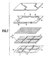
- Fig. 7 is an exploded perspective view of the liquid transfer device shown in Figs. 6A and 6B.
- the first modification of the first embodiment of the liquid transfer device 1 is constructed with the liquid transfer member 2 accumulating the liquid for enhancing durability of the printed product and transferring the liquid on the printed surface of the printed product, and the holding member 3 holding the circumferential edge of the liquid transfer member 2.
- the liquid transfer member 2 is formed with a plurality of (six in the shown embodiment) quadrangular sheet form liquid accumulating members 4 formed from fibrous body or foamed sponge having predetermined elasticity, and the quadrangular porous film 5 tightly fitted and covering on one surface (front surface/outer surface side) of the liquid accumulating members 4.
- a plurality of liquid accumulating members 4 (also referred to as liquid holding members in the disclosure) have substantially equal thickness, elasticity and density with each other.
- a plurality of separated liquid accumulating members 4 with integral porous film 5 it becomes possible to hold the liquid with uniformly distributing the liquid over entire area of the porous film 5 which will be discussed later in detail.
- uniform distribution of the liquid becomes possible.
- the liquid may be supplied uniformly over the entire area of the printed region upon transferring the liquid to the printed product through the porous film 5.
- the first modification of the shown embodiment of the liquid accumulating member 4 is formed by selecting fibrous body in consideration of shelf life.
- fibrous body PP (polypropylene), PET (polyethylenterephthalate) and the like is applicable.
- PET polyethylenterephthalate
- a density of the fibrous body determines large and small of liquid holding ability (capillary force) and elastic force depending upon high and low. Large and small of the liquid holding ability and elastic force determine large and small of discharge amount of the liquid contained therein and number of times of liquid transfer, as shown in table 2. Density of the fibers has to be appropriately selected depending upon number of times of transferring and exuding ability of the liquid and so forth.
- the fibrous body of the size 178 mm (longitudinal) x 130 mm (lateral) x 4.0 mm (thick), and practically applicable density of the fibrous body of this size is in a range of 0.06 g/cc to 0.4 g/cc.
- the density of the fibrous body is 0.2 g/cc.
- the porous film 5 is formed from PTFE (polytetrafluoroethylene) film formed with pores permitting the liquid to pass, over the entire surface.
- PTFE polytetrafluoroethylene
- it is desirable that pore size formed in the porous film 5 is in a range of 0.1 to 3 ⁇ m, preferably 0.1 to 1 ⁇ m, and thickness is 50 to 200 ⁇ m. It should be noted that when pore size of the porous film 5 is larger, liquid permeability becomes higher.
- the pore size in this context means that used in the filter industry, and can be determined by means of test methods such as Bubble Point or Mean Flow Pore Test. Strictly speaking, results of these methods show different values respectively. However, they have similar tendencies and show almost same values.
- the value of the pore size shown in the present invention is measured by means of Bubble Point method.
- the thickness of the porous film 5 is important for avoiding occurrence of irregularity in transfer. Namely, when the porous film 5 is excessively thin, the porous film becomes less elastic to easily cause deformation to easily cause transfer irregularity upon transfer to the printing medium. Conversely, when the porous film is excessively thick, elasticity becomes excessively high to be hardly deformed to cause difficulty in flexibly contacting over the entire area upon transferring to the printing medium having bent or irregularity in shape. Even in this case, irregularity in transfer is easily caused. In the experiments, an optimal transfer condition can be obtained without irregularity in transfer when the thickness of the porous film 5 is set at 80 ⁇ m.
- the holding member 3 holding the foregoing liquid accumulating member 2 is constructed with a quadrangular surface supporting frame 6 bonded on the surface of the porous film 5 by an adhesive 60, a container form receptacle member 7 for receiving the liquid accumulating member 2, a lid 8 for closing an opening portion of the surface supporting frame 6 for opening and closing, and a connecting member 9 connecting the lid 8 and the receptacle member 7.
- the surface supporting frame 6 is formed with the plate member of PET having appropriate rigidity and thickness, projecting outwardly from the porous film 5, and is formed with a quadrangular opening portion 6a for exposing the porous film 6 housed inside of the surface supporting frame 6. It should be noted that thickness of the surface supporting frame 6 is set at 0.75 mm.
- the receptacle member 7 is formed into a container shape byvacuummolding of semi-transparent PET sheet having thickness of about 0.2 mm.
- a frame form connecting portion 7a projected along the opening portion is welded on the lower surface of the surface supporting frame 6.
- the reference numeral 6b denotes an end face forming the opening portion 6a of the surface supporting frame 6
- the reference numeral 6c denotes a recessed portion formed in each end face 6b for facilitating taking out of the printing medium inserted within the opening portion 6a.
- each partitioning wall 7b defining a plurality of receptacle chambers for receiving respective liquid accumulating members 4 are provided.
- a thickness of each partitioning wall 7b is 0.5 mm and height thereof is 1.5 mm.
- the liquid held in respective liquid accumulating members 4 are communicated with each other so that the liquid can be exuded uniformly over the entire porous film 5 without forming non-exuding portion despite of presence of gaps defined between respective liquid accumulating members received separately.
- it can prevent occurrence of irregularity in liquid transfer to the printed product due to failure of dispersion of the liquid over the surface of the porous film 5 upon transferring.
- finishing accuracy of the liquid accumulating members is determined. Namely, when burr formed upon formation of the liquid accumulating members by processing the fibrous body, extends over the space between the liquid accumulating members to cause communication of the separated liquid accumulating members, such burr may cause communication of liquid even in non-transferring state and thereby possibly cause local concentration of the liquid. Therefore, particularly depending upon the thickness of the partitioning wall 7b determined so that the liquid does not communicate during non-transferring state and the liquid is communicated by depression via the porous film or transfer film upon transferring, the finishing accuracy is determined so that a length of burr is less than or equal to the thickness of the partitioning wall even though burr is produced.
- the adhesive 60 is applied on a portion of the bottom surface of the surface support frame 6 around the opening portion.
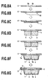
- the surface supporting frame 6 is bonded on the surface of the porous film 5 (having dimension of 168 mm x 126 mm x 0.08 mm) (see Figs. 8A, 8B and 8C).
- the porous film 5 fixed on the surface supporting frame 6 is fitted on the surface of the separated liquid accumulating member (each having dimension of one sixth of 178 mm x 130 mm x 4.0 mm) 4.
- these three members are housed within respective receptacle chambers defined by the partitioning walls 7b in the receptacle member 7.
- the bottom surface of the surface supporting frame 6 and a mating portion 7a of the receptacle member 7 are fitted and joined together by heat seal.
- the liquid is supplied from the liquid supply tube connected to the predetermined liquid supply source.
- supplied liquid penetrates into respective liquid accumulating members via the porous film 5 and held therein.
- a method for filling the liquid in the liquid accumulating members 4 is no limited to the method of the foregoing example.
- the liquid may be directly filled in respective liquid accumulating members 4.
- the lid 8 is connected to the receptacle member 7 by the connecting member 9 a which is welded on one edge of the lid 8 and welded on the lower surface of the mating portion 7a of the receptacle member 7 (see Fig. 8G).
- the connecting member 9 a which is welded on one edge of the lid 8 and welded on the lower surface of the mating portion 7a of the receptacle member 7 (see Fig. 8G).
- Fig. 9A is a perspective view showing a construction of the second modification of the first embodiment of the liquid transfer device
- Fig. 9B is a cross section of the liquid transfer device shown in Fig. 9A
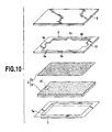
- Fig. 10 is an exploded perspective view of the liquid transfer device shown in Figs. 9A and 9B.
- the liquid transfer device 1 illustrated in Figs. 9A to 11G is constructed with the liquid transfer member 2 accumulating a liquid for enhancing durability of a printed product and transferring the liquid on the printed surface of the printed product, and the holding member 3 holding a circumferential edge of the liquid transfer member 2.
- the liquid transfer member 2 is formed with a quadrangular sheet form liquid accumulating member (absorbent body) 4 formed from a fibrous body or a foamed sponge having a predetermined elasticity, and a quadrangular porous film (porous body) 5 tightly fitted on one surface (front surface/outer surface side) of the liquid accumulating member for covering the latter.
- the liquid accumulating member 4 has substantially uniform thickness, elasticity and density over the entire region and has a single layer structure.
- a fibrous body is selected as the liquid accumulating member 4 in consideration of shelf life.
- PP polypropylene
- PET polyethyleneterephthalate
- PET polyethyleneterephthalate
- a density of the fibrous body determines large and small of liquid holding ability (capillary force) and elastic force depending upon high and low. Large and small of the liquid holding ability and elastic force determine large and small of discharge amount of the liquid contained therein and number of times of liquid transfer, as shown in table 2. Density of the fibers has to be appropriately selected depending upon number of times of transferring and exuding ability of the liquid and so forth.
- the fibrous body of the size 178 mm (longitudinal) x 130 mm (lateral) x 4.0 mm (thick), and practically applicable density of the fibrous body of this size is in a range of 0.06 g/cc to 0.4 g/cc.
- the density of the fibrous body is 0.2 g/cc.
- the porous film 5 is formed from PTFE film formed with pores permitting the liquid to pass, over the entire surface.
- pore size formed in the porous film 5 is in a range of 0.1 to 3 ⁇ m, preferably 0.1 to 1 ⁇ m, and thickness is 50 to 200 ⁇ m. It should be noted that when pore size of the porous film 5 is larger, liquid permeability becomes higher.
- the pore size in this context means that used in the filter industry, and can be determined by means of test methods such as Bubble Point or Mean Flow Pore Test. Strictly speaking, results of these methods show different values respectively. However, they have similar tendencies and show almost same values.
- the value of the pore size shown in the present invention is measured by means of Bubble Point method.
- the thickness of the porous film 5 is important for avoiding occurrence of irregularity in transfer. Namely, when the porous film 5 is excessively thin, the porous film becomes less elastic to easily cause deformation to easily cause transfer irregularity upon transfer to the printing medium. Conversely, when the porous film is excessively thick, elasticity becomes excessively high to be hardly deformed to cause difficulty in flexibly contacting over the entire area upon transferring to the printing medium having bent or irregularity in shape. Even in this case, irregularity in transfer is easily caused. In the experiments, optimal transfer condition can be obtained without irregularity in transfer when the thickness of the porous film 5 is set at 80 ⁇ m. It should be noted that a relationship of liquid holding ability of the porous film 5, the liquid accumulating member 4 and the printed product is printed product > porous film > liquid accumulating member.
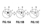
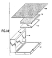
- a colored member (remaining amount detecting body) 90 for monitoring remaining amount of the liquid is embedded in the liquid accumulating member 4, as shown in Fig. 9.
- the colored member 90 is buried in the liquid accumulating member 4 by forming cut line in the latter.
- the colored member 90 is formed from a polypropylene mesh sheet, a sheet formed with apertures, a sheet with slits and so on, colored into a predetermined color, for example.
- the coloring agent has external dimension of 15 mm in a longitudinal direction, 5 mm in a lateral direction and 0.2 mm of thickness.
- the colored member 90 As set forth above, by forming the colored member 90 to have at least 5 mm x 5 mm of external dimension, visibility of the colored member 90 can be ensured with avoiding the presence thereof to serve as hindrance for flow of the liquid in the liquid accumulating member 4. On the other hand, by forming the colored member 90 from a thin sheet having a plurality of apertures permitting flow of the liquid, presence of the colored member 90 does not interfere flow of the liquid in the liquid accumulating member 4. It should be noted that, in the shown embodiment, as a color to be provided for the colored member 90, green is selected. However, the color of the colored member 90 can be selected arbitrary as long as visibility can be ensured.
- the holding member 3 holding the foregoing liquid accumulating member 2 is constructed with the quadrangular surface supporting frame 6 bonded on the surface of the porous film 5 by an adhesive 60, the receptacle member (support) 7 serving as a container for receiving the liquid accumulating member 2, a lid 8 for covering an opening portion of the surface supporting frame 6 for opening and closing, and a connecting member 9 connecting the lid 8 and the receptacle member 7.
- the surface supporting frame 6 is formed from the plate member of PET having an appropriate rigidity and thickness, projecting outwardly from the porous film 5, and is formed with a quadrangular opening portion 6a for exposing the porous film 6 housed therein. It should be noted that thickness of the surface supporting frame 6 is set at 0.75 mm in the shown embodiment.
- the receptacle member 7 is formed into a container shape by vacuum molding of substantially transparent (semi-transparent) PET sheet having thickness of about 0.2 mm. A frame (flange) form connecting portion 7 projected along the opening portion is welded on the lower surface of the surface supporting frame.
- the liquid transfer member 2 is received within a receptacle space defined by the receptacle member 7 and the surface supporting frame 6 in a condition impossible to dropout and exposing the surface of the liquid accumulating member 2 through the opening portion of the surface supporting frame 6.
- the reference numeral 6b denotes the end face forming the opening portion 6a of the surface supporting frame 6
- the reference numeral 6c denotes a recessed portion formed in each end face 6b for facilitating taking out of the printing medium inserted within the opening portion 6a.
- the adhesive 60 is applied on the bottom surface of the surface support frame 6 along the opening portion 6a.
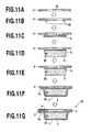
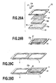
- the surface supporting frame 6 is bonded on the surface of the porous film 5 (having dimension of 168 mm x 126 mm x 0.08 mm) (see Figs. 11A, 11B and 11C).
- the porous film 5 fixed on the surface supporting frame 6 is fitted on the surface of the liquid accumulating member (having dimension of 178 mm x 130 mm x 4.0 mm) 4 with the embedded colored member 90. Then, these three members are housed within the receptacle member 7.
- the bottom surface of the surface supporting frame 6 and a mating portion 7a of the receptacle member 7 are fitted and joined together by heat seal. At this timing, for a portion of the quadrangular mating portion 7a, a non-heat sealed portion is formed to serve as liquid pouring opening.
- a liquid supply tube connected to a predetermined liquid supply source is inserted into the liquid pouring opening to pour the liquid to the liquid accumulating member 4. Subsequently, the liquid supply tube is drawn out from the liquid pouring opening, and in place, the suction tube connected to a predetermined vacuum source is inserted to discharge inside air. At a timing reaching a given reduced pressure, the suction tube is drawn out from the liquid pouring opening to close the liquid pouring opening by heat seal. Subsequently, the lid 8 is connected to the receptacle member 7 by the connecting sheet which is welded to of the lid 8 at one end and welded on the lower surface of the mating portion 7a of the receptacle member 7 at the other end (see Fig. 11G). Thus, manufacturing of the liquid transfer device 1 is completed.
- the printed product to which is applied ink in the ink receptacle layer by an ink-jet printing apparatus or the like is prepared.
- the printed product is in a condition where solvent and moisture content contained in the ink is sufficiently evaporated. It has been confirmed that the solvent and moisture content in the liquid are completely evaporated from the ink receptacle layer after about thirty minutes from completion of printing, in normal case.
- the liquid accumulated in the liquid accumulating member 4 is drawn toward inside of the pores by the porous film 5 having greater liquid holding ability (capillary force) than the liquid accumulating member 4.
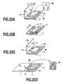
- the lid 8 is opened to mount the printed product on the surface (transfer zone) of the porous film 5 exposed from the opening portion 6a of the surface supporting frame 6 in a condition where the surface of the porous film 5 and the printed surface are contacted (see Fig. 12A).
- the lid 8 is closed to cover the printed product PM.
- a pallet S is urged onto the lid 8 and reciprocally moved for several times to tightly fitting the printed surface of the printing product PM and the porous film 5 (see Fig. 12B).
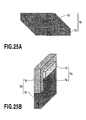
- the liquid accumulating member 4 By a depression force from the pallet S, the liquid accumulating member 4 is elastically deformed downwardly. Then, by this elastic deformation, the liquid accumulated therein is pushed out toward the surface side (printed product side). On the other hand, between the liquid accumulating member 4 and the printed surface (ink receptacle layer) of the printed product PM, the porous film 5 is present. The liquid flow toward the printing medium pushed out from the liquid accumulating member 4 is restricted by the porous film 5 so that the liquid is transferred to the printing product in just proportion. In the shown embodiment, the liquid accumulating member 4 has elasticity and the porous film 5 has flexibility. Therefore, when bending or irregularity of shape are present in the printed product PM, the entire surface of the porous film 5 is flexibly follows the surface of the printed product PM. Thus, the liquid is uniformly transferred over the entire printed surface of the printed product PM.
- the liquid accumulating members 4 are depressed as shown in Fig. 13B to push out the liquid held in the liquid accumulating members 4 to be exuded upwardly, namely to the surface of the porous film 5.
- the liquid is also exuded into the space above the partitioning walls 7b between the liquid accumulating members 4 to fill. Then, the liquid filling the space is also exuded to the surface of the porous film 5.
- appropriate deformation of the liquid accumulating members 4 is required when depressed by means of the pallet S in order to form the continuous liquid film on the surface of the porous film 5. Therefore, it is desirable that the receptacle member 7 holding the liquid accumulating members 4 may have a stiffness greater than or equal to a given value.
- the porous film 5 is present between the liquid accumulating member 4 and the printed surface (ink receptacle layer) of the printed product PM, and the porous film 5 restricts flow out of the liquid pushed out from the liquid accumulating member 4 so that the liquid may be transferred to the printed product just in proportion. Furthermore, since elasticity is provided for the liquid accumulating members 4 and flexibility is provided for the porous film 5, even if bending or irregularity of shape are present in the printed product PM, the entire surface of the porous film 5 is flexibly follows the surface of the printed product PM. Thus, the liquid is uniformly transferred over the entire printed surface of the printed product PM.
- liquid accumulating member 4 when the liquid accumulating member 4 are directly contacted with the printed product without providing the porous film 5 not as in the first embodiment, large amount of liquid pushed out from the liquid accumulating member 4 can be transferred to the printed product to possibly require wiping.
- the printing medium is removed from the porous film 5.
- the printed product PM is tightly fitted on the surface of the porous film 5 and stuck thereon by viscosity of the liquid. Therefore, upon removal from the surface of the porous film 5, a finger is hooked at an end portion of the printed product PM to peel off from the end (Fig. 12C).
- the finger may be inserted through the recessed portion 6c of the surface supporting frame 6 to easily hook the finger to the end edge of the printed product PM, permiting smooth removal of the printed product PM without causing injury of the transfer surface (see Fig. 12D).
- density of the liquid accumulating member is set at 0.2 g/cc.
- the printed product on which a photographic image was printed on a printing medium having an ink receptacle layer of pseudoboehmite using an ink-jet printer BJF870 by Canon Inc. as an ink-jet printer was used.
- a printing medium one prepared by providing a reflection layer (about 15 ⁇ m thick layer of BaSO 4 ) and a 30 ⁇ m thick ink receptacle layer formed of pseudoboehmite alumina, was used.
- printing was performed using an ink containing dye type coloring agents by the printer set forth above to obtain a printed product carrying the printed image by absorbing coloring agents in the ink receptacle layer containing alumina. In the ink receptacle layer after printing, void to absorb the liquid was remained.
- the image density was measured by a reflection type photometer RD-918 (tradename) available from MacBeth Corporation. Measured image density was expressed by OD of black portion of the image.
- ⁇ E value in silver halide photograph was measured.
- the value was about 0.2.
- ⁇ E value obtained by the first embodiment was 0.2.
- the image transferred the liquid by the first embodiment of the liquid transfer device 1 is predicted to have comparable durability as silver halide photograph under exposure to atmosphere. This indicates that the silver halide photograph causes discoloration under exposure to atmosphere in two to several tens years. and the image provided protection treatment by the first embodiment of the liquid transfer device 1 can enjoy the initial image quality over the comparable period as the silver halide photograph.
- the raw image can be enjoyed over a long period without presence of the protecting member, such as glass or film.
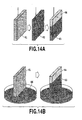
- Figs. 14A and 14B are illustrations for discussing about characteristics of the shown embodiment of the liquid accumulating member 4.
- a liquid amount to be held by the liquid holding member, such as fibrous body, forming the liquid accumulating member 4 is basically depending upon water head by capillary force. Accordingly, in the case of the liquid holding member having a given shape, the liquid amount to be held may be differentiated depending upon the attitude thereof. Figs. 14A and 14B show this condition.
- Fig. 14A shows a holding amount when the liquid holding member 61 is hanged by a wire, namely in a condition where the liquid holding member 61 is oriented in a condition where longitudinal direction is directed vertically.
- the overall liquid holding member 61 hanged by the wire is dipped in the liquid to absorb the liquid in a condition as represented by the reference numeral 62.
- the liquid holding member is divided into a liquid holding region 63 and a non liquid holding region 64.
- a height of the liquid holding region 63 is determined depending upon a water head of a capillary force which is in turn determined depending upon density of the liquid holding member 61 and other factors.
- the liquid holding member 61 can form the region not holding the liquid.
- Fig. 14B shows similar liquid holding condition, wherein the liquid holding member 61 similar to that shown in Fig. 14A is placed within a container containing liquid 66 in the attitude directing the longitudinal direction thereof in the vertical direction. Even in this case, the liquid holding member 61 should form the liquid holding region 63 and the liquid not holding region 64. The height of the liquid holding region sucking the liquid and holding becomes the same as the case of Fig. 14A.
- the liquid accumulating member 4 is, at first, not preferred for causing irregularity in the region where the liquid is transferred for presence of region not holding the liquid, upon transferring liquid. Secondly, it is not desirable to cause leakage of the liquid when the user handles or stores the liquid accumulating member in certain attitude.
- range of size of the liquid accumulating member is determined depending upon water head determined by the capillary force of the liquid accumulating member so as not to cause leakage with holding the liquid over the entire region even when the liquid accumulating member is oriented with directing the longitudinal direction in the vertical direction. Then, number of division is selected in order to realize the size of allowable range.
- transferable number of the liquid transfer device is determined depending upon the initial liquid accumulation amount of the liquid accumulating member 4.
- the liquid in the liquid accumulating member 4 may be accumulated in amount depending upon a design value of the transferable number.
- the liquid accumulating member may be formed into minimum size.
- the liquid transfer device is considered to be stored or transported in various attitudes particularly in non-use condition and so on.
- the liquid transfer device is formed by mating the bottom surface of the surface supporting frame 6 and the mating portion 7a of the receptacle member 7 and joining them by heat seal. In this portion, the liquid accumulating member 4 is sealed.
- air and liquid may flow in and out through the porous film 5 or the transfer surface and thus, the liquid accumulating member 4 is exposed to the atmosphere. Then, in some attitude of the liquid transfer device, it may be possible to cause leakage of liquid through the porous film 5 or the transfer surface.
- a liquid amount to be held by the liquid holding member, such as fibrous body, forming the liquid accumulating member 4 is basically determined depending upon the water head by the capillary force of the whole liquid holding member. Accordingly, in the liquid holding member having a given shape, the liquid amount to be held can be differentiated depending upon the attitude.
- Fig. 14A shows holding amount when the liquid holding member 61 is hanged by the wire, namely the liquid holding member 61 is oriented with directing the longitudinal direction in the vertical direction.
- the whole liquid holding member 61 hanged by the wire is dipped in the liquid to be in the condition indicated by 62.
- the region 63 100% holding the liquid and a region 64 only partly holding the liquid are formed.
- the height of the liquid holding region 63 is determined by the water head of the capillary force depending upon density of the liquid holding member 61.
- the height of the region 63 is differentiated depending upon density of material of the absorbent body. In the case of PET having density of 0.2 g/cc, the height can be 90 to 100 mm, and in the case of PET having density of 0.65 g/cc, the height can be 70 to 80 mm.
- Fig. 14B shows similar liquid holding condition, wherein the liquid holding member 61 similar to that shown in Fig. 14A is placed within a container containing liquid 66 in the attitude directing the longitudinal direction thereon in vertical direction. Even in this case, the liquid holding member 61 should form the liquid holding region 63 and the liquid not holding region 64. The height of the liquid holding region sucking the liquid and holding becomes the same as the case of Fig. 14A.
- the liquid holding member 61 may form the region 64 only partly holding the liquid so that, In the condition exposed to the atmosphere, the liquid cannot be held in the region 64 may leak.
- the liquid accumulating member 4 used in the first embodiment it is possible to be stored or handled in the attitude where the porous film 5 or transfer surface is not in horizontal condition, for example, the longitudinal direction of the liquid accumulating member 4 is directed in the vertical direction. In such a case, leakage of the liquid can be caused from the porous film 5 or transfer surface,
- size and shape of the liquid accumulating member 4 to be used in the first embodiment are determined. Namely, it is not desirable to cause leakage of the liquid at any attitude of the liquid accumulating member in handling or storing by the user.
- the liquid accumulating member to be used in the first embodiment of the present invention takes an amount of liquid to be held without causing leakage as exposed to the atmosphere instead of the maximum absorbing amount of the liquid accumulating member as initial accumulating amount. Then, dimension and shape of the liquid accumulating member is determined so that the initial accumulating amount corresponds to the design value of the transferable number. Namely, the dimension and shape of the liquid accumulating member is determined in such a manner that the amount corresponding to the design value of the transferable number becomes greater volume than that obtained in the dimension and shape to achieve the maximum accumulation volume.
- the dimension and shape are selected so that the amount of the liquid to be held without causing leakage when the porous film 5 or transfer surface is not oriented horizontally, for example, even when a primary surface or the longitudinal direction of the liquid accumulating member is oriented in the vertical direction.
- the upper surface of the first embodiment of the liquid accumulating member 4 has a dimension S2 greater than a dimension S1 of the transfer surface, on which the printed product is mounted as surrounded by the surface supporting frame 6.
- the thickness of the liquid accumulating member 4 has to be increased correspondingly.
- the liquid accumulating member 4 may appropriately cause elastic deformation in downward direction by depression force exerted through the pallet S, and by elastic deformation, the liquid accumulated in the liquid accumulating member 4 may be transferred to the printed product in appropriate amount just in proportion, excessively increasing of the thickness of the liquid accumulating member 4 is considered undesirable.
- the liquid accumulating member 4 is formed so as to adapt to the desired transferable number and not to cause leakage at any attitude by increasing dimension in the primary surface to ensure the desired thickness.
- the liquid accumulating member 4 in the first embodiment holds the liquid even outside portion (peripheral portion) of a substantially quadratic pole extending through the transfer surface and a projection of the transfer surface on the bottom surface.
- the porous film 5 may also create capillary force. Therefore, the desired accumulation amount corresponding to the design value of the transferable number and the dimension of the liquid accumulating member 4 corresponding thereto may be determined with taking the liquid holding amount into consideration when the longitudinal direction of the porous film 5 is oriented in the vertical direction.
- amount of the liquid to be stored in the liquid accumulating member 4 has a given limit. Associating with this, there is a given limit even for the transferable number of the liquid to the transfer object. It should be noted that, in the shown embodiment, for the printed product of post card size, about 130 times of liquid transfer can be performed at the maximum.
- the liquid transfer device 1 is provided with the colored member 90 which can be visually seen through the liquid accumulating member 4.
- transmission ratio or coefficient of the liquid accumulating member 4 may be varied (reduced).
- visible conditions of the coloring agent 90 can be varied (deteriorated) via the reception member 7 and the liquid accumulating member 4. Accordingly, in the liquid transfer device 1, the user may monitor the liquid remaining amount in the liquid accumulating member 4 based on the viewing condition of the colored member 90 via the liquid accumulating member 4.
- the colored member 90 is embedded within the liquid accumulating member 4 so as not to overlap with the porous film 5 (transfer zone) exposed through the opening portion 6a as viewed from right above (on the side of the surface supporting frame 6). Therefore, the user may observe the colored member 90 from back surface side of the liquid transfer device 1 through the receptacle member 7 and the liquid accumulating member 4. As set forth above, by embedding the colored member 90 in the liquid accumulating member 4 so as not to overlap with the porous film 5 (transfer zone) exposed from the opening portion 6a, presence of the colored member 90 may not serve as hindrance for flow of the liquid from the liquid accumulating member 4 to the porous film 5.
- the colored member 90 it is also possible to embed the colored member 90 to overlap with the porous film 5 (transfer zone) exposed from the opening portion 6a. By this, the colored member 90 becomes visible from the transfer zone side. Therefore, it becomes unnecessary to form the receptacle member 7 from a transparent member.
- liquid transfer device 1 for the printed product of post card size, about 130 times of liquid transfer can be performed at the maximum.
- the shown embodiment of the liquid transfer device 1 is designed so that the colored member 90 becomes invisible through the liquid accumulating member 4 and the receptacle member 7 when about 100 times of liquid transfer is completed in consideration of the user not familiar with the liquid transfer operation and for the purpose of providing sufficient margin in the liquid remaining amount.
- a relationship between the view condition of the colored member 90 and the remaining amount of the liquid in the liquid accumulating member 4 may be adjusted by varying a burying height or depth of the colored member 90 in the liquid accumulating member 4.
- the colored member 90 becomes invisible through the liquid accumulating member 4 and the receptacle member 7 when about 100 times of liquid transfer is completed when the colored member 90 is embedded at substantially center (at a height position 2 mm from the bottom) in the height direction of the liquid accumulating member 4 of 4 mm thick.
- the liquid transfer device 1 depending upon the transmission ratio of the liquid accumulating member 4 variable associating with increasing of number of times of liquid transfer, the view condition of the colored member 90 via the liquid accumulating member 4 is varied. Therefore, the user may perform the transfer operation of the liquid for the printed product PM with comprehending the liquid remaining amount of the liquid accumulating member 4. As a result, with the liquid transfer device 1, the liquid can be certainly and uniformly transferred to the printed product to improve durability of the image with maintaining image texture of the image, and to significantly improve convenience in transfer operation.
- the second embodiment of the liquid transfer device 20 is constructed with the liquid transfer member 22 accumulating a liquid for enhancing durability of a printed product and transferring the liquid on the printed surface of the printed product, and the holding member 13 holding a circumference of the liquid transfer member 22 similarly to the first embodiment of the liquid transfer device 1.
- the liquid accumulating member in the first embodiment has a single layer structure
- the shown embodiment of the liquid accumulating member 24 has a structure of plurality of layers (two layers) having mutually different liquid holding ability (capillary force) as shown in Figs. 16A, 16B and 17. Namely, as shown in Fig.
- the liquid accumulating member 24 has a low density layer 24a formed from a sheet form member having relatively low density (0 - 065 g/cc) and a high density layer 24b formed from a sheet form member fitted on a (upper) surface of the low density layer 24a and having relatively high density (0.2 g/cc).
- a dimension of the low density layer 24a is thicker than the high density layer 24b and has greater area.
- the dimension (longitudinal dimension x lateral dimension x thickness) of the low density layer 24a is 178 mm x 130 mm x 4.0 mm
- the dimension (longitudinal dimension x lateral dimension x thickness) of the high density layer 24b is 150 mm x 106 mm x 1.5 mm.
- a surface (upper surface) of the liquid accumulating member 24 is covered with a porous film 25.
- the porous film 25 is formed from the material similar to that of the porous film 5 discussed in connection with the first embodiment.
- the peripheral edge portion of the porous film 25 is secured to the bottom surface (lower surface) of the quadrangular surface supporting frame 6 forming a part of the holding member 13.
- the holding member receiving the liquid transfer member 22 includes a contact plate 27 having a predetermined thickness (1.5 mm) secured along one edge of the surface supporting frame 6.
- the surface supporting frame 6, the receptacle member 7, the lid 8, the connecting member and so forth are included. With such holding member 13, the liquid transfer member 22 can be retained without causing drop out.
- the high density layer 24b as covered by the porous film 25 is engaged for allowing the porous film 25 and the high density layer 24b to project upwardly from the surface of the surface supporting frame 6 to form the transfer zone. Then, the printed product PM is mounted on the surface of the porous film 25 projecting upwardly.
- the contact plate 27 is used for positioning of the printed product PM when the printed product is mounted on the transfer zone.
- the contact plate 27 is formed with a recessed portion 27a for facilitating removal of the printed product.
- a first modification of the second embodiment is formed by embedding the colored member (remaining amount detecting body) 90 in the liquid accumulating member 24 for monitoring the remaining amount of the liquid similarly to the second modification of the first embodiment, as shown in Figs. 18A, 18B and 19.
- the colored member 90 is sandwiched between the low density layer 24a and the high density layer 24b.
- the colored member 90 is embedded in the liquid accumulating member 24 for overlapping with the porous film 5 (transfer zone) exposed from the opening portion 6a as viewed from right above (surface supporting frame 6 side).
- the colored member 90 is viewed from both of the transfer zone side and the receptacle member 7 and the low density layer 4a side.
- the surface supporting frame 6, the porous film 25 and the high density layer 24b are prepared. After covering the surface of the high density layer 24b with the porous film 25, the high density layer 24b covered with the porous film 25 is inserted into the opening portion 6a of the surface supporting frame 6 (see Figs. 20A, 20B and 20C). Then, the peripheral edge of the porous film 25 projecting downwardly from the surface supporting frame 6 is bent along the opening portion 6a of the surface supporting frame 6. A bent portion is bonded to the surface supporting frame 6 by adhesive 60. Furthermore, the contact plate 27 is bonded on the surface of the surface supporting frame 6 (see Fig. 20D).
- these four members 6, 25, 24b and 27 are placed on the low density layer 24a sandwiching the colored member 90 (see Fig. 19 but not shown in Figs. 20A to 20G) (see Fig. 20E), and are then received within the receptacle member 7. Then, the bottom surface of the surface supporting frame 6 and the mating portion 7a of the receptacle member 7 are overlaid with each other and bonded by heat seal leaving the liquid pouring opening (see Fig. 20F).
- the internal depth of the receptacle member 7 is set about 2 mm.
- the low density layer 24a is compressed to have a thickness of about 2 mm.
- pouring of the liquid into the liquid accumulating member 24 and discharging of internal air are performed using the liquid pouring opening. After discharging air, the liquid pouring opening is closed by heat seal.
- the lid 8 is connected to the receptacle member 7 via the connecting member 9 to complete the liquid transfer device 20 (see Fig. 20G).
- FIGs. 21A and 21B are illustrations showing the second modification of the second embodiment of the liquid transfer device according to the present invention.
- Fig. 21A is a perspective view showing a construction of the second modification of the second embodiment of the liquid transfer device
- Fig. 21B is a cross section of the liquid transfer device shown in Fig. 21A.
- the second modification of the second embodiment of the liquid transfer device is constructed with the liquid transfer member accumulating the liquid for improving durability of the image of the printed product, and the holding member for holding the circumference of the liquid accumulating member.
- the front surfaces (upper surfaces) of the liquid accumulating member 4 divided into six fractions are covered by the porous film 5.
- the porous film 5 and respective fractions of the liquid accumulating member 4 form the liquid transfer member.
- the porous film 5 is formed from the similar material as the porous film 5 discussed in connection with the first embodiment.
- the peripheral portion of the porous film 5 is bonded on the bottom surface (lower surface) of the quadrangular surface supporting frame 6 by adhesive.
- the contact plate 27 is provided on the surface supporting frame 6. It should be noted that the recessed portion 27a is formed in the contact plate 27 in order to facilitate removal of the printed product.
- Fig. 22 is an illustration for explaining a manufacturing process of the second modification of the second embodiment of the liquid transfer device.
- the surface supporting frame 6, the porous film 5 and the liquid accumulating member 4 divided into six fractions are prepared. After covering the surface of the six fractions of the liquid accumulating member 4 with the porous film 5, the liquid accumulating member 4 covered with the porous film 5 is inserted into the opening portion 6a of the surface supporting frame 6. Then, the peripheral edge of the porous film 5 projecting downwardly from the surface supporting frame 6 is bent along the opening portion 6a of the surface supporting frame 6. A bent portion is bonded to the surface supporting frame 6 by adhesive 60. Furthermore, the contact plate 27 is bonded on the surface of the surface supporting frame 6.
- the respective of the foregoing members are placed on the receptacle member 7 in such a manner that respective divided fractions of the liquid accumulating member 4 are received within receptacle chambers defined in the receptacle member 7 by partitioning walls 71.
- the bottom surface of the surface supporting frame 6 and the mating portion of the supporting member 70 are bonded by heat seal.
- liquid is supplied to the liquid accumulating member 4.
- the lid 8 is connected to the receptacle member by the connecting member to complete manufacturing of the liquid transfer device.
- the low density layer 24a having low density is caused elastic deformation in greater magnitude than that of the high density layer 24b to exude relatively large amount of liquid held therein by elastic deformation toward the surface side (upper side).
- the liquid exuded from the low density layer 24a is sucked by the higher density layer 24b having greater liquid holding ability (capillary force).
- the sucked liquid is fed to the porous film 25 having higher liquid holding ability than that of the high density layer 24b. Liquid from the lower side is transferred, while the exuding amount toward outside is restricted by the porous film 25, to the ink receptacle layer of the printed product.
- the liquid in the second embodiment where the high density layer 24b and the low density layer 24a provided lower density (easily squeezed and having lower liquid holding ability) are provided in the liquid accumulating member 24, the liquid can be smoothly fed toward the porous film 25. Accordingly, even without applying large depression force by the pallet S, liquid transfer can be performed. In other words, when remaining amount of liquid in the liquid accumulating member 24 becomes small, smooth liquid transfer can be realized since the low density layer 24a can be elastically deformed easily. Thus, transferable number can be increased as compared with that in the first embodiment. In experiments, for the first and second embodiments of the liquid transfer device 1 and 20, the liquid was supplied to establish the same liquid accumulation amount, and number of times of liquid transfer was counted.
- number of times of liquid transfer in the second embodiment of the liquid transfer device 20 is greater than that achieved by the first embodiment of the liquid transfer device 1 in the extent of 20 to 30 times. Namely, when about 30 to 50 times of liquid transfer was possible in the first embodiment, about 70 times of liquid transfer was possible in the second embodiment.
- the porous film 25 may be fitted to the surface of the printed product more flexibly to further ensure uniform liquid transfer.
- liquid accumulating member 24 is formed by laminating two sheet form members having mutually different densities in the second embodiment
- density can be differentiated in the single member.
- the first modification of the second embodiment of the liquid transfer device 20 also has the colored member 90 which is visible through the receptacle member 7 and the low density layer 24a. Then, even in the shown modification, the transmission ratio or coefficient of the liquid accumulating member 24 is varied (decreased) associated with increasing of number of times of liquid transfer. Depending upon variation of the transmission coefficient of the liquid accumulating member 4, view condition of the colored member 90 is varied (deteriorated) via the porous film 25 and the high density layer 24b as shown in Figs. 24A to 24C. (It should be noted that the colored member 90 is shown as viewed from the transfer zone in Figs.
- liquid transfer device 20 user may monitor the liquid remaining amount in the liquid accumulating member 4 on the basis of view condition of the colored member 90 via the liquid accumulating member 4.
- liquid transfer operation for the printed product can be performed. Therefore, by the liquid transfer device 20, the liquid can be certainly and uniformly transferred to the printed product to improve durability of the image with maintaining image texture of the image. Also, workability in the liquid transfer operation can be improved significantly.
- a relationship between the view condition of the colored member 90 and the liquid remaining amount in the liquid accumulating member 24 can be adjusted by varying thickness of the low density layer 24a of the liquid accumulating member 24.
- the low density layer 24a of about 4 mm thick can be compressed into 2 mm thick, the colored member 90 sandwiched between the low density layer 24a and the high density layer 24b becomes invisible from either sides of the transfer zone (side of the porous film 25 and the high density layer 24b) and the receptacle member 7 and the low density layer 24a upon completion of about 100 times of liquid transfer.
- the colored member 90 may be embedded within the liquid accumulating member 24 so as not to overlap with the porous film 5 (transfer zone) exposed from the opening portion 6a.
- the liquid holding ability of the liquid accumulating member 24 becomes an integrated value of the liquid holding abilities of respective first layer 24a and the second layer 24b as measured individually.
- a liquid accumulating member 80 formed by laminating a second layer 81 formed of PET having density of 0.25 g/cc and a first layer 82 formed of PET having density of 0.065 g/cc is dipped in the liquid, for example.
- the liquid accumulating member 80 is oriented with directing the longitudinal direction thereof in the vertical direction.
- respective layers are divided into regions 84 and 86 100% holding the liquid and regions 83 and 85 only partly holding the liquid.
- the holding ability of the liquid of the liquid accumulating member 24 becomes a sum of the liquid holding ability of the second layer 81 and the liquid holding ability of the first layer 82.
- a height of the portion 100% holding the liquid is about 100 mm for the second layer 81 and a height of the portion 100% holding the liquid is about 80 mm for the first layer 82.
- the integrated value of the amount of the liquid held without causing leakage is an initial accumulation amount of the liquid accumulating member 80 or 24.
- Dimension and shape of respective portions of the liquid accumulating portion (member) are determined so as to achieve the initial accumulation amount corresponding to the design value of transferable number.
- the upper surface of the first layer 24a of the liquid accumulating member 24 is provided with greater dimension that the transfer surface on which the printed product is mounted as surrounded by the surface supporting frame 6 and the dimension of the bottom surface of the second layer 24b matching with the transfer surface.
- a total liquid holding ability can be varied by increasing density of the porous film. It was also confirmed that fine adjustment of the total holding ability could be done by overall transfer speed and strength against leakage.
- the receptacle member 7 and the lid 8 are formed separately and connected by the connecting member 9.
- the lid and the receptacle member may be formed integrally as the third embodiment of the liquid transfer device 30 according to the present invention as shown in Figs. 26A to 27.
- the lid 8 and the receptacle member 7 are molded integrally by vacuummolding. Accordingly, with the third embodiment, the lid 8 and the receptacle member 7 can be molded in one process step. Also, steps of forming the connecting member and connecting the lid and the receptacle member with the connecting member can be eliminated to permit manufacturing at lower cost.
- the lid 8 in the third embodiment is always provided with three-dimensional shape complementary with the shape of the upper surface of the liquid transfer member 22.
- the first modification of the third embodiment of the liquid transfer device according to the present invention will be discussed with reference to Figs. 28 to 29D. It should be noted that like components to those discussed in connection with the third embodiment will be identified by like reference numerals, and discussion for such common components will be eliminated.
- the receptacle member 7 and the lid 8 are molded integrally by vacuum molding as set forth above. By this, the manufacturing cost can be lowered.
- a plurality of recessed portions (grooves) 35 are formed with a given interval on the lower surface of a low density layer 34a forming a liquid accumulating member 34.
- the recessed portions 35 are formed so as to be oriented in vertical direction when the liquid transfer device 20 is placed in vertical orientation.
- the recessed portions 35 are formed in parallel to the longitudinal direction of the liquid accumulating member 34.
- the recessed portion 35 may have v-shaped cross section as shown in Fig. 28 or U-shaped cross section (not shown). These recessed portions 35 can be formed by urging a hot wire developing Joule heat or by cutting.
- the cross-sectionally V-shaped recessed portions 35 enhance cushioning characteristics of the liquid accumulating member 34 in vertical direction (thickness direction). Therefore, even when a material having relatively high density and relatively high liquid holding ability, exuding ability of liquid during liquid transferring operation can be enhanced by the cushioning characteristics to permit increasing of the number of times of liquid transfer.
- a material having high liquid holding ability is used. local concentration of the liquid to the lower portion can be reduced even when the liquid transfer device 30 is oriented vertically. Furthermore, locally concentrated liquid in the lower portion can be smoothly dispersed over the entire area along the recessed portions 35 when the liquid transfer device 30 is returned to horizontal orientation. Thus, liquid transfer operation can be started or resumed quickly.
- cross-sectionally U-shaped recessed portions may also be easily formed by urging the hot wire developing Joule heat. Such cross-sectionally U-shaped recessed portions may enhance cushioning characteristics of the liquid transfer member 34. Also, the cross-sectionally U-shaped recessed portions may enhance flowability of the liquid in comparison with the recessed portions having V-shaped cross-section. Therefore, when the liquid transfer device 30 is used in horizontal orientation, the liquid can be distributed over the entire area of the liquid accumulating member 34 more quickly.
- the first modification of the third embodiment as shown in Fig. 28. by forming recessed portions 35a on the lower portion of the lower density layer 24a located on the lower side of the colored member 90, a relationship between view condition of the colored member 90 and the liquid remaining amount in the liquid accumulating member 34 is adjusted, Namely, in the first modification, instead of reducing thickness by compressing the low density layer as in the second embodiment, the thickness of the portion of the low density layer 34a corresponding to the colored member 90 is reduced by forming the recessed portions 35a on the lower surface of the low density layer 34a. Even with employing such construction, upon timing where the predetermined number of times of liquid transfer is completed, lacking of the remaining amount of the liquid in the liquid accumulating member 34 can be noticed from the view condition of the colored member 90.
- the fourth embodiment is formed by forming a plurality of stripe form grooves 45 or 46 with a given interval on the lower surface of a liquid accumulating member 44 (see Fig. 31A) in the third embodiment set forth above, as shown in Figs. 31B and 31C.
- These grooves 45 or 46 are formed along a direction of gravity upon orienting the liquid transfer device 40 vertically. Upon orienting the liquid transfer device 40 vertically, the longitudinal direction is normally oriented in vertical direction.
- the grooves 45 or 46 are formed along the longitudinal direction of the liquid accumulating member 44.
- the grooves 45 shown in Fig. 31B are the grooves of cross-sectionally V-shaped configuration. These grooves may be formed by urging a hot wire developing Joule heat or cutting the lower surface of the liquid accumulating member 44 shown in Fig. 31A.
- cross - sectionally U-shaped grooves 46 shown in Fig. 31C may be easily formed by urging a hot wire developing Joule heat.
- Such cross-sectionally U-shaped grooves 46 may enhance cushioning characteristics of the liquid transfer member 44U similarly to the case where the cross-sectionally V- shaped grooves 45 are formed.
- the cross-sectionallyU-shaped recessed portions may enhance flowability of the liquid in comparison with the recessed portions having V-shaped cross-section. Therefore, when the liquid transfer device 40 is returned to be used in horizontal orientation, the liquid can be distributed over the entire area of the liquid accumulating member 44U more quickly.
- the fourth embodiment is formed by forming the grooves 45 or 46 on the bottom surface of the first layer 24a and the second layer 24b forming the liquid accumulating member 24 in the third embodiment, as shown in Figs. 30A to 30D.
- the grooves 46 or 46 can be formed in other embodiment.
- the V-shaped or U-shaped grooves may be formed on the bottom surface of the liquid accumulating member 4 of a single layer structure shown in the first embodiment. Even in this case, similar effect to the fourth embodiment can be expected.
- the fifth embodiment of the liquid transfer device 50 is constructed with a liquid transfer member 52 transferring the liquid to the printed product, and the holding member 53 receiving and holding the liquid transfer member 52.
- the liquid transfer member 52 is formed with a quadrangular liquid accumulating member 54 formed from the fibrous body or foamed sponge, a porous film 55 covering top surface, side surfaces and a part of bottom surface of the liquid accumulating member 54 and a holding plate 56 covering the bottom surface of the porous film 55.
- the porous film 55 is formed of the material similar to the foregoing embodiments.
- the holding member 53 is constructed with a lower casing portion 57 in quadrangular shape in plan view holding the liquid accumulating member 54, an upper casing portion 58 covering the opening portion of the lower casing portion 57 for opening and closing, and a hinge 59 connecting the both casing portions 57 and 58.
- Both casing portions are formed from a resin having rigidity or other material.
- the holding plate 56 of the liquid accumulating member 52 is fixed to the inner surface of the bottom portion of the lower casing portion 57.
- an upper half portion of the liquid accumulating member 52 is projected upwardly from the opening portion of the lower casing portion 57 to expose the transfer surface.
- the liquid accumulating member 52 is protected as being completely covered by both casing portions. Therefore, damaging, liquid leakage and so on due to exertion of an external force can be successfully avoided.
- the upper casing portion 58 is opened, and the printed product PM is mounted on porous member 55 in the transfer surface (liquid accumulating member) 52 projecting upwardly. Then the printed product PM is depressed by the pallet S to tightly fit the ink receptacle layer of the printed product PM onto the porous member to transfer the liquid.
- a dimension of the printed product which can be used, is not always required to be smaller than the area of the transfer surface but is applicable for the printed product having size greater than the transfer surface,
- the liquid transfer device 50 may have the colored member 90 embedded in the liquid accumulating member 54 at a position overlapping with the porous film 55 (transfer zone) as viewed from right above. Then, since transmission coefficient of the liquid accumulating member 54 is varied (reduced) associating with increase of number of times of liquid transfer, view condition of the colored member 90 through the porous film 55 and the liquid accumulating member 54 is also varied (degraded) depending upon variation of transmission coefficient of the liquid accumulating member 54. Accordingly, even in the liquid transfer device 50, the user may monitor the liquid remaining amount in the liquid accumulating member 54 on the basis of the view condition of the colored member 90 through the porous film 55 and the liquid accumulating member 54. Thus, in the liquid transfer device 50, since viewing of the colored member 90 from the transfer zone side is permitted, it is not necessary to form the lower casing 57 of a transparent material.
- a colored member 90 is embedded in the high density layer 24b of the liquid accumulating member (absorbing body) 24 at a position overlapping with the porous film 5 (transfer zone) exposed through the opening portion 6a. Accordingly, the user may monitor the liquid remaining amount in the liquid accumulating member 24 on the basis of the view condition of the colored member 90 via the porous film 25 and the high density layer 24b.
- the colored member 90 is arranged in tilted position in the high density layer 24b with respect to the surface (transfer surface) 25a of the porous film 25, namely in a condition continuously varying distance to the surface 25s of the porous film 25.
- the colored member 90 is tilted in ascending manner to gradually reduce the distance to the surface 25s of the porous film 25 from an end portion proximal to the contact plate 27 toward an end portion on opposite side.
- view condition of the colored member 90 through the porous film 25 and the high density layer 24b is varied in a stepwise manner from the end portion proximal to the contact plate 27 toward the end portion on opposite side depending upon the distance between the surface 25s of the porous film 25 and the colored member 90 (volume of the high density layer 24b located therebetween).
- the colored member 90 viewed through the porous film 25 and the high density layer 24b is substantially separated into a constantly transmitted region 90a, a variably transmitted region 90b and a constantly not transmitted region 90c, as shown in Fig. 35.
- the constantly transmitted region 90a is a region to be constantly viewed through the porous film 25 and the high density layer 24b irrespective of presence or absence of the liquid in the high density layer 24b.
- the variably transmitted region 90b is a region varying view condition through the porous film 25 and the high density layer 24b according to variation of transmission coefficient of the high density layer 24b depending upon amount of the liquid held in the high density layer 24b.
- the constantly not transmitted region 90c is a region constantly not viewed through the porous film 25 and the high density layer 24b irrespective of presence or absence of the liquid in the high density layer 24b.
- a length of the variably transmitted region 90b before starting use of the liquid transfer device 50 is determined depending upon an angle ⁇ between the surface 25s of the porous film 25 and the colored member 90.
- the colored member 90 is formed to have 5 mm in width and 15 mm in length and is embedded in the high density layer 24b to have the angle ⁇ , about 4 degree, relative to the surface 25s of the porous film 25.
- the dimension, shape of the colored member 90 and the angle ⁇ between the surface 25s of the porous film 25 and the colored member 90 are determined in such a manner ensuring visual perceptivity through the porous film 25 and the high density layer 24b with avoiding interference of flow of liquid in the liquid accumulating member 24.
- the colored member 90 may be formed by a thin sheet having a plurality of apertures. By this, interference of flow of the liquid in the liquid accumulating member 24 by presence of the colored member 90 can be certainly avoided.
- a predetermined length of the variably transmitted region 90b and constantly not transmitted region 90c are viewed from the porous film 25 side.
- the amount of liquid in the liquid holding member 24 is reduced to lower transmission coefficient of the high density layer 24b.
- the length of the variably transmitted region 90b is reduced to form new not transmitted region 90d between the variably transmitted region 90b and the constantly not transmitted region 90c, as shown in Fig. 36.
- the length of the variably transmitted region 90b of the colored member 90 gradually becomes smaller according to increasing of number of times of transfer of the liquid, and the not transmitted region 90d is increased, as can be appreciated from Fig. 37. Accordingly, by monitoring the colored member 90 (variably transmitted region 90b), the user may make judgment of the liquid remaining amount in the liquid accumulating member 24.
- the predetermined number of times of transfer for example, about 100 times
- only constantly transmitted region 90a can be viewed from the porous film 25 side. Accordingly, the user recognize that little amount of liquid is left in the liquid accumulating member 24 at the stage where size of the colored member 90 viewed through the porous film 25 and the high density region 24b is not varied.
- a relationship between the view condition of the colored member 90 (lengthes of the constantly transmitted region 90a, variably transmitted region 90b and constantly not transmitted region 90c) and liquid remaining amount in the liquid accumulating member 24b can be adjusted by varying the thickness of the high density layer 24b of the liquid accumulating member 24 and/or embedding height of the colored member 90 in the high density region 24b. Accordingly, by appropriately setting a minimum distance between the surface 25s of the porous film 25 and the colored member 90 in view of characteristics of the liquid and transmission coefficient of the high density layer 24b, it becomes possible to make the colored member 90 invisible from the porous film 25 side at the stage where the predetermined number of times of liquid transfer is completed. Also, in the shown embodiment, it is possible to embed the colored member 90 in the high density layer 24b so as not to overlap with the porous film 5 (transfer zone) exposed from the opening portion 6a.
- FIGs. 38A to 38D are illustrations showing liquid transfer operation for a large size printed product larger than the transfer surface.
- liquid may be transferred over the entire area of the large size printed product PM by shifting the printed product relative to the transfer surface for a plurality of times as shown in Figs. 38B and 38C.
- the liquid is transferred in overlapping manner in certain regions of the printing medium.
- the liquid holding ability (capillary force) of the printed product the liquid may not be transferred in excessive amount even by overlapping transfer. Therefore, it is not necessary to consider degradation of image by the overlapping transfer.
- a liquid transfer device transferring liquid for enhancing durability of an image on a surface of a printed product printed with ink has a liquid transfer member (2) having a transfer surface contacting the surface of the printed product and transferring the liquid thereto.
- the liquid transfer member includes a liquid accumulating portion (4), formed from a sheet form member, accumulating the liquid and a restricting portion (5) supplying the liquid to the transfer surface with restriction.
- the device further includes a holding member (3) receiving and holding the liquid transfer member.
- the holding member includes a surface supporting frame (6) formed with an opening exposing a porous film, and a dish shaped receptacle member (7) having a flange (7a) mating with a lower surface of the surface supporting frame (6).
- the liquid transfer member (2) is housed within a receptacle space defined by the receptacle member (7) and the surface supporting frame (6).
Landscapes
- Ink Jet (AREA)
- Coating Apparatus (AREA)
- Decoration By Transfer Pictures (AREA)
- Printing Methods (AREA)
- Physical Or Chemical Processes And Apparatus (AREA)
- Ink Jet Recording Methods And Recording Media Thereof (AREA)
Applications Claiming Priority (10)
| Application Number | Priority Date | Filing Date | Title |
|---|---|---|---|
| JP2002188789 | 2002-06-27 | ||
| JP2002188790 | 2002-06-27 | ||
| JP2002188792 | 2002-06-27 | ||
| JP2002188791 | 2002-06-27 | ||
| JP2002188791 | 2002-06-27 | ||
| JP2002188789 | 2002-06-27 | ||
| JP2002188790 | 2002-06-27 | ||
| JP2002188792 | 2002-06-27 | ||
| JP2002318907 | 2002-10-31 | ||
| JP2002318907 | 2002-10-31 |
Publications (3)
| Publication Number | Publication Date |
|---|---|
| EP1375183A2 true EP1375183A2 (de) | 2004-01-02 |
| EP1375183A3 EP1375183A3 (de) | 2005-01-19 |
| EP1375183B1 EP1375183B1 (de) | 2008-07-09 |
Family
ID=29718715
Family Applications (1)
| Application Number | Title | Priority Date | Filing Date |
|---|---|---|---|
| EP03014650A Expired - Lifetime EP1375183B1 (de) | 2002-06-27 | 2003-06-26 | Vorrichtung und Verfahren zum Übertragen von Flüssigkeiten |
Country Status (8)
| Country | Link |
|---|---|
| US (1) | US20040037960A1 (de) |
| EP (1) | EP1375183B1 (de) |
| KR (1) | KR100676785B1 (de) |
| CN (1) | CN1268499C (de) |
| AT (1) | ATE400443T1 (de) |
| DE (1) | DE60321993D1 (de) |
| SG (1) | SG124259A1 (de) |
| TW (1) | TWI222936B (de) |
Families Citing this family (5)
| Publication number | Priority date | Publication date | Assignee | Title |
|---|---|---|---|---|
| US7717992B2 (en) * | 2004-11-03 | 2010-05-18 | Basf Corporation | Color enhancing emulsions |
| TWI421170B (zh) * | 2010-06-24 | 2014-01-01 | Microjet Technology Co Ltd | 噴印系統 |
| JP7317543B2 (ja) | 2019-03-29 | 2023-07-31 | キヤノン株式会社 | 記録装置および搬送装置 |
| JP2020163680A (ja) | 2019-03-29 | 2020-10-08 | キヤノン株式会社 | 記録装置および搬送装置 |
| JP7613224B2 (ja) * | 2021-04-15 | 2025-01-15 | 京セラドキュメントソリューションズ株式会社 | 記録ヘッド及びインクジェット記録装置 |
Citations (4)
| Publication number | Priority date | Publication date | Assignee | Title |
|---|---|---|---|---|
| US4202870A (en) | 1979-04-23 | 1980-05-13 | Union Carbide Corporation | Process for producing alumina |
| US4242271A (en) | 1979-04-23 | 1980-12-30 | Union Carbide Corporation | Process for preparing aluminum alkoxides |
| JPS5744605A (en) | 1980-07-03 | 1982-03-13 | Wacker Chemie Gmbh | Manufacture of halogenated vinyl polymer |
| JPH0948180A (ja) | 1995-08-08 | 1997-02-18 | Taiho Ind Co Ltd | 水性インク印字物保護剤及び保護方法 |
Family Cites Families (14)
| Publication number | Priority date | Publication date | Assignee | Title |
|---|---|---|---|---|
| FR540975A (fr) * | 1921-07-20 | 1922-07-21 | Buffalo Specialty Company | Balai à main pour parquets et analogues |
| US3009440A (en) * | 1958-06-10 | 1961-11-21 | Hans F Kent | Stamp pads |
| US3326180A (en) * | 1963-12-27 | 1967-06-20 | Sanford Res Company | Stamp pad and reserve ink supply therefor |
| US3971315A (en) * | 1974-08-12 | 1976-07-27 | Porelon, Inc. | Macroporous microporous marking structure |
| US4226886A (en) * | 1979-02-16 | 1980-10-07 | Micro-Cel Systems, Inc. | Self-metering liquid retentive pad and process for producing same |
| US5221497A (en) * | 1988-03-16 | 1993-06-22 | Nissan Chemical Industries, Ltd. | Elongated-shaped silica sol and method for preparing the same |
| JP2881847B2 (ja) * | 1988-12-15 | 1999-04-12 | 日産化学工業株式会社 | コーティング用組成物及びその製造法 |
| US5213751A (en) * | 1991-11-25 | 1993-05-25 | Pitney Bowes Inc. | Method of producing a felted porous polychloroprene latex foam |
| US5737071A (en) * | 1996-08-16 | 1998-04-07 | Identicator Corporation | Method and apparatus for enhancing live-scan fingerprint reader images |
| JP3827412B2 (ja) * | 1997-07-28 | 2006-09-27 | 三菱鉛筆株式会社 | インキ組成物 |
| US6142618A (en) * | 1998-04-29 | 2000-11-07 | Xerox Corporation | System for depositing image enhancing fluid and ink jet printing process employing said system |
| WO2001068377A1 (en) * | 2000-03-13 | 2001-09-20 | Seiko Epson Corporation | Method for surface treatment, surface-treated article and device for surface treatment |
| JP4144850B2 (ja) * | 2001-07-19 | 2008-09-03 | キヤノン株式会社 | インク記録済媒体に適応可能な液体塗布装置及びそれを有する画像形成装置 |
| US6833158B2 (en) * | 2001-08-09 | 2004-12-21 | Canon Kabushiki Kaisha | Coating apparatus and coating method of liquid for protection of recorded product, and protection process of recorded product |
-
2003
- 2003-06-26 US US10/606,237 patent/US20040037960A1/en not_active Abandoned
- 2003-06-26 EP EP03014650A patent/EP1375183B1/de not_active Expired - Lifetime
- 2003-06-26 DE DE60321993T patent/DE60321993D1/de not_active Expired - Lifetime
- 2003-06-26 AT AT03014650T patent/ATE400443T1/de not_active IP Right Cessation
- 2003-06-27 SG SG200303965A patent/SG124259A1/en unknown
- 2003-06-27 CN CNB03145271XA patent/CN1268499C/zh not_active Expired - Fee Related
- 2003-06-27 KR KR1020030042361A patent/KR100676785B1/ko not_active Expired - Fee Related
- 2003-06-27 TW TW092117693A patent/TWI222936B/zh not_active IP Right Cessation
Patent Citations (4)
| Publication number | Priority date | Publication date | Assignee | Title |
|---|---|---|---|---|
| US4202870A (en) | 1979-04-23 | 1980-05-13 | Union Carbide Corporation | Process for producing alumina |
| US4242271A (en) | 1979-04-23 | 1980-12-30 | Union Carbide Corporation | Process for preparing aluminum alkoxides |
| JPS5744605A (en) | 1980-07-03 | 1982-03-13 | Wacker Chemie Gmbh | Manufacture of halogenated vinyl polymer |
| JPH0948180A (ja) | 1995-08-08 | 1997-02-18 | Taiho Ind Co Ltd | 水性インク印字物保護剤及び保護方法 |
Also Published As
| Publication number | Publication date |
|---|---|
| KR100676785B1 (ko) | 2007-02-01 |
| CN1470394A (zh) | 2004-01-28 |
| ATE400443T1 (de) | 2008-07-15 |
| KR20040002763A (ko) | 2004-01-07 |
| EP1375183A3 (de) | 2005-01-19 |
| DE60321993D1 (de) | 2008-08-21 |
| CN1268499C (zh) | 2006-08-09 |
| EP1375183B1 (de) | 2008-07-09 |
| TW200407230A (en) | 2004-05-16 |
| US20040037960A1 (en) | 2004-02-26 |
| TWI222936B (en) | 2004-11-01 |
| SG124259A1 (en) | 2006-08-30 |
Similar Documents
| Publication | Publication Date | Title |
|---|---|---|
| US5264275A (en) | Recording sheet for an ink jet printer | |
| EP1016545A1 (de) | Tintenstrahlaufzeichnungsmaterial, das Polyäthylenglykol und Polyvinylalkohol enthält | |
| EP1221381A2 (de) | Aufgezeichnete Materie, Herstellungsverfahren einer aufgezeichneten Materie, Verfahren zur Verbesserung der Stabilität des Bildes, Mittel zur Verbesserung der Bildestabilität, Kit für die Verbesserung der Bildstabilität, Spender und Applikator | |
| JPS61188183A (ja) | 被記録材 | |
| EP1375183A2 (de) | Vorrichtung zum Übertragen von Flüssigkeiten, Verfahren zum Übertragen von Flüssigkeiten und Verfahren zur Überwachung der Restflüssigkeitsmenge in der Vorrichtung zum Übertragen von Flüssigkeiten | |
| CN1213342A (zh) | 喷墨记录介质 | |
| EP1284201A2 (de) | Beschichtungsvorrichtung und Verfahren zum Schutz eines aufgezeichneten Produktes durch eine flüssige Beschichtung, und Beschützungsverfahren zu einem aufgezeichneten Produkt | |
| JP3398475B2 (ja) | インクジェット記録シートの製造方法 | |
| HK1061001A (en) | Liquid transfer device, liquid transfer method and liquid remaining amount monitoring method of liquid transfer device | |
| US5898449A (en) | Interface seal between printhead and ink supply cartridge | |
| US6919110B2 (en) | Packaged product for ink-jet recording material, and recording method and recorded material using ink-jet recording material | |
| JP4018602B2 (ja) | 液体転写装置、液体転写方法および液体転写装置の液体残量モニタ方法 | |
| JP4018530B2 (ja) | 液体転写装置、及び液体転写方法 | |
| CN101287610B (zh) | 喷墨用记录介质 | |
| KR20050084766A (ko) | 잉크젯 피기록 매체, 잉크젯 화상 형성 방법 및 인화물 | |
| JP2003118228A (ja) | 記録物、記録物の製造方法、画像堅牢性向上方法、画像堅牢性向上剤、画像堅牢性向上化キット、ディスペンサ及びアプリケータ | |
| JP3188596B2 (ja) | 被記録材、その製造方法、インクジェット記録方法及び印字物の製造方法 | |
| WO2007037558A9 (ja) | インクジェット用記録媒体 | |
| JPH11291622A (ja) | 記録シート | |
| JP2006175327A (ja) | 液体塗布装置及び液体塗布方法 | |
| US20040247803A1 (en) | Ink-jet recording paper and a method for producing ink-jet recording paper | |
| JP4208503B2 (ja) | 画像堅牢性向上方法 | |
| JP4298426B2 (ja) | 画像堅牢性向上方法 | |
| JPH08290654A (ja) | 記録シートおよびその製造方法 | |
| JP2003251912A (ja) | インクジェット記録材料 |
Legal Events
| Date | Code | Title | Description |
|---|---|---|---|
| PUAI | Public reference made under article 153(3) epc to a published international application that has entered the european phase |
Free format text: ORIGINAL CODE: 0009012 |
|
| AK | Designated contracting states |
Kind code of ref document: A2 Designated state(s): AT BE BG CH CY CZ DE DK EE ES FI FR GB GR HU IE IT LI LU MC NL PT RO SE SI SK TR |
|
| AX | Request for extension of the european patent |
Extension state: AL LT LV MK |
|
| RIN1 | Information on inventor provided before grant (corrected) |
Inventor name: FURUYA, HIROMI Inventor name: SATO, YOSHINORI Inventor name: OGAWA, MASASHI Inventor name: SUZUKI, YOSHIAKI |
|
| REG | Reference to a national code |
Ref country code: HK Ref legal event code: DE Ref document number: 1061001 Country of ref document: HK |
|
| PUAL | Search report despatched |
Free format text: ORIGINAL CODE: 0009013 |
|
| AK | Designated contracting states |
Kind code of ref document: A3 Designated state(s): AT BE BG CH CY CZ DE DK EE ES FI FR GB GR HU IE IT LI LU MC NL PT RO SE SI SK TR |
|
| AX | Request for extension of the european patent |
Extension state: AL LT LV MK |
|
| RIC1 | Information provided on ipc code assigned before grant |
Ipc: 7B 05C 11/105 B Ipc: 7B 41M 7/02 B Ipc: 7B 41M 7/00 A |
|
| 17P | Request for examination filed |
Effective date: 20050718 |
|
| AKX | Designation fees paid |
Designated state(s): AT BE BG CH CY CZ DE DK EE ES FI FR GB GR HU IE IT LI LU MC NL PT RO SE SI SK TR |
|
| 17Q | First examination report despatched |
Effective date: 20060202 |
|
| GRAP | Despatch of communication of intention to grant a patent |
Free format text: ORIGINAL CODE: EPIDOSNIGR1 |
|
| RTI1 | Title (correction) |
Free format text: LIQUID TRANSFER DEVICE AND LIQUID TRANSFER METHOD |
|
| GRAS | Grant fee paid |
Free format text: ORIGINAL CODE: EPIDOSNIGR3 |
|
| GRAA | (expected) grant |
Free format text: ORIGINAL CODE: 0009210 |
|
| AK | Designated contracting states |
Kind code of ref document: B1 Designated state(s): AT BE BG CH CY CZ DE DK EE ES FI FR GB GR HU IE IT LI LU MC NL PT RO SE SI SK TR |
|
| REG | Reference to a national code |
Ref country code: GB Ref legal event code: FG4D |
|
| REG | Reference to a national code |
Ref country code: CH Ref legal event code: EP |
|
| REF | Corresponds to: |
Ref document number: 60321993 Country of ref document: DE Date of ref document: 20080821 Kind code of ref document: P |
|
| REG | Reference to a national code |
Ref country code: IE Ref legal event code: FG4D |
|
| NLV1 | Nl: lapsed or annulled due to failure to fulfill the requirements of art. 29p and 29m of the patents act | ||
| PG25 | Lapsed in a contracting state [announced via postgrant information from national office to epo] |
Ref country code: ES Free format text: LAPSE BECAUSE OF FAILURE TO SUBMIT A TRANSLATION OF THE DESCRIPTION OR TO PAY THE FEE WITHIN THE PRESCRIBED TIME-LIMIT Effective date: 20081020 Ref country code: NL Free format text: LAPSE BECAUSE OF FAILURE TO SUBMIT A TRANSLATION OF THE DESCRIPTION OR TO PAY THE FEE WITHIN THE PRESCRIBED TIME-LIMIT Effective date: 20080709 Ref country code: PT Free format text: LAPSE BECAUSE OF FAILURE TO SUBMIT A TRANSLATION OF THE DESCRIPTION OR TO PAY THE FEE WITHIN THE PRESCRIBED TIME-LIMIT Effective date: 20081209 |
|
| PG25 | Lapsed in a contracting state [announced via postgrant information from national office to epo] |
Ref country code: SI Free format text: LAPSE BECAUSE OF FAILURE TO SUBMIT A TRANSLATION OF THE DESCRIPTION OR TO PAY THE FEE WITHIN THE PRESCRIBED TIME-LIMIT Effective date: 20080709 Ref country code: AT Free format text: LAPSE BECAUSE OF FAILURE TO SUBMIT A TRANSLATION OF THE DESCRIPTION OR TO PAY THE FEE WITHIN THE PRESCRIBED TIME-LIMIT Effective date: 20080709 Ref country code: FI Free format text: LAPSE BECAUSE OF FAILURE TO SUBMIT A TRANSLATION OF THE DESCRIPTION OR TO PAY THE FEE WITHIN THE PRESCRIBED TIME-LIMIT Effective date: 20080709 Ref country code: BG Free format text: LAPSE BECAUSE OF FAILURE TO SUBMIT A TRANSLATION OF THE DESCRIPTION OR TO PAY THE FEE WITHIN THE PRESCRIBED TIME-LIMIT Effective date: 20081009 |
|
| PG25 | Lapsed in a contracting state [announced via postgrant information from national office to epo] |
Ref country code: BE Free format text: LAPSE BECAUSE OF FAILURE TO SUBMIT A TRANSLATION OF THE DESCRIPTION OR TO PAY THE FEE WITHIN THE PRESCRIBED TIME-LIMIT Effective date: 20080709 |
|
| PG25 | Lapsed in a contracting state [announced via postgrant information from national office to epo] |
Ref country code: DK Free format text: LAPSE BECAUSE OF FAILURE TO SUBMIT A TRANSLATION OF THE DESCRIPTION OR TO PAY THE FEE WITHIN THE PRESCRIBED TIME-LIMIT Effective date: 20080709 Ref country code: EE Free format text: LAPSE BECAUSE OF FAILURE TO SUBMIT A TRANSLATION OF THE DESCRIPTION OR TO PAY THE FEE WITHIN THE PRESCRIBED TIME-LIMIT Effective date: 20080709 |
|
| PLBE | No opposition filed within time limit |
Free format text: ORIGINAL CODE: 0009261 |
|
| STAA | Information on the status of an ep patent application or granted ep patent |
Free format text: STATUS: NO OPPOSITION FILED WITHIN TIME LIMIT |
|
| PG25 | Lapsed in a contracting state [announced via postgrant information from national office to epo] |
Ref country code: SK Free format text: LAPSE BECAUSE OF FAILURE TO SUBMIT A TRANSLATION OF THE DESCRIPTION OR TO PAY THE FEE WITHIN THE PRESCRIBED TIME-LIMIT Effective date: 20080709 Ref country code: RO Free format text: LAPSE BECAUSE OF FAILURE TO SUBMIT A TRANSLATION OF THE DESCRIPTION OR TO PAY THE FEE WITHIN THE PRESCRIBED TIME-LIMIT Effective date: 20080709 Ref country code: CZ Free format text: LAPSE BECAUSE OF FAILURE TO SUBMIT A TRANSLATION OF THE DESCRIPTION OR TO PAY THE FEE WITHIN THE PRESCRIBED TIME-LIMIT Effective date: 20080709 |
|
| 26N | No opposition filed |
Effective date: 20090414 |
|
| PG25 | Lapsed in a contracting state [announced via postgrant information from national office to epo] |
Ref country code: IT Free format text: LAPSE BECAUSE OF FAILURE TO SUBMIT A TRANSLATION OF THE DESCRIPTION OR TO PAY THE FEE WITHIN THE PRESCRIBED TIME-LIMIT Effective date: 20080709 |
|
| PG25 | Lapsed in a contracting state [announced via postgrant information from national office to epo] |
Ref country code: SE Free format text: LAPSE BECAUSE OF FAILURE TO SUBMIT A TRANSLATION OF THE DESCRIPTION OR TO PAY THE FEE WITHIN THE PRESCRIBED TIME-LIMIT Effective date: 20081009 Ref country code: MC Free format text: LAPSE BECAUSE OF NON-PAYMENT OF DUE FEES Effective date: 20090630 |
|
| REG | Reference to a national code |
Ref country code: CH Ref legal event code: PL |
|
| GBPC | Gb: european patent ceased through non-payment of renewal fee |
Effective date: 20090626 |
|
| REG | Reference to a national code |
Ref country code: FR Ref legal event code: ST Effective date: 20100226 |
|
| REG | Reference to a national code |
Ref country code: IE Ref legal event code: MM4A |
|
| PG25 | Lapsed in a contracting state [announced via postgrant information from national office to epo] |
Ref country code: LI Free format text: LAPSE BECAUSE OF NON-PAYMENT OF DUE FEES Effective date: 20090630 Ref country code: IE Free format text: LAPSE BECAUSE OF NON-PAYMENT OF DUE FEES Effective date: 20090626 Ref country code: CH Free format text: LAPSE BECAUSE OF NON-PAYMENT OF DUE FEES Effective date: 20090630 Ref country code: FR Free format text: LAPSE BECAUSE OF NON-PAYMENT OF DUE FEES Effective date: 20090630 |
|
| PG25 | Lapsed in a contracting state [announced via postgrant information from national office to epo] |
Ref country code: GB Free format text: LAPSE BECAUSE OF NON-PAYMENT OF DUE FEES Effective date: 20090626 |
|
| PG25 | Lapsed in a contracting state [announced via postgrant information from national office to epo] |
Ref country code: GR Free format text: LAPSE BECAUSE OF FAILURE TO SUBMIT A TRANSLATION OF THE DESCRIPTION OR TO PAY THE FEE WITHIN THE PRESCRIBED TIME-LIMIT Effective date: 20081010 |
|
| REG | Reference to a national code |
Ref country code: HK Ref legal event code: WD Ref document number: 1061001 Country of ref document: HK |
|
| PG25 | Lapsed in a contracting state [announced via postgrant information from national office to epo] |
Ref country code: LU Free format text: LAPSE BECAUSE OF NON-PAYMENT OF DUE FEES Effective date: 20090626 |
|
| PG25 | Lapsed in a contracting state [announced via postgrant information from national office to epo] |
Ref country code: HU Free format text: LAPSE BECAUSE OF FAILURE TO SUBMIT A TRANSLATION OF THE DESCRIPTION OR TO PAY THE FEE WITHIN THE PRESCRIBED TIME-LIMIT Effective date: 20090110 |
|
| PG25 | Lapsed in a contracting state [announced via postgrant information from national office to epo] |
Ref country code: TR Free format text: LAPSE BECAUSE OF FAILURE TO SUBMIT A TRANSLATION OF THE DESCRIPTION OR TO PAY THE FEE WITHIN THE PRESCRIBED TIME-LIMIT Effective date: 20080709 |
|
| PG25 | Lapsed in a contracting state [announced via postgrant information from national office to epo] |
Ref country code: CY Free format text: LAPSE BECAUSE OF FAILURE TO SUBMIT A TRANSLATION OF THE DESCRIPTION OR TO PAY THE FEE WITHIN THE PRESCRIBED TIME-LIMIT Effective date: 20080709 |
|
| PGFP | Annual fee paid to national office [announced via postgrant information from national office to epo] |
Ref country code: DE Payment date: 20140630 Year of fee payment: 12 |
|
| REG | Reference to a national code |
Ref country code: DE Ref legal event code: R119 Ref document number: 60321993 Country of ref document: DE |
|
| PG25 | Lapsed in a contracting state [announced via postgrant information from national office to epo] |
Ref country code: DE Free format text: LAPSE BECAUSE OF NON-PAYMENT OF DUE FEES Effective date: 20160101 |