EP1375259B1 - Kabelführung und Energieversorgungsapparat für eine Kraftfahrzeugschiebetür - Google Patents
Kabelführung und Energieversorgungsapparat für eine Kraftfahrzeugschiebetür Download PDFInfo
- Publication number
- EP1375259B1 EP1375259B1 EP03013477A EP03013477A EP1375259B1 EP 1375259 B1 EP1375259 B1 EP 1375259B1 EP 03013477 A EP03013477 A EP 03013477A EP 03013477 A EP03013477 A EP 03013477A EP 1375259 B1 EP1375259 B1 EP 1375259B1
- Authority
- EP
- European Patent Office
- Prior art keywords
- cable guide
- slide door
- section
- cable
- vehicle body
- Prior art date
- Legal status (The legal status is an assumption and is not a legal conclusion. Google has not performed a legal analysis and makes no representation as to the accuracy of the status listed.)
- Expired - Lifetime
Links
- 238000005452 bending Methods 0.000 claims description 46
- 230000013011 mating Effects 0.000 claims description 6
- 238000010276 construction Methods 0.000 description 11
- 239000011347 resin Substances 0.000 description 4
- 229920005989 resin Polymers 0.000 description 4
- 230000005540 biological transmission Effects 0.000 description 2
- 238000000034 method Methods 0.000 description 2
- 230000000087 stabilizing effect Effects 0.000 description 2
- 230000001419 dependent effect Effects 0.000 description 1
- 239000013013 elastic material Substances 0.000 description 1
- 239000000463 material Substances 0.000 description 1
- 239000004033 plastic Substances 0.000 description 1
- 229920003023 plastic Polymers 0.000 description 1
Images




Classifications
-
- F—MECHANICAL ENGINEERING; LIGHTING; HEATING; WEAPONS; BLASTING
- F16—ENGINEERING ELEMENTS AND UNITS; GENERAL MEASURES FOR PRODUCING AND MAINTAINING EFFECTIVE FUNCTIONING OF MACHINES OR INSTALLATIONS; THERMAL INSULATION IN GENERAL
- F16G—BELTS, CABLES, OR ROPES, PREDOMINANTLY USED FOR DRIVING PURPOSES; CHAINS; FITTINGS PREDOMINANTLY USED THEREFOR
- F16G13/00—Chains
- F16G13/12—Hauling- or hoisting-chains so called ornamental chains
- F16G13/16—Hauling- or hoisting-chains so called ornamental chains with arrangements for holding electric cables, hoses, or the like
-
- B—PERFORMING OPERATIONS; TRANSPORTING
- B60—VEHICLES IN GENERAL
- B60R—VEHICLES, VEHICLE FITTINGS, OR VEHICLE PARTS, NOT OTHERWISE PROVIDED FOR
- B60R16/00—Electric or fluid circuits specially adapted for vehicles and not otherwise provided for; Arrangement of elements of electric or fluid circuits specially adapted for vehicles and not otherwise provided for
- B60R16/02—Electric or fluid circuits specially adapted for vehicles and not otherwise provided for; Arrangement of elements of electric or fluid circuits specially adapted for vehicles and not otherwise provided for electric constitutive elements
- B60R16/0207—Wire harnesses
- B60R16/0215—Protecting, fastening and routing means therefor
-
- E—FIXED CONSTRUCTIONS
- E05—LOCKS; KEYS; WINDOW OR DOOR FITTINGS; SAFES
- E05F—DEVICES FOR MOVING WINGS INTO OPEN OR CLOSED POSITION; CHECKS FOR WINGS; WING FITTINGS NOT OTHERWISE PROVIDED FOR, CONCERNED WITH THE FUNCTIONING OF THE WING
- E05F15/00—Power-operated mechanisms for wings
- E05F15/60—Power-operated mechanisms for wings using electrical actuators
- E05F15/603—Power-operated mechanisms for wings using electrical actuators using rotary electromotors
- E05F15/632—Power-operated mechanisms for wings using electrical actuators using rotary electromotors for horizontally-sliding wings
- E05F15/643—Power-operated mechanisms for wings using electrical actuators using rotary electromotors for horizontally-sliding wings operated by flexible elongated pulling elements, e.g. belts, chains or cables
- E05F15/646—Power-operated mechanisms for wings using electrical actuators using rotary electromotors for horizontally-sliding wings operated by flexible elongated pulling elements, e.g. belts, chains or cables allowing or involving a secondary movement of the wing, e.g. rotational or transversal
-
- E—FIXED CONSTRUCTIONS
- E05—LOCKS; KEYS; WINDOW OR DOOR FITTINGS; SAFES
- E05Y—INDEXING SCHEME ASSOCIATED WITH SUBCLASSES E05D AND E05F, RELATING TO CONSTRUCTION ELEMENTS, ELECTRIC CONTROL, POWER SUPPLY, POWER SIGNAL OR TRANSMISSION, USER INTERFACES, MOUNTING OR COUPLING, DETAILS, ACCESSORIES, AUXILIARY OPERATIONS NOT OTHERWISE PROVIDED FOR, APPLICATION THEREOF
- E05Y2400/00—Electronic control; Electrical power; Power supply; Power or signal transmission; User interfaces
- E05Y2400/65—Power or signal transmission
- E05Y2400/654—Power or signal transmission by electrical cables
-
- E—FIXED CONSTRUCTIONS
- E05—LOCKS; KEYS; WINDOW OR DOOR FITTINGS; SAFES
- E05Y—INDEXING SCHEME ASSOCIATED WITH SUBCLASSES E05D AND E05F, RELATING TO CONSTRUCTION ELEMENTS, ELECTRIC CONTROL, POWER SUPPLY, POWER SIGNAL OR TRANSMISSION, USER INTERFACES, MOUNTING OR COUPLING, DETAILS, ACCESSORIES, AUXILIARY OPERATIONS NOT OTHERWISE PROVIDED FOR, APPLICATION THEREOF
- E05Y2800/00—Details, accessories and auxiliary operations not otherwise provided for
- E05Y2800/34—Form stability
- E05Y2800/342—Deformable
- E05Y2800/344—Deformable elastically
-
- E—FIXED CONSTRUCTIONS
- E05—LOCKS; KEYS; WINDOW OR DOOR FITTINGS; SAFES
- E05Y—INDEXING SCHEME ASSOCIATED WITH SUBCLASSES E05D AND E05F, RELATING TO CONSTRUCTION ELEMENTS, ELECTRIC CONTROL, POWER SUPPLY, POWER SIGNAL OR TRANSMISSION, USER INTERFACES, MOUNTING OR COUPLING, DETAILS, ACCESSORIES, AUXILIARY OPERATIONS NOT OTHERWISE PROVIDED FOR, APPLICATION THEREOF
- E05Y2900/00—Application of doors, windows, wings or fittings thereof
- E05Y2900/50—Application of doors, windows, wings or fittings thereof for vehicles
- E05Y2900/53—Type of wing
- E05Y2900/531—Doors
Definitions
- This invention relates to a cable guide for guiding a cable installed between a fixing structure and a moving structure.
- This invention relates to a power supply apparatus for a vehicle slide door using the cable guide.
- a power supply apparatus for a vehicle slide door is formed as follows: Terminal portions of the abutting type are provided at a slide door and a vehicle body, respectively. When the slide door is closed, the terminal portion on the door and the terminal portion on the vehicle body abut against each other to be electrically connected together, thereby supplying electric power from the vehicle body to the door via the two terminal portions.
- the cable guide comprises a plurality of link members that are mutually interconnected.
- Each link member comprises pivot means, namely a pair of pins provided at one end portion of the side walls 12 of the link member and a pair of bores provided at another end portion of the side walls of the link member.
- the bores are adapted to receive the pins of an adjacent link member.
- the orientation of the pins is so as to provide free movability of the cable guide in the plane spanned perpendicular to the axes of the pins of the link members.
- a first embodiment of a slide door cable-installing and supporting portion structure (a power supply apparatus for a vehicle slide door) of the present invention will now be described.
- Fig. 1 is a schematic plan view of the cable-installing and supporting portion structure provided in a vehicle (automobile) in a closed condition of a slide door SD.
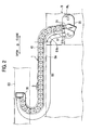
- Fig. 2 is a schematic plan view of the cable-installing and supporting portion structure in an open condition of the slide door SD.
- Fig. 3 is a view showing the process of opening and closing the slide door SD.
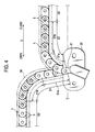
- Fig. 4 is an enlarged view of an important portion of the cable-installing and supporting portion structure disposed at a vehicle body.
- This cable-installing and supporting portion structure serves to guide and bend a cable 2 (shown only in Fig. 6 ) installed between the vehicle body B and the slide door SD, and this structure comprises a cable guide 1, the cable 2, a first support member 20 supporting one end portion of the cable guide 1, and a second support member 30 supporting the other end portion of the cable guide 1.
- the cable 2 includes a wire for supplying electric power to the slide door SD, and at least one wire for feeding a signal between the slide door SD and the vehicle body B, and this cable 2 is installed between the vehicle body B and the slide door SD.
- the cable guide 1 comprises a plurality of link members (links) 3 interconnected into a linear configuration, and the one end portion of this cable guide is supported on the vehicle body B by the first support member 20, while the other end portion thereof is supported on the slide door SD by the second support member 30 (described later).
- the cable 2 is passed through each of the link members 3, and this cable guide 1 guides and bends the cable 2.
- a position P1 indicates a completely-closed (fully closed) condition of the slide door SD
- a position P2 indicates a partially-open (half open) condition of the slide door SD
- a position P3 indicates a completely-open (fully open) condition of the slide door SD.
- the first support member 20 is molded of a resin or the like, and is fixedly secured to the vehicle body by screws (not shown) or the like. More specifically, the first support member is fixedly secured to a lower portion of a door frame of the vehicle body.
- the first support member 20 includes a guide tube 21 for guiding the cable 2 extending from the vehicle body B, and the one end portion of the cable guide 1 is supported by the guide tube 21.
- the cable 2 extends from the vehicle body B, and passes through the guide tube 21 to extend outwardly from the vehicle body B, and is passed through the cable guide 1 in a guided manner.
- the guide tube 21 and the link member 3, disposed at the one end portion of the cable guide 1, are interconnected by a similar structure (described later in detail) to a structure for interconnecting the adjacent link members 3.
- the guide tube 21 is directed toward the slide door SD; and supports the one end portion of the cable guide 1 and one end portion of the cable 2 in such a manner that these one end portions are directed toward the slide door SD in non-parallel relation to a direction Q of sliding movement of the slide door SD.
- the guide tube 21 is slightly inclined toward a rear side of the vehicle body B (that is, in a direction away from the second support member 30 in the fully closed condition), and therefore the one end portion of the cable guide 1 and the one end portion of the cable 2 are supported in a manner to be directed slightly obliquely rearwardly relative to the vehicle body B.
- the second support member 30 is molded of a resin or the like, and is fixedly secured to the slide door SD by screws (not shown) or the like. More specifically, the second support member is fixedly secured to a lower portion of the slide door SD.
- the second support member 30 and the other end portion of the cable guide 1 are interconnected by a similar structure (described later in detail) to the structure for interconnecting the adjacent link members 3.
- the second support member 30 In the fully closed condition of the slide door SD, the second support member 30 is located forwardly of the first support member 20, that is, disposed closer to the front side of the vehicle than the first support member 20 is. In this condition, the second support member 30 supports the other end portion of the cable guide 1 and the other end portion of the cable 2 in such amanner that these other end portions are directed toward the first support member 20 along the sliding direction Q. In this condition, when the slide door SD is opened, the second support member 30 is moved rearward to pass by the first support member 20. Therefore, in the fully open condition of the slide door SD, the second support member 30 supports the other end portion of the cable guide 1 and the other end portion of the cable 2 in such a manner that these other end portions are directed away from the first support member 20 along the sliding direction Q.
- the slide door SD when the slide door SD is fully opened, the slide door SD is shifted outwardly from the vehicle body because of the opening/closing structure of the slide door SD. Therefore, the distance between the first support member 20 and the second support member 30 in a direction perpendicular to the direction Q of sliding movement of the slide door SD is larger in the fully open condition than in the fully closed condition.
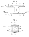
- the link member 3 includes a body portion 11, a pair of projections 13 which are formed. on one end portion of the body portion 11, and function respectively as rotation shafts, apair of reception portions (receiving holes in this embodiment) 15 which are provided at the other end portion of the body portion 11, and are adapted to rotatably support the respective projections 13 of the mating link member 3 to be connected to this link member 3, a pair of first abutment portions 17 formed at the one end portion of the body portion 11, and a pair of second abutment portions 19 formed at the other end portion of the body portion 11.
- the link member 3 is made of a resin or the like.
- the body portion 11 has a generally rectangular tubular shape, and has such an inner size as to pass the cable 2 therethrough.
- the projections 13 are formed on and project respectively from extension portions 11a extending respectively from opposed portions (upper and lower side wall portions in Fig. 5 ) at an open portion in the one end portion of the body portion 11.
- the reception portions 15 are provided respectively at extension portions 11b extending respectively from opposed portions (upper and lower side wall portions in Fig. 5 ) at an open portion in the other end portion of the body portion 11.
- the projections 13 and the reception portions 15 are formed such that an axis, interconnecting the two projections 13, is parallel to an axis interconnecting the two reception portions 15 (that is, these axes extend in the same direction).
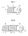
- the distance between the two extension portions 11b, each having the reception portion 15, is slightly larger than the distance between the two extension portions 11a each having the projection 13. Therefore, as shown in Fig. 8 , at an interconnecting portion between the link members 3, the two link members 3A and 3B are interconnected in such a manner that the two projections 13 of one link member 3A (see Fig. 8 ) are fitted respectively into the reception portions 15 of the other link member 3B (see Fig. 8 ) from the inner side. In this interconnected condition, the projections 13 are rotatably held in the reception portions 15, respectively, and therefore the bending angle can be varied at the interconnecting portion between the two link members 3A and 3B.
- the first and second abutment portions 17 and 19 serve as means for limiting a bending direction R (see Fig. 8 ) at the interconnecting portion between the link members 3, and are so arranged that when the two link members 3A and 3B are interconnected, the first abutment portions 17 abut against the second abutment portions 19, respectively, with the two interconnected link members 3A and 3B extending linearly. Because of the provision of the abutment portions 17 and 19, the bending direction R is so limited that at the interconnecting portion, one link member 3A is allowed to be bent relative to the other link member 3B only in one bending direction R from the linearly-extending condition.
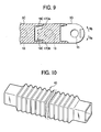
- interconnected link members can be bent within a predetermined bending angle in both directions from a linear condition, and in this case, for example, when link members 3C and 3D are interconnected as shown in Fig. 9 , abutment portions 17Da and 17Db are spaced a predetermined distance from abutment portions 19C, respectively, in a linear condition, and when the link member 3D is bent relative to the link member 3C in either bending direction Ra, Rb at the predetermined angle, the abutment portion 17Da, 17Db is brought into abutting engagement with the corresponding abutment portion 19C.
- the cable guide 1 includes a first section S1 disposed at the vehicle body B, and a second section S2 disposed at the slide door SD.
- the first section S1 can be bent in both directions from the generally-linear condition, and the angle of bending of each interconnecting portion between the link members 3 of this first section S1 is so determined that the cable guide 1 will not interfere with any members provided at the vehicle body B.
- the first section S1 includes a section S1a having the plurality of link members 3 so interconnected as to be bent only in one direction from the linear condition, and a section S1b having the plurality of link members 3 so interconnected as to be bent in both directions from the linear condition. Namely, all of the interconnecting portions of the first section S1 are not bendable in both directions, but this first section S1 is bendable in both directions as a whole with respect to the longitudinal direction.
- the section S1a which is bendable only in the one direction is that portion of the first section S1 disposed at the vehicle body B, and here the section, including one interconnecting portion between the link member 3 and the first support member 20 and two interconnecting portions each between the corresponding link members 3, is the section S1a bendable only in the one direction (see Fig. 4 ).
- the section S1b which is bendable in both directions is that portion of the first section S1 disposed adjacent to the second section S2 (that is, disposed at the slide door SD), and here the section, including four interconnecting portions each between the corresponding link members 3, is the section S1b bendable in both directions (see Fig. 4 ).
- the angle of bending of the section S1a (which is bendable only in the one direction) of the first section S1 toward the rear side of the vehicle is 0 degree
- the section S1b (which is bendable in both directions) can be bent at an angle of 20 degrees toward the rear side of the vehicle at each of the four interconnecting portions each between the link members 3.
- the cable guide 1 extends away from the vehicle body B, and is bent at the first section S1 to extend toward the second support member 30.
- the cable guide 1 extends away from the vehicle body B at the section S1a, and is bent toward the rear side of the vehicle body B at the section S1b.
- the bending angle and bending direction of the interconnecting portions each between the link members 3 at the first section S1 are suitably changed, depending on the mounting positions, shapes, etc., of the various members (the body itself, the rail RL and so on) of the vehicle body B.
- the second section S2 can be bent only in one direction from the generally linear condition.
- the second section S2 extends linearly toward the second support member 30.
- the second section S2 is bent clockwise (in Figs. 3 and 4 ), and is inverted into a generally recumbent J-shape to.extend toward the second support member 30.
- the cable guide 1 is covered with a tube member 40 shown in Fig. 10 .
- the tube member 40 is made of an elastic material such' as rubber and an elastic plastics material, and is formed into a tubular shape, and can be flexed.
- this tube member is in the form of a bellows so that it can be easily flexed, it does not always need to be formed into a bellows.
- the cable guide when the slide door SD is in the fully closed condition, the cable guide is in a condition (first bending condition) in which the whole of the first section S1 is bent clockwise while the second section S2 extends in the generally linear condition.
- the section 51a (bendable only in the one direction) of the first section S1 extends linearly, while the section S1b, bendable in both directions, is bent in the opposite direction.
- the second section S2 which can be bent only in the one direction is gradually bent in such a manner that this bending proceeds from the link member 3, disposed adjacent to the first section S1, toward the link members 3 disposed at the slide door SD. Therefore, when opening the slide door SD, the bending mode of the cable guide 1 is limited to the predetermined mode.
- the second section S2 In the fully open condition of the slide door SD, the second section S2 is inverted into a generally J-shape, and extends toward the second support member 30 (second bending condition).
- the cable guide When closing the slide door SD, the cable guide is bent and deformed in a manner reverse to the above-mentioned manner.
- the cable guide 1 extends away from the vehicle body B, and further extends toward the second support member 30. Therefore, the cable guide can be prevented from interference with other members of the vehicle body B (that is, the body portion Ba of the vehicle body B provided at the rear side of the slide door frame, and the rail RL for the slide door SD in this embodiment).
- the first section S1 includes the section S1a having the plurality of link members 3 so interconnected as to be bent only in the one direction from the linear condition, and the section S1b having the plurality of link members 3 so interconnected as to be bent in both directions from the linear condition. Therefore, the manner of extending of the cable guide 1 away from the vehicle body B can be easily changed between the first bending condition and the second bending condition.
- the second section S2 of the cable guide 1 can be bent only in the one direction, and therefore this second section S2 can also be prevented from interference with the other members.
- the one end portion of the cable guide 1 is supported by the first support member 20 in such a manner that this one end portion is inclined toward the rear side of the vehicle, and therefore when opening the slide door SD, a force, acting on the second section S2 of the cable guide 1 in the direction of the length thereof, can be easily converted into a force to smoothly bend the first section S1 and so on in the opposite direction. This prevents the buckling, etc., of the second section S2, so that the cable guide 1 can be easily smoothly bent and deformed from the first bending condition into the second bending condition.
- the cable guide 1 is covered with the flexible tube member 40 of a tubular shape, and therefore waterproof, dust-proof measures and so on for the cable 2 can be provided. And besides, the production of a sound, resulting from a relative movement between the adjacent link members, can be prevented.
- the cable guide extends away from the vehicle body, and further extends toward the second support member, and therefore the cable guide can be prevented from interference with the other members of the vehicle body.
- the direction of bending of the second section of the cable guide is limited to the predetermined direction, and therefore the second section can be prevented from interference with other members.
- the cable guide when sliding the slide door, is smoothly bent and deformed from the first bending condition into the second bending condition.
- the angle of bending of the first section of the cable guide is so determined that the cable guide will not interfere with any member of the vehicle body, and therefore the interference with the vehicle body can be more positively prevented.
- the first section of the cable guide includes the section which can be bent only in the one direction from the generally linear condition, and therefore the manner of extending of the cable guide away from the vehicle body can be easily changed between the first bending condition and the second bending condition.
- waterproof and dust-proof measures and so on for the cable can be provided.
- Fig. 11 is a plan view of a power supply apparatus for a vehicle slide door in a vehicle (automobile) , employing a second preferred embodiment of the present invention.
- Fig. 12 is a view showing the manner of opening and closing the slide door in the power supply apparatus of Fig. 11 .
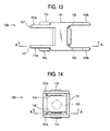
- This power supply apparatus comprises the cable guide 101 shown in Figs. 11 and 12 , and a power supply cable 102 (see Fig. 14 ) .
- the cable guide 101 comprises a plurality of link members 103 interconnected into a linear configuration, and one end portion of this cable guide 101 is connected to a vehicle body-side mounting portion (fixing-side mounting portion) 105a of a vehicle body (fixing structure) 105, while the other end portion thereof is connected to a door-side mounting portion (moving-side mounting portion) 107a of the slide door (moving structure) 107.
- the power supply cable 102 is guided by the cable guide 101, and is installed between the vehicle body 105 and the slide door 107.
- each of the link member 103 forming the cable guide 101, includes a body portion 111, a pair of projections 113 which are formed on one end portion of the body portion 111, and which function respectively as rotation shafts, a pair of reception portions (receiving holes in this embodiment) 115 which are provided at the other end portion of the body portion 111, and are adapted to rotatably support the respective projections 113 of the mating link member 103 to be connected to this link member 103, a pair of first abutment portions 117 formed at the one end portion of the body portion 111, and a pair of second abutment portions 119 formed at the other end portion of the body portion 111.
- the link member 103 is made of a resin.
- the body portion 111 has a generally rectangular tubular shape, and has such an inner size as to pass the power supply cable 102 therethrough.
- the projections 113 are formed on and project respectively from extension portions 111a extending respectively from opposed portions (upper and lower side wall portions in Fig. 13 ) at an open portion in the one end portion of the body portion 111.
- the reception portions 115 are provided respectively at extension portions 111b extending respectively from opposed portions (upper and lower side wall portions in Fig. 13 ) at an open portion in the other end portion of the body portion 111.
- the projections 113 and the reception portions 115 are formed such that an axis, interconnecting the two projections 113, is parallel to an axis interconnecting the two reception portions 115 (that is, these axes extend in the same direction).
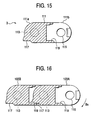
- the distance between the two extension portions 111b, each having the reception portion 115, is slightly larger than the distance between the two extension portions 111a each having the projection 113. Therefore, as shown in Fig. 16 , at an interconnecting portion between the link members 103, the two link members 103A and 103B are interconnected in such a manner that the two projections 113 of one link member 103A (see Fig. 16 ) are fitted respectively into the reception portions 115 of the other link member 103B (see Fig 16 ) from the inner side. In this interconnected condition, the projections 113 are rotatably held in the reception portions 115, respectively, and therefore the bending angle can be varied at the interconnecting portion between the two link members 103A and 103B.
- the first and second abutment portions 117 and 119 serve as means for limiting a bending direction B (see Fig. 16 ) at the interconnecting portion between the link members 103, and are so arranged that when the two link members 103A and 103B are interconnected, the first abutment portions 117 abut against the second abutment portions 119, respectively, with the two interconnected link members 103A and 103B extending linearly. Because of the provision of the abutment portions 117 and 119, the bending direction B1 is so limited that at the interconnecting portion, one link member 103A is allowed to be bent relative to the other link member 103B only in one bending direction B from the linearly-extending condition.
- the cable guide 101 includes a first section C1 and a second section C2 which extend in a longitudinal direction.
- the link members 103 are interconnected such that the bending directions B1 of the interconnecting portions in the same section C1, C2 are set to the same direction and that the bending direction of each interconnecting portion in the section C1 is opposite to the bending direction of each interconnecting portion in the section C2.
- the lengths of the sections C1 and C2 are not particularly specified, the length of the section C1 is smaller than the length of the section C2 in Fig. 11 . Namely, when viewed from the vehicle body-side mounting portion (105a) side, the bending direction B1 of each interconnecting portion in the first section C1 is a counterclockwise direction (in Fig. 11 ) , while the bending direction of each interconnecting portion in the second section C2 is a clockwise direction (in Fig. 11 ).
- the cable guide 101 of this construction is installed between the vehicle body-side mounting portion 105a and the door-side mounting portion 107a so that during the movement of the slide door 107, this cable guide 101 can be bent into a generally S-shape (when viewed from the top) in such a manner that the distance between the vehicle body-side mounting portion 105a and the door-side mounting portion 107a becomes a minimum.
- the link members 103 disposed respectively at the opposite ends of the cable guide 101, are rotatably connected at interconnecting portions 121 and 123 to the vehicle body-side mounting portion 105a and the door-side mounting portion 107a, respectively.
- the door-side mounting portion 107 a moves in a sliding direction, spaced a predetermined distance from the vehicle body-side mounting portion 105a, between two positions disposed respectively on opposite sides of the vehicle body-side mounting portion 105a serving as an intermediate position.
- the distance between the vehicle body-side mounting portion 105a and the door-side mounting portion 107a is the largest, and also the cable guide 101 extends generally linearly in the direction of sliding of the slide door 107. More specifically, the section C2 is disposed in a generally linear condition, and the section C1 is bent in a stepped manner to absorb the distance between the vehicle body-side-mounting portion 105a and the door-side mounting portion 107a. In this condition, the door-side mounting portion 107a and the vehicle body-side mounting portion 105a support the opposite end portions of the cable guide 101, respectively, in such a manner that these opposite end portions are generally opposed to each other along the sliding direction.
- the vehicle body-side mounting portion 105a and the door-side mounting portion 107a approach each other, and the distance between the two is smaller in this condition than in the fully closed condition, so that a slack portion develops in the cable guide 101.
- the distance between the vehicle body-side mounting portion 105a and the door-side mounting portion 107a is the smallest, and the amount of slackening of the cable guide 101 is the largest.
- That portion of the section C2, disposed close to the section C1 is bent into a generally U-shape, while that portion of the section C2, disposed close to the fixed end thereof, is disposed in a linear condition, and also the section C1 is bent into a generally arcuate shape in the opposite direction.
- the generally arcuately-bent portion of the section C1 and the generally U-shaped bent portion of the section C2 jointly form a generally S-shaped bent portion when viewed from the top.
- the door-side mounting. portion 107a which has passedby the vehicle body-side mounting portion 105a, is disposed at a rear portion of the vehicle. In this condition, the distance between the vehicle body-side mounting portion 105a and the door-side mounting portion 107a is smaller than in the fully-closed condition, so that a slack portion develops in the cable guide 101.
- the cable guide 101 is forcibly bent into the generally S-shape when viewed from the top, thereby absorbing the slack of the cable guide 101.
- the cable guide 101 is formed by interconnecting the link members 103 of a generally tubular shape, and therefore has a hollow shape.
- the power supply cable 102 is passed through the cable guide 101, and is installed to extend from the vehicle body to the slide door.
- the cable guide 101 can be bent into the generally S-shape when viewed from the top. Therefore, when the cable guide is slackened during the opening and closing operations of the slide door 107 (in the half open condition or the fully open condition of the slide door 107 in this embodiment), the slackened shape of the cable guide 101 is forcibly formed into the generally S-shape when viewed from the top, thereby absorbing the slack of the cable guide 1 while stabilizing the slackened shape thereof.
- the length of the cable guide 101, as well as the length of the power supply cable 102 can be properly determined in accordance with the amount of movement of the slide door 107 and so on, and therefore the power supply cable 102 can be shortened, and as a result an electrical transmission loss and the cost of the wire can be reduced.
- this construction can easily meet a size change of the power supply cable 102.
- the power supply cable 102 is prevented from being twisted in accordance with the movement of the slide door 107.
- the power supply cable 102 is passed through the cable guide 101, and is installed, and therefore the cable 102 can be positively and easily installed along the cable guide 101, and besides the cable 102 can be protected by the cable guide 101.
- the cable guide 101 can be formed, using the link members 103 of the simple structure.
- the cable guide of this embodiment is applied to the apparatus for supplying electric power to the slide door
- the cable guide of this embodiment can be used for installing a cable which need to be installed between an arbitrary fixing structural member and an arbitrary moving structural member.
- the cable guide can be used for installing a cable between a seat, slidably mounted on the vehicle body, and the vehicle body, and for installing a cable between the vehicle body and a sun roof-opening/closing member.
- the power supply cable is guided by the cable guide., and is installed between the vehicle body and the slide door, and therefore electric power can always be supplied to the slide door regardless of whether the slide door is open or closed.
- the intermediate portion of the cable guide 1 in the longitudinal direction can be bent into the generally S-shape when viewed from the top. Therefore, when the cable guide is slackened during the opening and closing operations of the slide door, the slackened shape of the cable guide is forcibly formed into the generally S-shape when viewed from the top, thereby absorbing the slack of the cable guide while stabilizing the slackened shape thereof. Therefore, it is not necessary to provide any means for receiving the cable guide and the cable, installed by this cable guide, when the cable guide is slackened, and also to provided any means for limiting the movement of the cable guide. Therefore, the construction can be simplified.
- the length of the cable guide, as well as the length of the power supply cable can be properly determined in accordance with the amount of movement of the slide door and so on, and therefore the power supply cable can be shortened, and as a result an electrical transmission loss and the cost of the wire can be reduced.
- this construction can easily meet a size change of the power supply cable.
- the power supply cable is prevented from being twisted in accordance with the movement of the slide door.
- the power supply cable is passed through the cable guide, and is installed, and therefore the cable can be positively and easily installed along the cable guide, and besides the cable can be protected by the cable guide.
- the cable guide can be formed, using the link members of the simple structure.
Landscapes
- Engineering & Computer Science (AREA)
- Mechanical Engineering (AREA)
- General Engineering & Computer Science (AREA)
- Electric Cable Arrangement Between Relatively Moving Parts (AREA)
Claims (12)
- Kabelführung (1; 101) zum Führen eines Kabels (2; 102), das zwischen einer fixen bzw. fixierenden bzw. Fixierstruktur (B; 105) und einer sich bewegenden Struktur (SD; 107) installiert ist, umfassend:eine Mehrzahl von Ketten- bzw. Verbindungsgliedern (3; 103), die angepasst sind, zu einer linearen Konfiguration miteinander verbunden zu werden;wobei die Kabelführung (1; 101) eine erste Sektion (S1; C1) und eine zweite Sektion (S2; C2) enthält,
dadurch gekennzeichnet, dassdie Verbindungsglieder (3; 103) der zweiten Sektion (S2; C2) derart konfiguriert sind, dass die zweite Sektion (S2; C2) in der Lage ist, in nur einer Richtung (R; B) aus einem im Allgemeinen linearen Zustand gebogen zu werden, unddie Verbindungsglieder (3; 103) der ersten Sektion (S1; C1) derart konfiguriert sind, dass die erste Sektion (S1; C1) in der Lage ist, in zumindest einer Richtung (R; B) entgegengesetzt zu der einen Richtung der zweiten Sektion (S2; C2) aus einem im Allgemeinen linearen Zustand gebogen zu werden. - Kabelführung (1; 101) nach Anspruch 1,
wobeidie Mehrzahl von Verbindungsgliedern (3; 103) durch verbindende Abschnitte miteinander verbunden sind;eine Biegerichtung jedes der verbindenden Abschnitte so begrenzt ist, dass eines von zwei beliebigen, angrenzenden bzw. benachbarten miteinander verbundenen Verbindungsgliedern sich relativ zu dem anderen Verbindungsglied in nur einer Richtung aus einem sich linear erstreckenden Zustand biegen kann bzw. darf;die erste Sektion (S1; C1) eine erste Teil- bzw. Untersektion (S1a) umfasst, wo die Biegerichtungen der verbindenden Abschnitte auf die gleiche Richtung festgesetzt sind wie die eine Biegerichtung der zweiten Sektion (S2; C2);die erste Sektion (S1; C1) eine zweite Teil- bzw. Untersektion (S1 b) umfasst, wo die Biegerichtung jedes verbindenden Abschnitts entgegengesetzt zu der einen Biegerichtung jedes verbindenden Abschnitts in der zweiten Sektion (S2; C2) ist;und während der Gleit- bzw. Schiebebewegung der sich bewegenden Struktur kann ein mittlerer bzw. Zwischenabschnitt der Kabelführung (1; 101) in der Längsrichtung von oben betrachtet in eine im Allgemeinen S-Form gebogen werden. - Kabelführung (1; 101) nach Anspruch 2, wobei jedes der Mehrzahl von Verbindungsgliedern (3; 103) eine im Allgemeinen rohrförmige Form aufweist, so dass das Kabel (2) durch das Verbindungsglied (3; 103) geführt werden kann; und
das Kabel (2) durch die Kabelführung (1; 101) geführt wird, um installiert zu werden. - Kabelführung (1; 101) nach Anspruch 3,
wobei jedes der Mehrzahl von Verbindungsgliedern (3; 103) enthält:einen Körperabschnitt (11; 111) einer im Allgemeinen rohrförmigen Form;Vorsprünge (13; 113), die jeweils auf gegenüberliegenden bzw. entgegengesetzten Seitenwänden eines Endabschnitts des Körperabschnitts (11; 111) gebildet sind und die jeweils als Drehwellen fungieren;Aufnahmeabschnitte (15; 115), die jeweils an gegenüberliegenden bzw. entgegengesetzten Seitenwänden des anderen Endabschnitts des Körperabschnitts (11; 111) derart vorgesehen sind, dass die Achsen der Aufnahmeabschnitte (15; 115) parallel zu den Achsen der Vorsprünge der zusammenpassenden bzw. dazugehörenden Verbindungsglieder (3D) sind, die mit dem Verbindungsglied (3C) zu verbinden sind, wobei die Vorsprünge (13; 113) in die Aufnahmeabschnitte (15; 115) gepasst sind, um drehbar gelagert zu sein;einen ersten Anlageabschnitt (17; 117), der an dem einen Endabschnitt des Körperabschnitts (11; 111) gebildet ist; undeinen zweiten Anlageabschnitt (19; 119), der an dem anderen Endabschnitt des Körperabschnitts (11; 111) gebildet ist, um gegen den ersten Anlageabschnitt (17; 117) des zusammenpassenden bzw. dazugehörenden Verbindungsglieds (3D) anzuliegen, wodurch der Drehbereich des zusammenpassenden bzw. dazugehörenden Verbindungsglieds (3D) begrenzt wird. - Leistungsversorgungsvorrichtung für die Schiebetür (SD) eines Fahrzeugs, umfassend:ein Kabel (2), das zwischen einem Körper bzw. Karosserie (B) des Fahrzeugs und der Schiebetür (SD) installiert ist;
gekennzeichnet durcheine Kabelführung (1; 101) nach einem der vorhergehenden Ansprüche. - Leistungsversorgungsvorrichtung für die Schiebetür eines Fahrzeugs nach Anspruch 5, ferner umfassend:ein erstes Stütz- bzw. Trägerglied (20), das an dem Fahrzeugkörper (B) vorgesehen ist und einen Endabschnitt der Kabelführung (1) auf eine solche Weise stützt bzw. trägt, dass der eine Endabschnitt zu der Schiebetür (SD) hin in nicht paralleler Beziehung zu einer Richtung der Gleitbewegung der Schiebetür (SD) gerichtet ist; undein zweites Stütz- bzw. Trägerglied (30), das an der Schiebetür (SD) vorgesehen ist und den anderen Endabschnitt der Kabelführung (1) stützt bzw. trägt, wobei das zweite Stütz- bzw. Trägerglied (30) in der Lage ist, sich zu bewegen, um das erste Stütz- bzw. Trägerglied (20) gemäß der Gleitbewegung der Schiebetür (SD) zu passieren;wobei die erste Sektion (S1) an dem Fahrzeugkörper (B) angeordnet ist und die zweite Sektion (S2) an der Schiebetür (SD) angeordnet ist;die erste Sektion (S1) in der einen Richtung (R; B) der zweiten Sektion (S2) und in der entgegengesetzten Richtung dazu aus dem im Allgemeinen linearen Zustand gebogen werden kann; undsich die Kabelführung (1), gemäß der Gleitbewegung der Schiebetür (SD), von dem Fahrzeugkörper (B) aus weg erstreckt und an der ersten Sektion (S1) gebogen ist, um sich zu dem zweiten Stütz- bzw. Trägerglied (30) hin zu erstrecken.
- Leistungsversorgungsvorrichtung für die Schiebetür eines Fahrzeugs nach Anspruch 6,
wobeidie Kabelführung (1) zwischen einem ersten Biegezustand und einem zweiten Biegezustand gemäß der Gleitbewegung der Schiebetür (SD) gebogen und verformt werden kann;sich die Kabelführung (1) in dem ersten Biegezustand von dem Fahrzeugkörper (B) aus weg erstreckt und sich weiter im Allgemeinen linear zu dem zweiten Stütz- bzw. Trägerglied (30) hin erstreckt; undsich die Kabelführung (1) in dem zweiten Biegezustand von dem Fahrzeugkörper (B) aus weg erstreckt und weiter zu einer im Allgemeinen J-Form umgekehrt bzw. invertiert ist, um sich zu dem zweiten Stütz- bzw. Trägerglied (30) hin zu erstrecken. - Leistungsversorgungsvorrichtung für die Schiebetür eines Fahrzeugs nach Anspruch 7,
wobei das erste Stütz- bzw. Trägerglied (20) in dem ersten Biegezustand den einen Endabschnitt der Kabelführung (1) auf eine solche Weise stützt bzw. trägt, dass der eine Endabschnitt von dem zweiten Stütz- bzw. Trägerglied (30) weg relativ zu einer Richtung senkrecht zu der Richtung der Gleitbewegung der Schiebetür (SD) geneigt ist. - Leistungsversorgungsvorrichtung für die Schiebetür eines Fahrzeugs nach Anspruch 6, 7 oder 8,
wobei eine Biegewinkel jedes verbindenden Abschnitts zwischen den Verbindungsgliedern (3) der ersten Sektion (S1) derart bestimmt bzw. festgelegt ist, dass die Kabelführung (1) keines der Glieder beeinträchtigt, die an dem Fahrzeugkörper (B) vorgesehen sind. - Leistungsversorgungsvorrichtung für die Schiebetür eines Fahrzeugs nach Anspruch 6, 7, 8 oder 9,
wobei die Kabelführung (1) mit einem flexiblen Rohrglied von rohrförmiger Form abgedeckt bzw. bedeckt ist. - Fahrzeug, umfassend:einen Fahrzeugkörper bzw. -karosserie (B; 105);eine sich bewegende Struktur (SD; 107); die gleitbar bzw. verschiebbar an dem Fahrzeugkörper (B; 105) montiert ist;ein Kabel (2; 102), das zwischen dem Fahrzeugkörper (B; 105) und der sich bewegenden Struktur (SD; 107) installiert ist;
gekennzeichnet durcheine Kabelführung (1; 101) nach einem der Ansprüche 1 bis 4 zum Führen des Kabels (2; 102). - Fahrzeug nach Anspruch 11, wobei die sich bewegende Struktur eine Schiebetür (SD) des Fahrzeugs ist.
Applications Claiming Priority (6)
| Application Number | Priority Date | Filing Date | Title |
|---|---|---|---|
| JP2002184501A JP3850758B2 (ja) | 2002-06-25 | 2002-06-25 | スライドドアのケーブル配索支持部構造 |
| JP2002184501 | 2002-06-25 | ||
| JP2002191684A JP2004034759A (ja) | 2002-07-01 | 2002-07-01 | 車両用スライドドアの給電装置 |
| JP2002191684 | 2002-07-01 | ||
| JP2002191683 | 2002-07-01 | ||
| JP2002191683A JP2004040863A (ja) | 2002-07-01 | 2002-07-01 | ケーブルガイド |
Publications (2)
| Publication Number | Publication Date |
|---|---|
| EP1375259A1 EP1375259A1 (de) | 2004-01-02 |
| EP1375259B1 true EP1375259B1 (de) | 2010-01-06 |
Family
ID=29718637
Family Applications (1)
| Application Number | Title | Priority Date | Filing Date |
|---|---|---|---|
| EP03013477A Expired - Lifetime EP1375259B1 (de) | 2002-06-25 | 2003-06-25 | Kabelführung und Energieversorgungsapparat für eine Kraftfahrzeugschiebetür |
Country Status (3)
| Country | Link |
|---|---|
| US (1) | US7082720B2 (de) |
| EP (1) | EP1375259B1 (de) |
| DE (1) | DE60330829D1 (de) |
Families Citing this family (36)
| Publication number | Priority date | Publication date | Assignee | Title |
|---|---|---|---|---|
| WO2004106680A1 (de) * | 2003-06-02 | 2004-12-09 | Knorr-Bremse Ges.M.B.H. | Überleitung von leitungen zu einem türblatt |
| DE10343029A1 (de) * | 2003-09-16 | 2005-04-07 | Kabelschlepp Gmbh | Schiebetürsystem für ein Fahrzeug, insbesondere für ein Kraftfahrzeug mit einer Energieführungskette |
| US7730669B2 (en) | 2003-09-22 | 2010-06-08 | Sumitomo Wiring Systems, Ltd. | Device for guiding a conductor path for slide door |
| US20060059782A1 (en) * | 2004-09-20 | 2006-03-23 | Hi-Lex Corporation | Cord support for window regulator |
| DE102004058870B4 (de) * | 2004-12-06 | 2012-11-22 | Brose Fahrzeugteile Gmbh & Co. Kommanditgesellschaft, Coburg | Schiebetür für Kraftfahrzeuge und Verfahren zu deren Montage |
| JP4467063B2 (ja) * | 2005-01-27 | 2010-05-26 | 本田技研工業株式会社 | スライドシート給電装置 |
| JP2006327328A (ja) * | 2005-05-24 | 2006-12-07 | Honda Motor Co Ltd | ハーネスの配索構造 |
| JP4721043B2 (ja) * | 2005-06-14 | 2011-07-13 | 住友電装株式会社 | スライドドアのハーネスガイド |
| JP4997944B2 (ja) * | 2006-03-07 | 2012-08-15 | 日産自動車株式会社 | 給電ユニット |
| WO2007132419A2 (en) * | 2006-05-17 | 2007-11-22 | Koninklijke Philips Electronics N.V. | Medical diagnostic apparatus and hose suitable for guiding connections in a medical diagnostic apparatus |
| WO2008015935A1 (fr) * | 2006-07-31 | 2008-02-07 | The Furukawa Electric Co., Ltd. | Dispositif de fourniture d'électricité pour porte coulissante |
| JP4783307B2 (ja) * | 2006-11-13 | 2011-09-28 | 矢崎総業株式会社 | スライド構造体用の給電装置 |
| JP5012063B2 (ja) * | 2007-02-05 | 2012-08-29 | 住友電装株式会社 | 自動車用ワイヤハーネスの配索構造 |
| NL1033511C2 (nl) * | 2007-03-07 | 2008-09-09 | Lake Nassau B V | Liftsysteem voor een paneel en werkwijze voor het vrijgeven en intrekken van een paneel. |
| JP4913690B2 (ja) * | 2007-07-27 | 2012-04-11 | 古河電気工業株式会社 | スライドドア用給電装置 |
| EP2320533B1 (de) * | 2008-08-29 | 2013-12-04 | Yazaki Corporation | Kabelbaumführungsstruktur |
| US7984605B2 (en) * | 2008-09-10 | 2011-07-26 | Netapp, Inc. | Cable chain return system and associated methods |
| JP2011200086A (ja) * | 2010-03-24 | 2011-10-06 | Sumitomo Wiring Syst Ltd | 給電用配索構造 |
| EP2397374B1 (de) * | 2010-06-17 | 2012-12-05 | Nexans | Vorrichtung zum Verbinden von Funktionselementen mit einer Versorgungsquelle |
| DE102010038353B4 (de) | 2010-07-23 | 2015-03-05 | S-Y Systems Technologies Europe Gmbh | Vorrichtung zum Anschließen einer Führungskette |
| JP2013049402A (ja) * | 2011-08-02 | 2013-03-14 | Sumitomo Wiring Syst Ltd | ワイヤハーネス配索構造 |
| JP5640940B2 (ja) * | 2011-09-26 | 2014-12-17 | 住友電装株式会社 | スライドドア用ワイヤハーネスの配索構造 |
| JP5846499B2 (ja) * | 2012-09-24 | 2016-01-20 | 住友電装株式会社 | 電線ガイド |
| DE102013100660A1 (de) | 2013-01-23 | 2014-07-24 | Tsubaki Kabelschlepp GmbH | Leitungsführungssystem für ein Fahrzeug |
| US9585474B2 (en) | 2013-07-17 | 2017-03-07 | Whirlpool Corporation | Traveling harness system |
| CN104536539A (zh) * | 2014-12-04 | 2015-04-22 | 英业达科技有限公司 | 电子装置 |
| JP6177816B2 (ja) * | 2015-01-23 | 2017-08-09 | 矢崎総業株式会社 | 湾曲規制部材及び給電装置 |
| US9956928B2 (en) | 2015-06-30 | 2018-05-01 | Fca Us Llc | Track assembly for sliding vehicle door |
| JP6217710B2 (ja) * | 2015-08-19 | 2017-10-25 | 住友電装株式会社 | 電線ガイド装置及びスライドドア用電線ガイドモジュール |
| FR3048203B1 (fr) * | 2016-02-29 | 2019-06-07 | Peugeot Citroen Automobiles Sa | Agencement d'un ensemble de gaines de protection sur un vehicule automobile |
| JP6430991B2 (ja) * | 2016-04-15 | 2018-11-28 | 矢崎総業株式会社 | 湾曲規制部材及び給電装置 |
| CN105735126B (zh) * | 2016-04-25 | 2017-08-08 | 李宾 | 双向伸缩式水平转动电缆伸缩装置 |
| JP6640255B2 (ja) * | 2018-02-20 | 2020-02-05 | 矢崎総業株式会社 | 湾曲規制部材及び給電装置 |
| JP7230605B2 (ja) * | 2019-03-18 | 2023-03-01 | 富士フイルムビジネスイノベーション株式会社 | ハーネス接続構造及び電子機器 |
| AT524181B1 (de) * | 2020-09-08 | 2024-04-15 | Blum Gmbh Julius | Vorrichtung zur Führung eines Stromkabels |
| US12158035B2 (en) | 2022-01-27 | 2024-12-03 | Honda Motor Co., Ltd. | Pinch sensor coupler assembly, vehicle door having same and manufacturing method thereof |
Family Cites Families (44)
| Publication number | Priority date | Publication date | Assignee | Title |
|---|---|---|---|---|
| US3020362A (en) | 1956-09-06 | 1962-02-06 | Kabelschlepp Gmbh | Means for delivering power supply to travelling machine elements |
| US3053358A (en) | 1961-07-05 | 1962-09-11 | Porter Co Inc H K | Adjustable cable way connector |
| US3284036A (en) | 1965-05-06 | 1966-11-08 | Nat Crane Corp | Carrier link chain assembly for hoses |
| US3330105A (en) | 1965-06-23 | 1967-07-11 | Maysteel Products Corp | Protective device for flexible conductors |
| US3347038A (en) | 1965-06-24 | 1967-10-17 | Teppert Anton | Band-shaped jewelry |
| US3716986A (en) | 1970-10-21 | 1973-02-20 | Gemco Electric Co | Rolling conductor support |
| DE2237600B2 (de) | 1972-07-31 | 1975-05-07 | Amsted-Siemag Kette Gmbh, 5240 Betzdorf | Gliederförderband aus mehreren gelenkig miteinander verbundenen metallischen Plattengliedern |
| US3779003A (en) | 1972-09-07 | 1973-12-18 | Measurex Corp | Cable carrier with removable plastic links |
| DE2360227C3 (de) | 1973-12-04 | 1981-08-20 | Kabelschlepp Gmbh, 5900 Siegen | Energieführungskette |
| DE2362463B2 (de) | 1973-12-15 | 1978-03-16 | Kabelschlepp Gmbh, 5900 Siegen | Anordnung für die Führung von Energieleitungen |
| US4253027A (en) | 1978-06-14 | 1981-02-24 | Ohio-Nuclear, Inc. | Tomographic scanner |
| DE3040076C1 (de) | 1980-10-24 | 1982-06-03 | Kabelschlepp Gmbh, 5900 Siegen | Energieleitungstraeger |
| US4392344A (en) | 1981-06-30 | 1983-07-12 | Central Safety Equipment Company | Chain-link cable carrier |
| DE3241924C2 (de) | 1982-11-12 | 1986-09-25 | Schubert & Salzer Maschinenfabrik Ag, 8070 Ingolstadt | Vorrichtung zum Führen von flexiblen Versorgungsleitungen |
| US4462565A (en) | 1983-01-17 | 1984-07-31 | Lockheed Corporation | Erectable and retractable support for rolling conductor track |
| US4582281A (en) | 1983-06-06 | 1986-04-15 | Sine Products Company | Flexible support and carrier assembly |
| DE3333543C3 (de) | 1983-09-16 | 1995-02-09 | Ernst Klein | Selbsttragender Energieleitungsträger |
| DE3407169C2 (de) | 1984-02-28 | 1986-01-23 | Kabelschlepp Gmbh, 5900 Siegen | Energieführungskette |
| DE3414412C1 (de) | 1984-04-17 | 1987-11-12 | Kabelschlepp Gmbh, 5900 Siegen | Energiefuehrungskette |
| DE3419477C1 (de) * | 1984-05-24 | 1985-11-28 | Hörmann KG Antriebs- und Steuerungstechnik, 4834 Harsewinkel | Getriebe zur UEberfuehrung einer rotatorischen in eine translatorische Bewegung |
| DE3432273A1 (de) | 1984-09-01 | 1986-03-13 | Malkmus-Dörnemann, geb. Dörnemann, Carola, Dr., 3320 Salzgitter | Seitenschiebetor |
| DE3507200A1 (de) | 1985-03-01 | 1986-09-04 | Kabelschlepp Gmbh, 5900 Siegen | Energiefuehrungskette |
| DE3603121A1 (de) * | 1986-02-01 | 1987-10-29 | Hoermann Kg Antrieb Steuertec | Geraet zur ueberfuehrung einer rotatorischen in eine translatorische bewegung mittels zweier in speichertrommeln ueberfuehrbaren straenge |
| IT208046Z2 (it) | 1986-09-15 | 1988-03-31 | Tecno Mobili E Forniture Per A | Organo passocavo flessibile a snodi bidirezionali. |
| IT209828Z2 (it) | 1987-01-02 | 1988-11-04 | Mauri Giovanni | Catena portacavi a sviluppo curvilineo.! |
| GB8801707D0 (en) | 1988-01-26 | 1988-02-24 | Dunn W H & Son Ltd | Line protecting apparatus |
| IT1239969B (it) | 1990-05-11 | 1993-11-27 | Magitex | Canalina per il supporto di una catena porta condutture e un apparato mobile per la pulizia di un impianto tessile |
| US5083472A (en) | 1991-02-08 | 1992-01-28 | Kang Ho Y | Automatic opening and/or closing apparatus for use in a sliding door to an automobile |
| DE4131762C2 (de) * | 1991-09-24 | 1997-05-22 | Winkhaus Fa August | Betätigungsvorrichtung für einen Flügel eines Fensters, einer Tür, einer Lüftungsklappe oder dergleichen |
| JP2574103B2 (ja) * | 1992-08-04 | 1997-01-22 | 中川機械工業株式会社 | 揺動開閉体の支持構造 |
| US5581944A (en) * | 1993-07-08 | 1996-12-10 | The Stanley Works | Electrical link and sensor system for automatic sliding doors |
| DE4433678C2 (de) | 1994-09-21 | 1996-08-08 | Igus Gmbh | Energieführungskette mit Führungsanschlag |
| AU693607B2 (en) | 1994-10-18 | 1998-07-02 | Smed, Inc | Cable carriers |
| DE19512088C2 (de) | 1995-04-03 | 1997-05-07 | Igus Gmbh | Energiekette |
| DE19605775C1 (de) | 1996-02-16 | 1997-09-25 | Igus Gmbh | Energieführungskette mit Führungsanschlag |
| JP3216872B2 (ja) | 1996-06-12 | 2001-10-09 | 本田技研工業株式会社 | スライドドアと車体とを結ぶハーネス構造 |
| US6174020B1 (en) * | 1998-12-15 | 2001-01-16 | Daimlerchrysler Corporation | Sliding door system for vehicles |
| DE19905022C2 (de) | 1999-01-28 | 2000-11-16 | Apprich Secur 2000 Gmbh | Vorrichtung zum Öffnen und Verschließen einer Öffnung in einer Wandung mittels einer Schiebetür |
| DE29913063U1 (de) * | 1999-07-30 | 2000-02-17 | Igus Spritzgußteile für die Industrie GmbH, 51147 Köln | Energiezuführungskette |
| DE19948852C1 (de) * | 1999-10-08 | 2001-08-16 | Webasto Tuersysteme Gmbh | Innenschwenktür oder Falttür |
| JP3570317B2 (ja) | 1999-12-14 | 2004-09-29 | 住友電装株式会社 | 自動車用スライドドアのワイヤハーネス配索構造 |
| JP3356758B2 (ja) * | 2000-09-13 | 2002-12-16 | 株式会社椿本チエイン | ケーブルドラグチェーン |
| JP3743279B2 (ja) | 2000-10-30 | 2006-02-08 | 日産自動車株式会社 | スライドドアのドアハーネス配索構造 |
| JP2004129479A (ja) * | 2002-08-07 | 2004-04-22 | Yazaki Corp | ハーネス用外装部材とそれを用いたハーネス配索構造 |
-
2003
- 2003-06-24 US US10/602,313 patent/US7082720B2/en not_active Expired - Lifetime
- 2003-06-25 EP EP03013477A patent/EP1375259B1/de not_active Expired - Lifetime
- 2003-06-25 DE DE60330829T patent/DE60330829D1/de not_active Expired - Lifetime
Also Published As
| Publication number | Publication date |
|---|---|
| DE60330829D1 (de) | 2010-02-25 |
| US7082720B2 (en) | 2006-08-01 |
| EP1375259A1 (de) | 2004-01-02 |
| US20040003543A1 (en) | 2004-01-08 |
Similar Documents
| Publication | Publication Date | Title |
|---|---|---|
| EP1375259B1 (de) | Kabelführung und Energieversorgungsapparat für eine Kraftfahrzeugschiebetür | |
| EP1378400B1 (de) | Kabelunterstützungsstruktur | |
| US7482538B2 (en) | Power supply apparatus for sliding structure | |
| CN101743146B (zh) | 滑动门用供电装置 | |
| US7905537B2 (en) | Harness installation structure of link-type movable body | |
| EP1544046B1 (de) | Struktur für installation eines Kabelbaumes einer Tür | |
| US7042738B2 (en) | Power-supply wiring device and harness layout structure by the power-supply wiring device | |
| US20070148992A1 (en) | Harness installation structure | |
| US20040083655A1 (en) | Construction for arranging and supporting a cable of a slide door | |
| US7381898B2 (en) | Electrical connection structure | |
| US7053306B2 (en) | Electricity-feeding device | |
| US20130000941A1 (en) | Power feeding wiring structure | |
| EP0812734B1 (de) | Eine Kraftfahrzeug-Kabelbaum-Bauart | |
| JP3850758B2 (ja) | スライドドアのケーブル配索支持部構造 | |
| JP2008178208A (ja) | スライド構造体用の給電装置 | |
| US7730669B2 (en) | Device for guiding a conductor path for slide door | |
| JP2001151042A (ja) | 自動車用スライドドアへのワイヤハーネス配索構造 | |
| US9112342B2 (en) | Power feeding wiring structure | |
| JPH0920189A (ja) | 可動式ワイヤハーネス | |
| JP2009179118A (ja) | スライドドア給電用ワイヤハーネスの取付構造 | |
| US8276963B2 (en) | Storage structure having a lid | |
| JP2004040863A (ja) | ケーブルガイド | |
| JP5076840B2 (ja) | 開閉体駆動用ラックベルト及び該開閉体駆動用ラックベルトを用いた開閉体駆動装置 | |
| JP2004034759A (ja) | 車両用スライドドアの給電装置 | |
| JP3043589B2 (ja) | 車両用ルーフの開閉装置 |
Legal Events
| Date | Code | Title | Description |
|---|---|---|---|
| PUAI | Public reference made under article 153(3) epc to a published international application that has entered the european phase |
Free format text: ORIGINAL CODE: 0009012 |
|
| AK | Designated contracting states |
Kind code of ref document: A1 Designated state(s): AT BE BG CH CY CZ DE DK EE ES FI FR GB GR HU IE IT LI LU MC NL PT RO SE SI SK TR |
|
| AX | Request for extension of the european patent |
Extension state: AL LT LV MK |
|
| 17P | Request for examination filed |
Effective date: 20040513 |
|
| AKX | Designation fees paid |
Designated state(s): DE FR GB |
|
| GRAP | Despatch of communication of intention to grant a patent |
Free format text: ORIGINAL CODE: EPIDOSNIGR1 |
|
| GRAS | Grant fee paid |
Free format text: ORIGINAL CODE: EPIDOSNIGR3 |
|
| GRAA | (expected) grant |
Free format text: ORIGINAL CODE: 0009210 |
|
| AK | Designated contracting states |
Kind code of ref document: B1 Designated state(s): DE FR GB |
|
| REG | Reference to a national code |
Ref country code: GB Ref legal event code: FG4D |
|
| REF | Corresponds to: |
Ref document number: 60330829 Country of ref document: DE Date of ref document: 20100225 Kind code of ref document: P |
|
| PLBI | Opposition filed |
Free format text: ORIGINAL CODE: 0009260 |
|
| PLAX | Notice of opposition and request to file observation + time limit sent |
Free format text: ORIGINAL CODE: EPIDOSNOBS2 |
|
| 26 | Opposition filed |
Opponent name: S-Y SYSTEMS TECHNOLOGIES EUROPE GMBH Effective date: 20101006 |
|
| PLBB | Reply of patent proprietor to notice(s) of opposition received |
Free format text: ORIGINAL CODE: EPIDOSNOBS3 |
|
| PLCK | Communication despatched that opposition was rejected |
Free format text: ORIGINAL CODE: EPIDOSNREJ1 |
|
| PLBN | Opposition rejected |
Free format text: ORIGINAL CODE: 0009273 |
|
| STAA | Information on the status of an ep patent application or granted ep patent |
Free format text: STATUS: OPPOSITION REJECTED |
|
| 27O | Opposition rejected |
Effective date: 20130220 |
|
| REG | Reference to a national code |
Ref country code: DE Ref legal event code: R100 Ref document number: 60330829 Country of ref document: DE Effective date: 20130220 |
|
| REG | Reference to a national code |
Ref country code: FR Ref legal event code: PLFP Year of fee payment: 14 |
|
| REG | Reference to a national code |
Ref country code: FR Ref legal event code: PLFP Year of fee payment: 15 |
|
| REG | Reference to a national code |
Ref country code: FR Ref legal event code: PLFP Year of fee payment: 16 |
|
| PGFP | Annual fee paid to national office [announced via postgrant information from national office to epo] |
Ref country code: GB Payment date: 20220506 Year of fee payment: 20 Ref country code: FR Payment date: 20220510 Year of fee payment: 20 Ref country code: DE Payment date: 20220505 Year of fee payment: 20 |
|
| P01 | Opt-out of the competence of the unified patent court (upc) registered |
Effective date: 20230517 |
|
| REG | Reference to a national code |
Ref country code: DE Ref legal event code: R071 Ref document number: 60330829 Country of ref document: DE |
|
| REG | Reference to a national code |
Ref country code: GB Ref legal event code: PE20 Expiry date: 20230624 |
|
| PG25 | Lapsed in a contracting state [announced via postgrant information from national office to epo] |
Ref country code: GB Free format text: LAPSE BECAUSE OF EXPIRATION OF PROTECTION Effective date: 20230624 |