EP1375320A1 - Porte-bagages attaché au tube porte-selle - Google Patents
Porte-bagages attaché au tube porte-selle Download PDFInfo
- Publication number
- EP1375320A1 EP1375320A1 EP03010557A EP03010557A EP1375320A1 EP 1375320 A1 EP1375320 A1 EP 1375320A1 EP 03010557 A EP03010557 A EP 03010557A EP 03010557 A EP03010557 A EP 03010557A EP 1375320 A1 EP1375320 A1 EP 1375320A1
- Authority
- EP
- European Patent Office
- Prior art keywords
- joint
- holding element
- luggage carrier
- carrier according
- carrier part
- Prior art date
- Legal status (The legal status is an assumption and is not a legal conclusion. Google has not performed a legal analysis and makes no representation as to the accuracy of the status listed.)
- Withdrawn
Links
- 239000011152 fibreglass Substances 0.000 claims description 2
- 239000000969 carrier Substances 0.000 description 3
- 238000011161 development Methods 0.000 description 2
- 230000018109 developmental process Effects 0.000 description 2
- 235000020004 porter Nutrition 0.000 description 2
- 102000012498 secondary active transmembrane transporter activity proteins Human genes 0.000 description 2
- 108040003878 secondary active transmembrane transporter activity proteins Proteins 0.000 description 2
- 230000006978 adaptation Effects 0.000 description 1
- XAGFODPZIPBFFR-UHFFFAOYSA-N aluminium Chemical compound [Al] XAGFODPZIPBFFR-UHFFFAOYSA-N 0.000 description 1
- 229910052782 aluminium Inorganic materials 0.000 description 1
- 230000000295 complement effect Effects 0.000 description 1
- 230000001419 dependent effect Effects 0.000 description 1
- 239000000835 fiber Substances 0.000 description 1
Images


Classifications
-
- B—PERFORMING OPERATIONS; TRANSPORTING
- B62—LAND VEHICLES FOR TRAVELLING OTHERWISE THAN ON RAILS
- B62J—CYCLE SADDLES OR SEATS; AUXILIARY DEVICES OR ACCESSORIES SPECIALLY ADAPTED TO CYCLES AND NOT OTHERWISE PROVIDED FOR, e.g. ARTICLE CARRIERS OR CYCLE PROTECTORS
- B62J7/00—Luggage carriers
- B62J7/02—Luggage carriers characterised by the arrangement thereof on cycles
- B62J7/04—Luggage carriers characterised by the arrangement thereof on cycles arranged above or behind the rear wheel
Definitions
- the invention relates to a seat post luggage rack according to the preamble of claim 1.
- Seat post racks are particularly useful for bicycles suitable and only have to be attached to the seat tube of the bike be attached. There is no further support next to it or fixing the luggage rack to the bike is necessary. Such luggage carriers are often used on mountain bikes used.
- Well-known seat post racks have a holding element and a firmly connected Carrier part on. The holding element is used to fix the Luggage carrier on the seat tube, for example by means of a Quick-release closure.
- horizontally arranged flat carrier part can Load applied and e.g. by means of a tension rubber be fixed.
- a disadvantage of such luggage carriers is that the Luggage carrier is rigid and immobile and therefore not can be adapted to the respective bike. It can occur that the support part with a given inclination of the Seat tube is not horizontal, which is not desirable is.
- the present invention is based on the object to create a seat post luggage rack that can be easily adapted to the respective vehicle can, so that in particular the carrier part horizontally runs.
- the seat post luggage rack according to the invention has a Holding element for attaching the luggage rack to one Vehicle and a support part for receiving a load.
- the carrier part is connected to the holding element via a lockable joint connected. This allows you to choose between the holding element and the support part different angles be set and fixed.
- the support part of the luggage carrier for a given frame geometry of the Bicycle and inclination of the seat tube by means of the joint be brought in a horizontal direction. This is especially for unusual frame geometries for which there are no corresponding porters, advantageous.
- the Luggage carrier according to the invention a closable Container, which is arranged in the carrier part and the Lid preferably lies in the plane in which the carrier part picks up the load.
- the container is used for safe Storing objects, e.g. Tool, as well as additional support for the load to be picked up.
- the Container can not only with the present Luggage carriers according to the invention are used, but basically also with other porters.
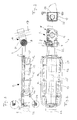
- the carrier part 2 is by means of Joint 3 about a pivot axis S relative to the holding element 1 swiveling.
- the holding element 1 is in use on a rod, for example a seat tube 17, attached.
- the carrier part 2 has a frame 12, which, as can be seen from FIG. 2, in the holding element 1 facing away area substantially U-shaped with a first leg 13 and a second leg 14.
- the both legs 13, 14 run in the longitudinal direction L of the Carrier largely parallel and approach in the Area of the holding element 1 to each other again.
- the Upper sides of the legs 13, 14 define the load receiving plane E.
- the legs 13, 14 are in Transverse direction connected by struts 15 which in the Front view in the longitudinal direction L are approximately U-shaped (see Fig. 3).
- a container 19 is arranged with a lid 24.
- the Container 19 is used for the protected reception of goods as well as splash protection on wet roads.
- the Cover 24 lies in level E and supports the load in addition, but can also be below.
- the container 19 has on its bottom clamping elements 21 which the Partially enclose struts 15 and so the Hold container 19 in place in the cage-like support part 2. With the help of the clamping elements 21, the container 19 on Carrier part are clipped in and again if necessary be clipped out.
- the container 19 in its Inside a receiving element 25 for a pump 35.
- the carrier part 2 also has the holding element on it 1 facing away from a bracket 20, in which a Taillight 26 can be inserted.
- the on the support part 2 load to be applied can for example by means of a Rubber straps 27 are attached.
- FIG 4 shows the luggage rack according to the invention in three different angle settings between the Holding element 1 and the carrier part 2. Is preferably the angle ⁇ between the holding element 1 and the Carrier part 2 in steps of 3 to 15, preferably 6 Degree adjustable.
- FIG. 5 shows an exploded view of the holding element 1, of the joint 3 and a part of the support part 2.
- Das Holding element 1 consists of a first holding part 28 and a second holding part 29, which by means of a Clamping mechanism 18 are clamped against each other and in assembled state a cylindrical receptacle 16 form for the seat tube 17.
- the recording 16 can Adaptation to different seat tube diameters Requirement can be reduced by means of insert clamps 31.
- the joint 3 comprises a first joint part 4, one second joint part 5 and a joint body 22.
- the carrier part 2 is fixed with the two Joint parts 4, 5 connected. These point to this Recesses 10.11 on the receiving ends of the Serve frame 12, which on the hinge parts 4,5 is attachable.
- the joint body 22 is by a semi-cylindrical extension on the second holding part 29 educated.
- the hinge parts 4, 5 are on their longitudinal axis A. rotationally symmetrical. They point along axis A. through bore 36 on the to perform a Fixing screw 23 is used.
- the joint parts 4, 5 are in designed essentially cylindrical, being at their the side facing the joint body 22 also one have cylindrical extension 38, 39. This is in Use case in a continuous further bore 37 in Articulated body used, which is about the same diameter as the extensions 38, 39 has. and.
- the angle ⁇ between the holding element 1 and the support part 2 adjustable adjustable is the angle ⁇ between the holding element 1 and the support part 2 adjustable adjustable.
- the fixing screw 23 dressed The fixing screw 23 penetrates in assembled state the holes 36, 37 of the Joint parts 4,5 and the joint body 22 and holes 30 in the ends of the carrier part 2. In this way at the same time determined the angular position and the Legs 13, 14 of the carrier part 2 are fastened to the joint 3.
- the holes 30 can also have another shape or it can each have a plurality of holes 30 on the legs 13, 14 be arranged so as to support part 2 in the longitudinal direction L to be able to adjust.
- the joint 3 is preferably made of glass fiber reinforced Plastic, e.g. PA 6.6.
- The is particularly preferably Fiber content 15 to 40%, especially 25%.
- the carrier part consists preferably of aluminum. This results in a high stability and strength of the joint 3 with little Weight.
- the free-floating support part can be 8 up to 10 kg.
- the teeth 8 arranged on the joint part extend radially from a first radius r1 starting up to a second radius r2.
- the teeth 8 are at equal angular intervals of approx. 6 ° along the Arranged circumferentially.
- FIG. 7b shows a detail from FIG. 6a for illustration a tooth 8; 7a shows an enlarged Side view in the radial direction of the joint part 4 Representation of the tooth profile.
- the tooth 8 is in radial direction of the joint part 4 always outwards wider.
- the teeth 8 have inclined slopes on both sides Flanks 32,33, which between the teeth 8 wedge-shaped depressions 34 with a depth T of preferably form 0.2 to 0.8 mm, preferably 0.5 mm.
- the Teeth 9 of the joint body 22 face one to the teeth 8 the joint parts 4.5 complementary shape.
- the profile of the Teeth 8.9 can also be designed differently, for example sawtooth-like or rectangular.
- One for Longitudinal axis L 'of the tooth asymmetrical flank shape, e.g. Sawtooth shape has the advantage that the joint in one Direction of rotation can be adjusted relatively easily while it locks well in the opposite direction.
Landscapes
- Engineering & Computer Science (AREA)
- Mechanical Engineering (AREA)
- Fittings On The Vehicle Exterior For Carrying Loads, And Devices For Holding Or Mounting Articles (AREA)
Applications Claiming Priority (2)
| Application Number | Priority Date | Filing Date | Title |
|---|---|---|---|
| CH11032002A CH695679A5 (de) | 2002-06-26 | 2002-06-26 | Sattelstützengepräckträger. |
| CH11032002 | 2002-06-26 |
Publications (1)
| Publication Number | Publication Date |
|---|---|
| EP1375320A1 true EP1375320A1 (fr) | 2004-01-02 |
Family
ID=29716494
Family Applications (1)
| Application Number | Title | Priority Date | Filing Date |
|---|---|---|---|
| EP03010557A Withdrawn EP1375320A1 (fr) | 2002-06-26 | 2003-05-12 | Porte-bagages attaché au tube porte-selle |
Country Status (2)
| Country | Link |
|---|---|
| EP (1) | EP1375320A1 (fr) |
| CH (1) | CH695679A5 (fr) |
Cited By (5)
| Publication number | Priority date | Publication date | Assignee | Title |
|---|---|---|---|---|
| EP1717137A1 (fr) | 2005-04-29 | 2006-11-02 | Buell Motorcycle Company | Support postérieur mobile pour une motocyclette |
| WO2009016666A1 (fr) * | 2007-08-02 | 2009-02-05 | Oxygen, S.P.A. | Porte-bagages avant pour motocyclettes |
| CN100475641C (zh) * | 2005-11-29 | 2009-04-08 | 极点股份有限公司 | 自行车车架的固定装置 |
| EP1650119A3 (fr) * | 2004-10-15 | 2010-05-19 | Batavus B.V. | Dispositif de fixation et porte-bagages avec ce dispositif de fixation |
| EP3643590A1 (fr) * | 2018-10-23 | 2020-04-29 | Eli International Enterpise Co, Ltd. | Structure réglable pour siège arrière de bicyclette |
Citations (7)
| Publication number | Priority date | Publication date | Assignee | Title |
|---|---|---|---|---|
| US4948020A (en) * | 1988-07-22 | 1990-08-14 | Smith Kenneth C | Bicycle carrier-seat cover device |
| DE9212659U1 (de) * | 1992-09-19 | 1993-01-28 | Prieschl, Herbert, 7117 Bretzfeld | Fahrradgepäckträger mit Stauraum fest montiert und abschließbar bzw. Fahrradgepäckträger mit abnehmbarem Taschenkörper zur Aufnahme von Gebrauchsgegenstände |
| WO1994011234A1 (fr) * | 1992-11-06 | 1994-05-26 | Ulrich Rindlisbacher | Dispositif a fixer sur le cadre d'un vehicule a deux roues |
| CH685757A5 (de) * | 1992-02-20 | 1995-09-29 | Nose Design Intelligence | Fahrradgepäckträger. |
| DE29711301U1 (de) * | 1997-06-28 | 1997-08-14 | Weiszdorn, Konrad, 74582 Gerabronn | Halterung für einen Autokindersitz |
| DE29715017U1 (de) * | 1997-08-22 | 1997-10-16 | Müller, Heiko, 64287 Darmstadt | Demontierbarer Fahrradgepäckträger |
| DE19853172A1 (de) * | 1998-11-19 | 2000-05-25 | Ulrich Artmann | Gepäckträger für ein Einspurfahrzeug |
-
2002
- 2002-06-26 CH CH11032002A patent/CH695679A5/de not_active IP Right Cessation
-
2003
- 2003-05-12 EP EP03010557A patent/EP1375320A1/fr not_active Withdrawn
Patent Citations (7)
| Publication number | Priority date | Publication date | Assignee | Title |
|---|---|---|---|---|
| US4948020A (en) * | 1988-07-22 | 1990-08-14 | Smith Kenneth C | Bicycle carrier-seat cover device |
| CH685757A5 (de) * | 1992-02-20 | 1995-09-29 | Nose Design Intelligence | Fahrradgepäckträger. |
| DE9212659U1 (de) * | 1992-09-19 | 1993-01-28 | Prieschl, Herbert, 7117 Bretzfeld | Fahrradgepäckträger mit Stauraum fest montiert und abschließbar bzw. Fahrradgepäckträger mit abnehmbarem Taschenkörper zur Aufnahme von Gebrauchsgegenstände |
| WO1994011234A1 (fr) * | 1992-11-06 | 1994-05-26 | Ulrich Rindlisbacher | Dispositif a fixer sur le cadre d'un vehicule a deux roues |
| DE29711301U1 (de) * | 1997-06-28 | 1997-08-14 | Weiszdorn, Konrad, 74582 Gerabronn | Halterung für einen Autokindersitz |
| DE29715017U1 (de) * | 1997-08-22 | 1997-10-16 | Müller, Heiko, 64287 Darmstadt | Demontierbarer Fahrradgepäckträger |
| DE19853172A1 (de) * | 1998-11-19 | 2000-05-25 | Ulrich Artmann | Gepäckträger für ein Einspurfahrzeug |
Cited By (5)
| Publication number | Priority date | Publication date | Assignee | Title |
|---|---|---|---|---|
| EP1650119A3 (fr) * | 2004-10-15 | 2010-05-19 | Batavus B.V. | Dispositif de fixation et porte-bagages avec ce dispositif de fixation |
| EP1717137A1 (fr) | 2005-04-29 | 2006-11-02 | Buell Motorcycle Company | Support postérieur mobile pour une motocyclette |
| CN100475641C (zh) * | 2005-11-29 | 2009-04-08 | 极点股份有限公司 | 自行车车架的固定装置 |
| WO2009016666A1 (fr) * | 2007-08-02 | 2009-02-05 | Oxygen, S.P.A. | Porte-bagages avant pour motocyclettes |
| EP3643590A1 (fr) * | 2018-10-23 | 2020-04-29 | Eli International Enterpise Co, Ltd. | Structure réglable pour siège arrière de bicyclette |
Also Published As
| Publication number | Publication date |
|---|---|
| CH695679A5 (de) | 2006-07-31 |
Similar Documents
| Publication | Publication Date | Title |
|---|---|---|
| EP2158120B1 (fr) | Patte de derailleur avec aide a l'installation | |
| DE4327971A1 (de) | Fahrradgepäckträger | |
| DE69522259T2 (de) | Lenkervorbau für zweiteilige Fahrradlenkstange | |
| DE102018116195B4 (de) | Gepäckträger-Anordnung mit Adapter | |
| EP1375320A1 (fr) | Porte-bagages attaché au tube porte-selle | |
| DE102007035135B3 (de) | Lastenträger zur Anbringung an der Heckklappe eines Fahrzeuges | |
| DE2621683A1 (de) | Vorrichtung zur befestigung von fahrraedern auf autodachtraegern | |
| DE7928391U1 (de) | Befestigung fuer fahrradlenker | |
| DE20220513U1 (de) | Fahrradsicherungseinrichtung und Fahrradsattelsicherungseinrichtung, insbesondere enthaltend eine derartige Fahrradsicherungseinrichtung | |
| DE20321195U1 (de) | Sattelstützengepäckträger | |
| DE202010016094U1 (de) | Fahrradtaschenhalter | |
| DE29605554U1 (de) | Heckgepäckträger für Kraftfahrzeuge | |
| DE19717570A1 (de) | Gepäckhaltevorrichtung für Fahrräder | |
| EP3722191A1 (fr) | Deux roues convertibles | |
| DE4320240A1 (de) | Diebstahlsicherung, insbesondere für Fahrräder | |
| DE9216759U1 (de) | Vorrichtung zum Befestigen von Fahrrädern auf einem Dach eines Kraftfahrzeuges | |
| EP1067041B1 (fr) | Support de roue arrière pour véhicule à deux roues | |
| DE202005019173U1 (de) | Halterung zum lösbaren Anbringen eines Behältnisses an der Lenkstange eines Fahrrades | |
| EP0708015A2 (fr) | Porte-bagages universel pour des bicyclettes | |
| DE4339740C1 (de) | Gepäckträger für Zwei- oder Mehrräder, insbesondere Fahrräder | |
| DE102023110676A1 (de) | Wandhalterung | |
| EP1040989A2 (fr) | Porte-bagages pour véhicule | |
| DE202023000572U1 (de) | Universelle Sicherungssattelstange | |
| CH671742A5 (en) | Accessory fastener for bicycle frames - with clamp shoes with concave clamp surface for tubing | |
| DE483863C (de) | Vorrichtung zum Anschliessen von Fahrraedern |
Legal Events
| Date | Code | Title | Description |
|---|---|---|---|
| PUAI | Public reference made under article 153(3) epc to a published international application that has entered the european phase |
Free format text: ORIGINAL CODE: 0009012 |
|
| AK | Designated contracting states |
Kind code of ref document: A1 Designated state(s): AT BE BG CH CY CZ DE DK EE ES FI FR GB GR HU IE IT LI LU MC NL PT RO SE SI SK TR |
|
| AX | Request for extension of the european patent |
Extension state: AL LT LV MK |
|
| 17P | Request for examination filed |
Effective date: 20040630 |
|
| AKX | Designation fees paid |
Designated state(s): AT BE BG CH CY CZ DE DK EE ES FI FR GB GR HU IE IT LI LU MC NL PT RO SE SI SK TR |
|
| STAA | Information on the status of an ep patent application or granted ep patent |
Free format text: STATUS: THE APPLICATION HAS BEEN WITHDRAWN |
|
| 18W | Application withdrawn |
Effective date: 20060221 |