EP1375845A1 - Cam shaft less valve actuator with position signal device for valve stem - Google Patents
Cam shaft less valve actuator with position signal device for valve stem Download PDFInfo
- Publication number
- EP1375845A1 EP1375845A1 EP03011134A EP03011134A EP1375845A1 EP 1375845 A1 EP1375845 A1 EP 1375845A1 EP 03011134 A EP03011134 A EP 03011134A EP 03011134 A EP03011134 A EP 03011134A EP 1375845 A1 EP1375845 A1 EP 1375845A1
- Authority
- EP
- European Patent Office
- Prior art keywords
- plunger
- target
- actuator
- assembly according
- connecting layer
- Prior art date
- Legal status (The legal status is an assumption and is not a legal conclusion. Google has not performed a legal analysis and makes no representation as to the accuracy of the status listed.)
- Withdrawn
Links
- 229910000679 solder Inorganic materials 0.000 claims abstract description 14
- 229920001971 elastomer Polymers 0.000 claims abstract description 5
- 239000006260 foam Substances 0.000 claims abstract description 5
- 239000000806 elastomer Substances 0.000 claims abstract description 4
- 230000001133 acceleration Effects 0.000 claims abstract description 3
- 238000002485 combustion reaction Methods 0.000 claims description 8
- 238000005476 soldering Methods 0.000 claims description 8
- 239000000853 adhesive Substances 0.000 claims description 7
- 230000001070 adhesive effect Effects 0.000 claims description 7
- 238000004026 adhesive bonding Methods 0.000 claims description 6
- 239000011148 porous material Substances 0.000 claims description 3
- 230000005540 biological transmission Effects 0.000 claims description 2
- 239000000463 material Substances 0.000 description 9
- 229910052802 copper Inorganic materials 0.000 description 6
- 239000010949 copper Substances 0.000 description 6
- RYGMFSIKBFXOCR-UHFFFAOYSA-N Copper Chemical compound [Cu] RYGMFSIKBFXOCR-UHFFFAOYSA-N 0.000 description 5
- 229910045601 alloy Inorganic materials 0.000 description 4
- 239000000956 alloy Substances 0.000 description 4
- PXHVJJICTQNCMI-UHFFFAOYSA-N Nickel Chemical compound [Ni] PXHVJJICTQNCMI-UHFFFAOYSA-N 0.000 description 3
- 230000000694 effects Effects 0.000 description 3
- 239000004604 Blowing Agent Substances 0.000 description 2
- 229910000640 Fe alloy Inorganic materials 0.000 description 2
- BQCADISMDOOEFD-UHFFFAOYSA-N Silver Chemical compound [Ag] BQCADISMDOOEFD-UHFFFAOYSA-N 0.000 description 2
- 229910000831 Steel Inorganic materials 0.000 description 2
- 238000013016 damping Methods 0.000 description 2
- XEEYBQQBJWHFJM-UHFFFAOYSA-N iron Substances [Fe] XEEYBQQBJWHFJM-UHFFFAOYSA-N 0.000 description 2
- 238000004519 manufacturing process Methods 0.000 description 2
- 229910000734 martensite Inorganic materials 0.000 description 2
- 229910052709 silver Inorganic materials 0.000 description 2
- 239000004332 silver Substances 0.000 description 2
- 239000010959 steel Substances 0.000 description 2
- 238000005452 bending Methods 0.000 description 1
- 230000015572 biosynthetic process Effects 0.000 description 1
- 229910052804 chromium Inorganic materials 0.000 description 1
- 230000006835 compression Effects 0.000 description 1
- 238000007906 compression Methods 0.000 description 1
- 238000000635 electron micrograph Methods 0.000 description 1
- 239000000696 magnetic material Substances 0.000 description 1
- 229910052759 nickel Inorganic materials 0.000 description 1
- 229910052698 phosphorus Inorganic materials 0.000 description 1
- 239000004033 plastic Substances 0.000 description 1
- 229920003023 plastic Polymers 0.000 description 1
- 229920002635 polyurethane Polymers 0.000 description 1
- 239000004814 polyurethane Substances 0.000 description 1
- 239000003380 propellant Substances 0.000 description 1
- 230000035945 sensitivity Effects 0.000 description 1
- 230000035939 shock Effects 0.000 description 1
- 230000036962 time dependent Effects 0.000 description 1
Images

Classifications
-
- F—MECHANICAL ENGINEERING; LIGHTING; HEATING; WEAPONS; BLASTING
- F01—MACHINES OR ENGINES IN GENERAL; ENGINE PLANTS IN GENERAL; STEAM ENGINES
- F01L—CYCLICALLY OPERATING VALVES FOR MACHINES OR ENGINES
- F01L9/00—Valve-gear or valve arrangements actuated non-mechanically
- F01L9/20—Valve-gear or valve arrangements actuated non-mechanically by electric means
-
- F—MECHANICAL ENGINEERING; LIGHTING; HEATING; WEAPONS; BLASTING
- F01—MACHINES OR ENGINES IN GENERAL; ENGINE PLANTS IN GENERAL; STEAM ENGINES
- F01L—CYCLICALLY OPERATING VALVES FOR MACHINES OR ENGINES
- F01L9/00—Valve-gear or valve arrangements actuated non-mechanically
- F01L9/20—Valve-gear or valve arrangements actuated non-mechanically by electric means
- F01L9/21—Valve-gear or valve arrangements actuated non-mechanically by electric means actuated by solenoids
- F01L2009/2167—Sensing means
- F01L2009/2169—Position sensors
-
- F—MECHANICAL ENGINEERING; LIGHTING; HEATING; WEAPONS; BLASTING
- F01—MACHINES OR ENGINES IN GENERAL; ENGINE PLANTS IN GENERAL; STEAM ENGINES
- F01L—CYCLICALLY OPERATING VALVES FOR MACHINES OR ENGINES
- F01L2301/00—Using particular materials
-
- F—MECHANICAL ENGINEERING; LIGHTING; HEATING; WEAPONS; BLASTING
- F01—MACHINES OR ENGINES IN GENERAL; ENGINE PLANTS IN GENERAL; STEAM ENGINES
- F01L—CYCLICALLY OPERATING VALVES FOR MACHINES OR ENGINES
- F01L2303/00—Manufacturing of components used in valve arrangements
-
- F—MECHANICAL ENGINEERING; LIGHTING; HEATING; WEAPONS; BLASTING
- F01—MACHINES OR ENGINES IN GENERAL; ENGINE PLANTS IN GENERAL; STEAM ENGINES
- F01L—CYCLICALLY OPERATING VALVES FOR MACHINES OR ENGINES
- F01L2800/00—Methods of operation using a variable valve timing mechanism
Definitions
- the invention relates to an assembly consisting of an oscillating moving plunger and a target attached to the outer periphery of the plunger for generating position signals, the target in a circumferential groove in the Tappet added and manufactured by means of soldering or gluing Connection layer is connected to the plunger.
- the invention further relates to a camshaft-less actuator containing the assembly for actuation of a lift valve of an internal combustion engine.
- the camshaftless valve trains are often electromagnetic Actuators. So that the plunger can be positioned exactly, it is necessary to determine its position as precisely as possible. So-called targets are used for this the plungers provided, the positions of which are designed accordingly Sensors can be determined. So far, so-called Copper targets used. For this purpose, a groove in the ram is filled with copper. Then the plunger is usually machined on the outside so that the Copper-filled area without a step into the adjacent outer surface of the plunger transforms.
- an actuator in which The outer circumference of the plunger is at least simply slotted, as a separate, Prefabricated part trained target ring is attached, which is made of one material Fe-based or made of a ferritic material and in one on the plunger formed circumferential groove is inserted.
- a target ring based on Fe or consists of a ferritic material a sensor can be used that works with lower frequencies than with a target made of copper.
- the invention provides an actuator that operates largely without interference signals, which enables an exact position determination by the assigned sensor and thus the life of the valve train via improved control elevated.
- an assembly is provided according to the invention, which consists of a oscillating plunger and one on the outer periphery of the plunger fixed target for generating position signals, especially for a camshaftless actuator of an internal combustion engine, the target in a circumferential groove in the plunger and by means of soldering or Adhesive connection layer produced is connected to the plunger, and the is characterized in that the connection layer to the mechanical Decoupling of the plunger and the target is designed to be force-isolating.
- connection layer is achieved by vibrations and other external forces occurring no longer from the ram to the Target transferred but already taken up by the connection layer and be absorbed.
- the occurrence of interference signals by a time-dependent change of the magnetic properties of the target safely prevented and the target mechanically and magnetically decoupled from the plunger.
- the force-insulating design of the connection layer is preferred thereby achieves that the connecting layer has a porosity, the porosity, measured as the ratio between pore volume and sample volume, preferred is at least about 10%, particularly preferably at least about 30%. Due to the porosity introduced into the connection layer, in particular simply increases the elasticity of the layer and a vibration-damping effect can be achieved.
- the introduction of a porosity into the connection layer for example, by using Blowing agents or sacrificial materials during the manufacture of the solder or Adhesive connection, as in principle in the manufacture of Foams is known.
- the assembly according to the invention particularly preferably has a Connection layer on which the target against the transmission of train and Compressive stresses isolated.
- the invention also relates to a camshaftless actuator for Actuation of a lift valve of an internal combustion engine, with an oscillating one moved, coupled to the stroke valve tappet, the inventive Contains assembly.
- the actuator is preferably an electromagnetic one Actuator with one or two coils.
- the plunger forms the anchor shaft. This actuates the valve stem and is coupled to the valve stem or possibly even connected in one piece.
- a sensor can be located in the actuator near the preferably ring-shaped target be provided, the location, speed or acceleration of the Target rings and thus the ram detected.
- the target ring can consist of two or more in a known manner adjacent ring segments, preferably circular ring segments, be composed, which can form separate, prefabricated parts.
- This Embodiment offers the advantage that the target ring is not when fastening must be elastically deformed, but that the segments from radially outside of the seat on the plunger is simply inserted into the circumferential groove and by means of the solder or adhesive connection can be attached.
- the target preferably consists of a ferritic iron alloy, steel or another ferritic material, such as that from DE 201 15 060 U1 is known.
- ferritic alloys allows the exact Position determination and thus increases the signal accuracy.
- the plunger or Anchor shaft can be made of non-magnetic, martensitic or austenitic Materials or alloys are formed. Because of their stability and Austenitic alloys are particularly preferred for mechanical strength.
- the invention provides an actuator with one by mechanical and magnetic decoupling target free of interference, by the signal quality and the accuracy of the position determination clearly can be increased.
- FIG. 1 shows an internal combustion engine 10 in the region of the cylinder head shown, in which the lift valve 12 by a camshaft-less valve train in Form of an electromagnetic actuator 14 is actuated.
- the actuator 14 comprises two electromagnets 16, 18 through which an armature or, more generally said a plunger 20 extends at its lower end with the Lift valve stem 22 is connected so that the axial, oscillating movement of the Tappet 20 immediately corresponding movement of the lift valve 12th causes.
- the axial movement of the plunger 20 is to be path-controlled, which is why the position of the plunger must be determined as precisely and quickly as possible.
- a sensor 24 surrounding the plunger is for determining the position of the plunger 20 provided. Radially inward of the sensor 24 is a target ring 26 in one Circumferential groove 27 fastened in the plunger 20 without play and gap. The sensor 24 determines the position of the target ring 26 and thus the plunger 20 and Lift valve 22.
- the target ring 26 is preferably made of an iron alloy, steel or a ferritic material formed. Alternatively, conventional ones can also be used Copper targets are used. In the embodiment shown, the Target ring is a separate, prefabricated part that can be glued or attached to the ram Soldering is attached.
- the plunger or anchor shaft 20 preferably consists of a austenitic alloy. But it can also be martensitic or non-magnetic Materials are used.
- the geometry of the target ring 26 and that of the target ring Circumferential groove 27 can be freely selected, as is the case, for example, in DE 201 15 060 U1 is described.
- the target ring 26 preferably consists of two or more Ring segments that simply from the radially outside on the plunger, more precisely in the circumferential groove forming sections of the outer circumference are used.
- the Segments, more precisely cylinder half shells, are in the circumferential groove and if necessary also attached to each other by soldering or gluing.
- the Dimensions of the segments are matched to that of the circumferential groove, so that as radially and circumferentially as possible no gap or between the segments Shock occurs.
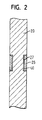
- plunger or anchor shaft 20 and target ring 26 is in the figure 2 shown in detail. It can be seen in particular that the plunger 20 and the in the circumferential groove 27 in the ram inserted target ring 26 by means of a soldering or bonding layer 40 produced by adhesive bonding.
- the connecting layer 40 is for the mechanical decoupling of the plunger 20 and of the target ring 26 is designed to be force-isolating. This means that the Connection layer 40 in particular that caused by vibrations of the plunger caused compressive and tensile stresses, which are no longer be transferred to the target ring 26.
- connection layer 40 is one porous solder joint with a porosity of at least 10%, measured as Pore volume in relation to the volume of the sample.
- the solder joint can by soldering the plunger 20 and the target ring 26 with conventional, mostly silver-containing high-temperature solders are produced that additionally Contain sacrificial materials or propellants to create porosity. about the proportion of the sacrificial materials or the blowing agents can be the porosity of the connection layer can be set in a targeted manner, with the porosity should be at least 10%. Below this limit is the force isolating one Effect of the connection layer is no longer guaranteed.
- connection layer 40 is at least 30%, which makes the Elasticity of the connection layer and its vibration-damping effect can also be increased.
- connection layer made of an elastomer, i.e. a plastic Rubber elasticity. It is also conceivable for gluing the Tappet 20 and the target 26 to use a foam, for example based on polyurethane, which creates a porous, closed-cell or can form open-cell connection layer 40.
- Test trials with the assembly according to the invention in one camshaftless valve train resulted in a significant reduction in Interference signals at the sensor and thus an improved accuracy of Determining the position of the ram. Ultimately, this will result in improved control of the valve train, which also increases the life of the component.
Landscapes
- Engineering & Computer Science (AREA)
- Mechanical Engineering (AREA)
- General Engineering & Computer Science (AREA)
- Valve Device For Special Equipments (AREA)
- Valve-Gear Or Valve Arrangements (AREA)
Abstract
Description
Die Erfindung betrifft eine Baugruppe bestehend aus einem oszillierend bewegten Stößel und einem auf dem Außenumfang des Stößels befestigten Target zur Erzeugung von Positionssignalen, wobei das Target in einer Umfangsnut im Stößel aufgenommen und mittels einer durch Löten oder Kleben hergestellten Verbindungsschicht mit dem Stößel verbunden ist. Ferner betrifft die Erfindung einen die Baugruppe enthaltenden nockenwellenlosen Aktuator zur Betätigung eines Hubventils einer Brennkraftmaschine.The invention relates to an assembly consisting of an oscillating moving plunger and a target attached to the outer periphery of the plunger for generating position signals, the target in a circumferential groove in the Tappet added and manufactured by means of soldering or gluing Connection layer is connected to the plunger. The invention further relates to a camshaft-less actuator containing the assembly for actuation of a lift valve of an internal combustion engine.
Häufig sind die nockenwellenlosen Ventiltriebe elektromagnetische Aktuatoren. Damit der Stößel exakt positioniert werden kann, ist es erforderlich, seine Lage möglichst exakt zu bestimmen. Hierzu werden sogenannte Targets an den Stößeln vorgesehen, deren Positionen mittels entsprechend ausgelegter Sensoren bestimmt werden können. Bislang werden hauptsächlich sogenannte Kupfertargets verwendet. Dazu wird eine Nut im Stößel mit Kupfer gefüllt. Anschließend wird der Stößel üblicherweise außenseitig bearbeitet, damit der mit Kupfer gefüllte Bereich absatzlos in die angrenzende Außenfläche des Stößels übergeht.The camshaftless valve trains are often electromagnetic Actuators. So that the plunger can be positioned exactly, it is necessary to determine its position as precisely as possible. So-called targets are used for this the plungers provided, the positions of which are designed accordingly Sensors can be determined. So far, so-called Copper targets used. For this purpose, a groove in the ram is filled with copper. Then the plunger is usually machined on the outside so that the Copper-filled area without a step into the adjacent outer surface of the plunger transforms.
Aus der DE 201 15 060 U1 ist ein Aktuator bekannt, bei dem auf dem Außenumfang des Stößels ein wenigstens einfach geschlitzter, als separates, vorgefertigtes Teil ausgebildeter Targetring befestigt ist, der aus einem Werkstoff auf Fe-Basis oder aus einem ferritischen Werkstoff besteht und in eine am Stößel gebildete Umfangsnut eingelegt ist. Durch einen Targetring, der auf Fe-Basis oder aus einem ferritischen Werkstoff besteht, kann ein Sensor verwendet werden, der mit niedrigeren Frequenzen als bei einem Target aus Kupfer arbeitet.From DE 201 15 060 U1 an actuator is known in which The outer circumference of the plunger is at least simply slotted, as a separate, Prefabricated part trained target ring is attached, which is made of one material Fe-based or made of a ferritic material and in one on the plunger formed circumferential groove is inserted. Through a target ring based on Fe or consists of a ferritic material, a sensor can be used that works with lower frequencies than with a target made of copper.
Durch die Verwendung von niedrigeren Frequenzen zur Positionsbestimmung des Stößels ist allerdings auch die Empfindlichkeit der Sensoren gegenüber Störsignalen größer. Untersuchungen haben ergeben, daß die schnelle oszillierende Bewegung der Stößel zu Abknickschwingungen führt, die insbesondere im dem durch die Umfangsnut ohnehin mechanisch geschwächten Targetbereich auftreten. Durch die Abknickschwingungen werden Druck- und Zugspannungen vom Stößel auf das Target übertragen, die die magnetischen Eigenschaften des Targets zeitabhängig ändern und so zu Störsignalen führen.By using lower frequencies for position determination of the plunger is also the sensitivity of the sensors Interference signals larger. Studies have shown that the rapid oscillating movement of the plunger leads to buckling vibrations especially in the one that is already mechanically weakened by the circumferential groove Target area occur. The bending vibrations cause pressure and Tensile stresses are transferred from the plunger to the target, which the magnetic Change the properties of the target as a function of time and thus lead to interference signals.
Die Erfindung schafft einen weitgehend störsignalfrei arbeitenden Aktuator, der eine exakte Positionsbestimmung durch den zugeordneten Sensor ermöglicht und so über eine verbesserte Steuerung auch die Lebensdauer des Ventiltriebs erhöht. Hierzu wird erfindungsgemäß eine Baugruppe bereitgestellt, die aus einem oszillierend bewegten Stößel und einem auf dem Außenumfang des Stößels befestigten Target zur Erzeugung von Positionssignalen besteht, insbesondere für einen nockenwellenlosen Aktuator einer Brennkraftmaschine, wobei das Target in einer Umfangsnut im Stößel aufgenommen und mittels einer durch Löten oder Kleben hergestellten Verbindungsschicht mit dem Stößel verbunden ist, und die dadurch gekennzeichnet ist, daß die Verbindungsschicht zur mechanischen Entkopplung des Stößels und des Targets kraftisolierend ausgebildet ist.The invention provides an actuator that operates largely without interference signals, which enables an exact position determination by the assigned sensor and thus the life of the valve train via improved control elevated. For this purpose, an assembly is provided according to the invention, which consists of a oscillating plunger and one on the outer periphery of the plunger fixed target for generating position signals, especially for a camshaftless actuator of an internal combustion engine, the target in a circumferential groove in the plunger and by means of soldering or Adhesive connection layer produced is connected to the plunger, and the is characterized in that the connection layer to the mechanical Decoupling of the plunger and the target is designed to be force-isolating.
Herkömmliche Löt- oder Klebeverbindungen zur Verbindung des Targets und des Stößels sind üblicherweise massive, harte und im wesentlichen unelastische Schichten, die keine Lasten aufnehmen können. Durch die kraftisolierende Ausbildung der Verbindungsschicht wird erreicht, daß die durch Schwingungen und sonstige äußere Einflüsse auftretenden Kräfte nicht mehr vom Stößel auf das Target übertragen sondern bereits von der Verbindungsschicht aufgenommen und absorbiert werden. Damit wird das Auftreten von Störsignalen durch eine zeitabhängige Änderung der magnetischen Eigenschaften des Targets sicher verhindert und das Target mechanisch und magnetisch vom Stößel entkoppelt.Conventional solder or adhesive connections for connecting the target and the Tappets are usually massive, hard and essentially inelastic Layers that cannot take loads. Due to the force isolating Formation of the connection layer is achieved by vibrations and other external forces occurring no longer from the ram to the Target transferred but already taken up by the connection layer and be absorbed. The occurrence of interference signals by a time-dependent change of the magnetic properties of the target safely prevented and the target mechanically and magnetically decoupled from the plunger.
Die kraftisolierende Ausbildung der Verbindungsschicht wird bevorzugt dadurch erreicht, daß die Verbindungsschicht eine Porosität aufweist, wobei die Porosität, gemessen als Verhältnis zwischen Porenvolumen und Probenvolumen, bevorzugt mindestens etwa 10 %, besonders bevorzugt mindestens etwa 30 %, beträgt. Durch die in die Verbindungsschicht eingebrachte Porosität kann in besonders einfacher Weise die Elastizität der Schicht erhöht und eine schwingungsdämpfende Wirkung erzielt werden. Das Einbringen einer Porosität in die Verbindungsschicht kann beispielsweise durch die Verwendung von Treibmitteln oder Opfermaterialien während der Herstellung der Löt- oder Klebeverbindung erfolgen, wie dies im Prinzip bei der Herstellung von Schaumstoffen bekannt ist.The force-insulating design of the connection layer is preferred thereby achieves that the connecting layer has a porosity, the porosity, measured as the ratio between pore volume and sample volume, preferred is at least about 10%, particularly preferably at least about 30%. Due to the porosity introduced into the connection layer, in particular simply increases the elasticity of the layer and a vibration-damping effect can be achieved. The introduction of a porosity into the connection layer, for example, by using Blowing agents or sacrificial materials during the manufacture of the solder or Adhesive connection, as in principle in the manufacture of Foams is known.
Besonders bevorzugt weist die erfindungsgemäße Baugruppe eine Verbindungsschicht auf, die das Target gegen die Übertragung von Zug- und Druckspannungen isoliert.The assembly according to the invention particularly preferably has a Connection layer on which the target against the transmission of train and Compressive stresses isolated.
Als Verbindungsschicht kann insbesondere ein bevorzugt silberhaltiges oder nickelhaltiges Hochtemperaturlot mit in das Lot eingebrachter Porosität verwendet werden, wobei der Lötbereich bevorzugt zwischen 900°C und 1100°C liegt. Besonders bevorzugt ist ein Lot auf der Grundlage von Ni, mit weiteren Anteilen an Cu, Cr und P. Mit dieser Lotverbindung wird eine besonders haltbare und haftfeste Verbindung zwischen dem Stößel und dem Target erreicht. Alternativ dazu ist die Verwendung einer aus einem Elastomer oder einem offen- bzw. geschlossenzelligen Schaumstoff gebildeten Klebeverbindung denkbar.A preferably silver-containing or Nickel-containing high-temperature solder with porosity introduced into the solder be used, the soldering range preferably between 900 ° C and 1100 ° C. lies. A solder based on Ni, with others, is particularly preferred Shares in Cu, Cr and P. This solder connection makes it particularly durable and a firm connection between the plunger and the target is achieved. Alternatively, the use of an elastomer or an open or closed-cell foam adhesive bond formed.
Gegenstand der Erfindung ist ferner ein nockenwellenloser Aktuator zur Betätigung eines Hubventils einer Brennkraftmaschine, mit einem oszillierend bewegten, mit dem Hubventil gekoppelten Stößel, der die erfindungsgemäße Baugruppe enthält. Vorzugsweise ist der Aktuator ein elektromagnetischer Aktuator mit einer oder zwei Spulen. Der Stößel bildet den Ankerschaft. Dieser betätigt den Ventilschaft und ist mit dem Ventilschaft gekoppelt oder gegebenenfalls sogar einstückig verbunden.The invention also relates to a camshaftless actuator for Actuation of a lift valve of an internal combustion engine, with an oscillating one moved, coupled to the stroke valve tappet, the inventive Contains assembly. The actuator is preferably an electromagnetic one Actuator with one or two coils. The plunger forms the anchor shaft. This actuates the valve stem and is coupled to the valve stem or possibly even connected in one piece.
In dem Aktuator kann nahe des bevorzugt ringförmigen Targets ein Sensor vorgesehen sein, der die Lage, die Geschwindigkeit oder die Beschleunigung des Targetrings und damit des Stößels erfasst.A sensor can be located in the actuator near the preferably ring-shaped target be provided, the location, speed or acceleration of the Target rings and thus the ram detected.
Der Targetring kann in bekannter Weise aus zwei oder mehr aneinandergrenzenden Ringsegmenten, vorzugsweise Kreisringsegmenten, zusammengesetzt sein, die separate, vorgefertigte Teile bilden können. Diese Ausführungsform bietet den Vorteil, daß der Targetring nicht beim Befestigen elastisch verformt werden muß, sondern daß die Segmente von radial außerhalb des Sitzes am Stößel einfach in die Umfangsnut eingelegt und mittels der Löt- oder Klebeverbindung befestigt werden können.The target ring can consist of two or more in a known manner adjacent ring segments, preferably circular ring segments, be composed, which can form separate, prefabricated parts. This Embodiment offers the advantage that the target ring is not when fastening must be elastically deformed, but that the segments from radially outside of the seat on the plunger is simply inserted into the circumferential groove and by means of the solder or adhesive connection can be attached.
Das Target besteht bevorzugt aus einer ferritischen Eisenlegierung, Stahl oder einem anderen ferritischen Material, wie dies beispielsweise aus der DE 201 15 060 U1 bekannt ist. Der Einsatz von ferritischen Legierungen erlaubt die genaue Positionsbestimmung und erhöht so die Signalgenauigkeit. Der Stößel bzw. Ankerschaft kann aus nicht-magnetischen, martensitischen oder austenitischen Werkstoffen bzw. Legierungen gebildet sein. Aufgrund ihrer Stabilität und mechanischen Belastbarkeit sind austenitische Legierungen besonders bevorzugt.The target preferably consists of a ferritic iron alloy, steel or another ferritic material, such as that from DE 201 15 060 U1 is known. The use of ferritic alloys allows the exact Position determination and thus increases the signal accuracy. The plunger or Anchor shaft can be made of non-magnetic, martensitic or austenitic Materials or alloys are formed. Because of their stability and Austenitic alloys are particularly preferred for mechanical strength.
Die Erfindung schafft, zusammenfassend gesagt, einen Aktuator mit einem durch mechanische und magnetische Entkoppelung störsignalfreien Target, durch das die Signalqualität und die Genauigkeit der Positionsbestimmung deutlich gesteigert werden kann.In summary, the invention provides an actuator with one by mechanical and magnetic decoupling target free of interference, by the signal quality and the accuracy of the position determination clearly can be increased.
Weitere Merkmale und Vorteile der Erfindung ergeben sich aus der
nachfolgenden Beschreibung und aus den nachfolgenden Zeichnungen, auf die
Bezug genommen wird. In den Zeichnungen zeigen:
In Figur 1 ist eine Brennkraftmaschine 10 im Bereich des Zylinderkopfes
dargestellt, bei der das Hubventil 12 durch einen nockenwellenlosen Ventiltrieb in
Form eines elektromagnetischen Aktuators 14 betätigt wird. Der Aktuator 14
umfaßt zwei Elektromagnete 16, 18, durch die sich ein Anker oder, allgemeiner
gesagt, ein Stößel 20 erstreckt, der an seinem unteren Ende mit dem
Hubventilschaft 22 verbunden ist, so daß die axiale, oszillierende Bewegung des
Stößels 20 unmittelbar eine entsprechende Bewegung des Hubventils 12
hervorruft. Die Axialbewegung des Stößels 20 soll weggesteuert erfolgen,
weshalb die Lage des Stößels möglichst exakt und schnell ermittelt werden muß.
Ein den Stößel umgebender Sensor 24 ist für die Positionsbestimmung des Stößels
20 vorgesehen. Radial einwärts des Sensors 24 ist ein Targetring 26 in einer
Umfangsnut 27 im Stößel 20 spiel- und spaltfrei befestigt. Der Sensor 24
bestimmt die Lage des Targetrings 26 und damit des Stößels 20 und des
Hubventils 22.1 shows an
Der Targetring 26 ist bevorzugt aus einer Eisenlegierung, Stahl oder einem
ferritischen Werkstoff gebildet. Alternativ dazu können auch herkömmliche
Kupfertargets verwendet werden. Bei der gezeigten Ausführungsform ist der
Targetring ein separates, vorgefertigtes Teil, das am Stößel durch Kleben oder
Löten befestigt wird. Der Stößel oder Ankerschaft 20 besteht bevorzugt aus einer
austenitischen Legierung. Es können aber auch martensitische oder nichtmagnetische
Werkstoffe verwendet werden. The
In Figur 1 ist noch zu erkennen, daß das Hubventil 12 durch eine an einem
Federteller 28, welcher am Ventilschaft 22 befestigt ist, angreifende Druckfeder
30 in die gezeigte Schließstellung gedrückt wird.In Figure 1 it can still be seen that the
Die Geometrie des Targetrings 26 und der den Targetring aufnehmenden
Umfangsnut 27 ist frei wählbar, wie dies beispielsweise in der DE 201 15 060 U1
beschrieben ist. Bevorzugt besteht der Targetring 26 aus zwei oder mehr
Ringsegmenten, die einfach von radial außen auf den Stößel, genauer gesagt in die
den Außenumfang abschnittsweise bildende Umfangsnut eingesetzt werden. Die
Segmente, genauer gesagt Zylinderhalbschalen, sind in der Umfangsnut und
gegebenenfalls auch aneinander durch Löten oder Kleben befestigt. Die
Abmessungen der Segmente sind auf die der Umfangsnut abgestimmt, so daß
möglichst radial und umfangsmäßig zwischen den Segmenten kein Spalt oder
Stoß auftritt.The geometry of the
Die Baugruppe aus Stößel bzw. Ankerschaft 20 und Targetring 26 ist in Figur
2 im Detail dargestellt. Zu erkennen ist insbesondere, daß der Stößel 20 und der in
die Umfangsnut 27 im Stößel eingelegte Targetring 26 mittels einer durch Löten
oder Kleben hergestellten Verbindungsschicht 40 miteinander verbunden sind.
Die Verbindungsschicht 40 ist zur mechanischen Entkopplung des Stößels 20 und
des Targetrings 26 kraftisolierend ausgebildet. Dies bedeutet, daß die
Verbindungsschicht 40 insbesondere die durch Schwingungen des Stößels
verursachten Druck- und Zugspannungen aufnehmen kann, die somit nicht mehr
auf den Targetring 26 übertragen werden.The assembly of plunger or
Bei einer bevorzugten Ausführungsform ist die Verbindungsschicht 40 eine
poröse Lötverbindung mit einer Porosität von mindestens 10%, gemessen als
Porenvolumen im Verhältnis zum Volumen der Probe. Die Lötverbindung kann
durch Verlöten des Stößels 20 und des Targetrings 26 mit herkömmlichen, meist
silberhaltigen Hochtemperaturloten hergestellt werden, die zusätzlich
Opfermaterialien oder Treibmittel zur Erzeugung der Porosität enthalten. Über
den Anteil der Opfermaterialien bzw. der Treibmittel kann die Porosität der
Verbindungsschicht zielgerichtet eingestellt werden, wobei die Porosität
mindestens 10% betragen sollte. Unterhalb dieser Grenze ist die kraftisolierende
Wirkung der Verbindungsschicht nicht mehr gewährleistet. Bevorzugt beträgt die
Porosität der Verbindungsschicht 40 jedoch wenigstens 30%, wodurch die
Elastizität der Verbindungsschicht sowie deren schwingungsdämpfende Wirkung
zusätzlich erhöht werden. Alternativ dazu kann eine durch Kleben hergestellte
Verbindungsschicht aus einem Elastomer, das heißt einem Kunststoff mit
Gummielastizität, hergestellt sein. Des weiteren ist denkbar, für das Verkleben des
Stößels 20 und des Targets 26 einen Schaumstoff zu verwenden, beispielsweise
auf der Grundlage von Polyurethan, wodurch sich eine poröse, geschlossenzellige
oder offenzellige Verbindungsschicht 40 ausbilden kann.In a preferred embodiment, the connection layer 40 is one
porous solder joint with a porosity of at least 10%, measured as
Pore volume in relation to the volume of the sample. The solder joint can
by soldering the
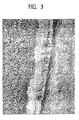
In Figur 3 ist der Schliff eines Querschnitts durch den Stößel 20 im Bereich
des Targetrings 26 in zweihundertfacher Vergrößerung gezeigt. Zu erkennen ist,
daß die Lötverbindung zwischen Stößel und Targetring eine durch Mikroporen,
Fehlstellen und zum Teil Anrisse im Mikroporenbereich verursachte Porosität
aufweist. Dennoch ist eine sichere Verbindung zwischen Schaft und Targetring
gewährleistet.In Figure 3, the grinding of a cross section through the
Testversuche mit der erfindungsgemäßen Baugruppe in einem nockenwellenlosen Ventiltrieb ergaben eine wesentliche Reduzierung der Störsignale am Sensor und damit eine verbesserte Genauigkeit der Positionsbestimmung des Stößels. Letztlich wird somit eine verbesserte Steuerung des Ventiltriebs ermöglicht, die auch die Lebensdauer des Bauteils erhöht.Test trials with the assembly according to the invention in one camshaftless valve train resulted in a significant reduction in Interference signals at the sensor and thus an improved accuracy of Determining the position of the ram. Ultimately, this will result in improved control of the valve train, which also increases the life of the component.
Claims (10)
Applications Claiming Priority (2)
| Application Number | Priority Date | Filing Date | Title |
|---|---|---|---|
| DE20209369U DE20209369U1 (en) | 2002-06-17 | 2002-06-17 | Assembly for an actuator and the assembly containing the camshaft-less actuator |
| DE20209369U | 2002-06-17 |
Publications (1)
| Publication Number | Publication Date |
|---|---|
| EP1375845A1 true EP1375845A1 (en) | 2004-01-02 |
Family
ID=7972250
Family Applications (1)
| Application Number | Title | Priority Date | Filing Date |
|---|---|---|---|
| EP03011134A Withdrawn EP1375845A1 (en) | 2002-06-17 | 2003-05-23 | Cam shaft less valve actuator with position signal device for valve stem |
Country Status (2)
| Country | Link |
|---|---|
| EP (1) | EP1375845A1 (en) |
| DE (1) | DE20209369U1 (en) |
Families Citing this family (3)
| Publication number | Priority date | Publication date | Assignee | Title |
|---|---|---|---|---|
| DE102004029504B4 (en) * | 2004-06-18 | 2008-05-08 | Trw Automotive Gmbh | A method of making an actuator and an actuator obtainable by the method |
| DE102006045827A1 (en) * | 2006-09-22 | 2008-04-10 | Dichtungstechnik G. Bruss Gmbh & Co. Kg | Axially displaceable component, in particular in a motor vehicle engine or transmission |
| US8985077B2 (en) | 2013-03-08 | 2015-03-24 | Ford Global Technologies, Llc | Valvetrain impact absorber |
Citations (4)
| Publication number | Priority date | Publication date | Assignee | Title |
|---|---|---|---|---|
| EP0446969A2 (en) * | 1984-02-10 | 1991-09-18 | Kabushiki Kaisha Sg | Linear position detection device |
| US5652510A (en) * | 1994-06-03 | 1997-07-29 | Sony Corporation | Linear magnetic shaft position sensor monitoring changes in the inductance in a coil |
| EP0915319A1 (en) * | 1997-11-06 | 1999-05-12 | Isuzu Ceramics Research Institute Co., Ltd. | Moving body and means for detecting position thereof |
| DE20115060U1 (en) * | 2001-09-12 | 2002-01-31 | TRW Deutschland GmbH, 30890 Barsinghausen | Camshaftless actuator for operating a lift valve |
-
2002
- 2002-06-17 DE DE20209369U patent/DE20209369U1/en not_active Expired - Lifetime
-
2003
- 2003-05-23 EP EP03011134A patent/EP1375845A1/en not_active Withdrawn
Patent Citations (4)
| Publication number | Priority date | Publication date | Assignee | Title |
|---|---|---|---|---|
| EP0446969A2 (en) * | 1984-02-10 | 1991-09-18 | Kabushiki Kaisha Sg | Linear position detection device |
| US5652510A (en) * | 1994-06-03 | 1997-07-29 | Sony Corporation | Linear magnetic shaft position sensor monitoring changes in the inductance in a coil |
| EP0915319A1 (en) * | 1997-11-06 | 1999-05-12 | Isuzu Ceramics Research Institute Co., Ltd. | Moving body and means for detecting position thereof |
| DE20115060U1 (en) * | 2001-09-12 | 2002-01-31 | TRW Deutschland GmbH, 30890 Barsinghausen | Camshaftless actuator for operating a lift valve |
Also Published As
| Publication number | Publication date |
|---|---|
| DE20209369U1 (en) | 2002-10-31 |
Similar Documents
| Publication | Publication Date | Title |
|---|---|---|
| EP2050107B1 (en) | Electromagnetic actuating apparatus | |
| EP2932515B1 (en) | Electromagnetic actuator | |
| EP2685145A2 (en) | Valve | |
| DE102008008761A1 (en) | actuating magnet | |
| DE102016224288A1 (en) | An electromagnetic actuator, an electromagnetic actuator disk body and a method of manufacturing an electromagnetic actuator | |
| EP2405167A2 (en) | Electromagnetic valve for a combustion engine | |
| EP1430202B1 (en) | Actuator for actuating a lift valve | |
| EP1375845A1 (en) | Cam shaft less valve actuator with position signal device for valve stem | |
| DE102020124188B4 (en) | Parking lock for locking a transmission, in particular a motor vehicle transmission, and transmission | |
| DE102017106476A1 (en) | Magnetic actuator with bushing as anchor sliding bearing | |
| DE102014215589A1 (en) | Residual air gap disk for a magnetic assembly of a solenoid valve and method for producing a residual air gap disk | |
| DE102007043553A1 (en) | Solenoid valve | |
| DE102013226860A1 (en) | Hubmagnetanordnung and method for producing a Hubmagnetanordnung | |
| EP1567825A1 (en) | Device for measuring the lift of poppet valves | |
| EP1446560B1 (en) | Sensor arrangement for recording the movement of an armature with suppression of interfering voltages | |
| DE102022206134A1 (en) | Method for producing a position sensor for a camshaft | |
| WO2003072954A1 (en) | Methods for the production of a pressure pipe of an electric hoisting magnet and pressure pipe of a hoisting magnet | |
| DE102008061396A1 (en) | Actuating element of an electromagnetic actuator of a hydraulic valve | |
| DE102019106465A1 (en) | Actuator of a hydraulically variable gas exchange valve drive of an internal combustion engine | |
| EP1437485B1 (en) | Method of manufacturing an actuator with powder metallurgic position measuring means, and actuator | |
| DE102010062077A1 (en) | Valve device with an at least partially cylindrical movement element | |
| DE102015001391B4 (en) | Electromagnet and manufacturing method for producing an electromagnet | |
| DE102008002487A1 (en) | Method for adjusting the stroke of a valve | |
| DE19929158B4 (en) | Solenoid valve | |
| WO2022117818A1 (en) | Electromagnetic actuator device, solenoid valve, and method for operating the electromagnetic actuator device |
Legal Events
| Date | Code | Title | Description |
|---|---|---|---|
| PUAI | Public reference made under article 153(3) epc to a published international application that has entered the european phase |
Free format text: ORIGINAL CODE: 0009012 |
|
| AK | Designated contracting states |
Kind code of ref document: A1 Designated state(s): AT BE BG CH CY CZ DE DK EE ES FI FR GB GR HU IE IT LI LU MC NL PT RO SE SI SK TR |
|
| AX | Request for extension of the european patent |
Extension state: AL LT LV MK |
|
| AKX | Designation fees paid | ||
| REG | Reference to a national code |
Ref country code: DE Ref legal event code: 8566 |
|
| STAA | Information on the status of an ep patent application or granted ep patent |
Free format text: STATUS: THE APPLICATION IS DEEMED TO BE WITHDRAWN |
|
| 18D | Application deemed to be withdrawn |
Effective date: 20040703 |