EP1375845A1 - Actionneur de soupapes sans arbre à cames avec détecteur de position de la tige de soupape - Google Patents
Actionneur de soupapes sans arbre à cames avec détecteur de position de la tige de soupape Download PDFInfo
- Publication number
- EP1375845A1 EP1375845A1 EP03011134A EP03011134A EP1375845A1 EP 1375845 A1 EP1375845 A1 EP 1375845A1 EP 03011134 A EP03011134 A EP 03011134A EP 03011134 A EP03011134 A EP 03011134A EP 1375845 A1 EP1375845 A1 EP 1375845A1
- Authority
- EP
- European Patent Office
- Prior art keywords
- plunger
- target
- actuator
- assembly according
- connecting layer
- Prior art date
- Legal status (The legal status is an assumption and is not a legal conclusion. Google has not performed a legal analysis and makes no representation as to the accuracy of the status listed.)
- Withdrawn
Links
- 229910000679 solder Inorganic materials 0.000 claims abstract description 14
- 229920001971 elastomer Polymers 0.000 claims abstract description 5
- 239000006260 foam Substances 0.000 claims abstract description 5
- 239000000806 elastomer Substances 0.000 claims abstract description 4
- 230000001133 acceleration Effects 0.000 claims abstract description 3
- 238000002485 combustion reaction Methods 0.000 claims description 8
- 238000005476 soldering Methods 0.000 claims description 8
- 239000000853 adhesive Substances 0.000 claims description 7
- 230000001070 adhesive effect Effects 0.000 claims description 7
- 238000004026 adhesive bonding Methods 0.000 claims description 6
- 239000011148 porous material Substances 0.000 claims description 3
- 230000005540 biological transmission Effects 0.000 claims description 2
- 239000000463 material Substances 0.000 description 9
- 229910052802 copper Inorganic materials 0.000 description 6
- 239000010949 copper Substances 0.000 description 6
- RYGMFSIKBFXOCR-UHFFFAOYSA-N Copper Chemical compound [Cu] RYGMFSIKBFXOCR-UHFFFAOYSA-N 0.000 description 5
- 229910045601 alloy Inorganic materials 0.000 description 4
- 239000000956 alloy Substances 0.000 description 4
- PXHVJJICTQNCMI-UHFFFAOYSA-N Nickel Chemical compound [Ni] PXHVJJICTQNCMI-UHFFFAOYSA-N 0.000 description 3
- 230000000694 effects Effects 0.000 description 3
- 239000004604 Blowing Agent Substances 0.000 description 2
- 229910000640 Fe alloy Inorganic materials 0.000 description 2
- BQCADISMDOOEFD-UHFFFAOYSA-N Silver Chemical compound [Ag] BQCADISMDOOEFD-UHFFFAOYSA-N 0.000 description 2
- 229910000831 Steel Inorganic materials 0.000 description 2
- 238000013016 damping Methods 0.000 description 2
- XEEYBQQBJWHFJM-UHFFFAOYSA-N iron Substances [Fe] XEEYBQQBJWHFJM-UHFFFAOYSA-N 0.000 description 2
- 238000004519 manufacturing process Methods 0.000 description 2
- 229910000734 martensite Inorganic materials 0.000 description 2
- 229910052709 silver Inorganic materials 0.000 description 2
- 239000004332 silver Substances 0.000 description 2
- 239000010959 steel Substances 0.000 description 2
- 238000005452 bending Methods 0.000 description 1
- 230000015572 biosynthetic process Effects 0.000 description 1
- 229910052804 chromium Inorganic materials 0.000 description 1
- 230000006835 compression Effects 0.000 description 1
- 238000007906 compression Methods 0.000 description 1
- 238000000635 electron micrograph Methods 0.000 description 1
- 239000000696 magnetic material Substances 0.000 description 1
- 229910052759 nickel Inorganic materials 0.000 description 1
- 229910052698 phosphorus Inorganic materials 0.000 description 1
- 239000004033 plastic Substances 0.000 description 1
- 229920003023 plastic Polymers 0.000 description 1
- 229920002635 polyurethane Polymers 0.000 description 1
- 239000004814 polyurethane Substances 0.000 description 1
- 239000003380 propellant Substances 0.000 description 1
- 230000035945 sensitivity Effects 0.000 description 1
- 230000035939 shock Effects 0.000 description 1
- 230000036962 time dependent Effects 0.000 description 1
Images

Classifications
-
- F—MECHANICAL ENGINEERING; LIGHTING; HEATING; WEAPONS; BLASTING
- F01—MACHINES OR ENGINES IN GENERAL; ENGINE PLANTS IN GENERAL; STEAM ENGINES
- F01L—CYCLICALLY OPERATING VALVES FOR MACHINES OR ENGINES
- F01L9/00—Valve-gear or valve arrangements actuated non-mechanically
- F01L9/20—Valve-gear or valve arrangements actuated non-mechanically by electric means
-
- F—MECHANICAL ENGINEERING; LIGHTING; HEATING; WEAPONS; BLASTING
- F01—MACHINES OR ENGINES IN GENERAL; ENGINE PLANTS IN GENERAL; STEAM ENGINES
- F01L—CYCLICALLY OPERATING VALVES FOR MACHINES OR ENGINES
- F01L9/00—Valve-gear or valve arrangements actuated non-mechanically
- F01L9/20—Valve-gear or valve arrangements actuated non-mechanically by electric means
- F01L9/21—Valve-gear or valve arrangements actuated non-mechanically by electric means actuated by solenoids
- F01L2009/2167—Sensing means
- F01L2009/2169—Position sensors
-
- F—MECHANICAL ENGINEERING; LIGHTING; HEATING; WEAPONS; BLASTING
- F01—MACHINES OR ENGINES IN GENERAL; ENGINE PLANTS IN GENERAL; STEAM ENGINES
- F01L—CYCLICALLY OPERATING VALVES FOR MACHINES OR ENGINES
- F01L2301/00—Using particular materials
-
- F—MECHANICAL ENGINEERING; LIGHTING; HEATING; WEAPONS; BLASTING
- F01—MACHINES OR ENGINES IN GENERAL; ENGINE PLANTS IN GENERAL; STEAM ENGINES
- F01L—CYCLICALLY OPERATING VALVES FOR MACHINES OR ENGINES
- F01L2303/00—Manufacturing of components used in valve arrangements
-
- F—MECHANICAL ENGINEERING; LIGHTING; HEATING; WEAPONS; BLASTING
- F01—MACHINES OR ENGINES IN GENERAL; ENGINE PLANTS IN GENERAL; STEAM ENGINES
- F01L—CYCLICALLY OPERATING VALVES FOR MACHINES OR ENGINES
- F01L2800/00—Methods of operation using a variable valve timing mechanism
Definitions
- the invention relates to an assembly consisting of an oscillating moving plunger and a target attached to the outer periphery of the plunger for generating position signals, the target in a circumferential groove in the Tappet added and manufactured by means of soldering or gluing Connection layer is connected to the plunger.
- the invention further relates to a camshaft-less actuator containing the assembly for actuation of a lift valve of an internal combustion engine.
- the camshaftless valve trains are often electromagnetic Actuators. So that the plunger can be positioned exactly, it is necessary to determine its position as precisely as possible. So-called targets are used for this the plungers provided, the positions of which are designed accordingly Sensors can be determined. So far, so-called Copper targets used. For this purpose, a groove in the ram is filled with copper. Then the plunger is usually machined on the outside so that the Copper-filled area without a step into the adjacent outer surface of the plunger transforms.
- an actuator in which The outer circumference of the plunger is at least simply slotted, as a separate, Prefabricated part trained target ring is attached, which is made of one material Fe-based or made of a ferritic material and in one on the plunger formed circumferential groove is inserted.
- a target ring based on Fe or consists of a ferritic material a sensor can be used that works with lower frequencies than with a target made of copper.
- the invention provides an actuator that operates largely without interference signals, which enables an exact position determination by the assigned sensor and thus the life of the valve train via improved control elevated.
- an assembly is provided according to the invention, which consists of a oscillating plunger and one on the outer periphery of the plunger fixed target for generating position signals, especially for a camshaftless actuator of an internal combustion engine, the target in a circumferential groove in the plunger and by means of soldering or Adhesive connection layer produced is connected to the plunger, and the is characterized in that the connection layer to the mechanical Decoupling of the plunger and the target is designed to be force-isolating.
- connection layer is achieved by vibrations and other external forces occurring no longer from the ram to the Target transferred but already taken up by the connection layer and be absorbed.
- the occurrence of interference signals by a time-dependent change of the magnetic properties of the target safely prevented and the target mechanically and magnetically decoupled from the plunger.
- the force-insulating design of the connection layer is preferred thereby achieves that the connecting layer has a porosity, the porosity, measured as the ratio between pore volume and sample volume, preferred is at least about 10%, particularly preferably at least about 30%. Due to the porosity introduced into the connection layer, in particular simply increases the elasticity of the layer and a vibration-damping effect can be achieved.
- the introduction of a porosity into the connection layer for example, by using Blowing agents or sacrificial materials during the manufacture of the solder or Adhesive connection, as in principle in the manufacture of Foams is known.
- the assembly according to the invention particularly preferably has a Connection layer on which the target against the transmission of train and Compressive stresses isolated.
- the invention also relates to a camshaftless actuator for Actuation of a lift valve of an internal combustion engine, with an oscillating one moved, coupled to the stroke valve tappet, the inventive Contains assembly.
- the actuator is preferably an electromagnetic one Actuator with one or two coils.
- the plunger forms the anchor shaft. This actuates the valve stem and is coupled to the valve stem or possibly even connected in one piece.
- a sensor can be located in the actuator near the preferably ring-shaped target be provided, the location, speed or acceleration of the Target rings and thus the ram detected.
- the target ring can consist of two or more in a known manner adjacent ring segments, preferably circular ring segments, be composed, which can form separate, prefabricated parts.
- This Embodiment offers the advantage that the target ring is not when fastening must be elastically deformed, but that the segments from radially outside of the seat on the plunger is simply inserted into the circumferential groove and by means of the solder or adhesive connection can be attached.
- the target preferably consists of a ferritic iron alloy, steel or another ferritic material, such as that from DE 201 15 060 U1 is known.
- ferritic alloys allows the exact Position determination and thus increases the signal accuracy.
- the plunger or Anchor shaft can be made of non-magnetic, martensitic or austenitic Materials or alloys are formed. Because of their stability and Austenitic alloys are particularly preferred for mechanical strength.
- the invention provides an actuator with one by mechanical and magnetic decoupling target free of interference, by the signal quality and the accuracy of the position determination clearly can be increased.
- FIG. 1 shows an internal combustion engine 10 in the region of the cylinder head shown, in which the lift valve 12 by a camshaft-less valve train in Form of an electromagnetic actuator 14 is actuated.
- the actuator 14 comprises two electromagnets 16, 18 through which an armature or, more generally said a plunger 20 extends at its lower end with the Lift valve stem 22 is connected so that the axial, oscillating movement of the Tappet 20 immediately corresponding movement of the lift valve 12th causes.
- the axial movement of the plunger 20 is to be path-controlled, which is why the position of the plunger must be determined as precisely and quickly as possible.
- a sensor 24 surrounding the plunger is for determining the position of the plunger 20 provided. Radially inward of the sensor 24 is a target ring 26 in one Circumferential groove 27 fastened in the plunger 20 without play and gap. The sensor 24 determines the position of the target ring 26 and thus the plunger 20 and Lift valve 22.
- the target ring 26 is preferably made of an iron alloy, steel or a ferritic material formed. Alternatively, conventional ones can also be used Copper targets are used. In the embodiment shown, the Target ring is a separate, prefabricated part that can be glued or attached to the ram Soldering is attached.
- the plunger or anchor shaft 20 preferably consists of a austenitic alloy. But it can also be martensitic or non-magnetic Materials are used.
- the geometry of the target ring 26 and that of the target ring Circumferential groove 27 can be freely selected, as is the case, for example, in DE 201 15 060 U1 is described.
- the target ring 26 preferably consists of two or more Ring segments that simply from the radially outside on the plunger, more precisely in the circumferential groove forming sections of the outer circumference are used.
- the Segments, more precisely cylinder half shells, are in the circumferential groove and if necessary also attached to each other by soldering or gluing.
- the Dimensions of the segments are matched to that of the circumferential groove, so that as radially and circumferentially as possible no gap or between the segments Shock occurs.
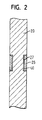
- plunger or anchor shaft 20 and target ring 26 is in the figure 2 shown in detail. It can be seen in particular that the plunger 20 and the in the circumferential groove 27 in the ram inserted target ring 26 by means of a soldering or bonding layer 40 produced by adhesive bonding.
- the connecting layer 40 is for the mechanical decoupling of the plunger 20 and of the target ring 26 is designed to be force-isolating. This means that the Connection layer 40 in particular that caused by vibrations of the plunger caused compressive and tensile stresses, which are no longer be transferred to the target ring 26.
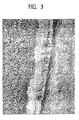
- connection layer 40 is one porous solder joint with a porosity of at least 10%, measured as Pore volume in relation to the volume of the sample.
- the solder joint can by soldering the plunger 20 and the target ring 26 with conventional, mostly silver-containing high-temperature solders are produced that additionally Contain sacrificial materials or propellants to create porosity. about the proportion of the sacrificial materials or the blowing agents can be the porosity of the connection layer can be set in a targeted manner, with the porosity should be at least 10%. Below this limit is the force isolating one Effect of the connection layer is no longer guaranteed.
- connection layer 40 is at least 30%, which makes the Elasticity of the connection layer and its vibration-damping effect can also be increased.
- connection layer made of an elastomer, i.e. a plastic Rubber elasticity. It is also conceivable for gluing the Tappet 20 and the target 26 to use a foam, for example based on polyurethane, which creates a porous, closed-cell or can form open-cell connection layer 40.
- Test trials with the assembly according to the invention in one camshaftless valve train resulted in a significant reduction in Interference signals at the sensor and thus an improved accuracy of Determining the position of the ram. Ultimately, this will result in improved control of the valve train, which also increases the life of the component.
Landscapes
- Engineering & Computer Science (AREA)
- Mechanical Engineering (AREA)
- General Engineering & Computer Science (AREA)
- Valve Device For Special Equipments (AREA)
- Valve-Gear Or Valve Arrangements (AREA)
Applications Claiming Priority (2)
| Application Number | Priority Date | Filing Date | Title |
|---|---|---|---|
| DE20209369U DE20209369U1 (de) | 2002-06-17 | 2002-06-17 | Baugruppe für einen Aktuator und die Baugruppe enthaltender nockenwellenloser Aktuator |
| DE20209369U | 2002-06-17 |
Publications (1)
| Publication Number | Publication Date |
|---|---|
| EP1375845A1 true EP1375845A1 (fr) | 2004-01-02 |
Family
ID=7972250
Family Applications (1)
| Application Number | Title | Priority Date | Filing Date |
|---|---|---|---|
| EP03011134A Withdrawn EP1375845A1 (fr) | 2002-06-17 | 2003-05-23 | Actionneur de soupapes sans arbre à cames avec détecteur de position de la tige de soupape |
Country Status (2)
| Country | Link |
|---|---|
| EP (1) | EP1375845A1 (fr) |
| DE (1) | DE20209369U1 (fr) |
Families Citing this family (3)
| Publication number | Priority date | Publication date | Assignee | Title |
|---|---|---|---|---|
| DE102004029504B4 (de) * | 2004-06-18 | 2008-05-08 | Trw Automotive Gmbh | Verfahren zur Herstellung eines Aktuators und nach dem Verfahren erhältlicher Aktuator |
| DE102006045827A1 (de) * | 2006-09-22 | 2008-04-10 | Dichtungstechnik G. Bruss Gmbh & Co. Kg | Axialverschiebbares Bauteil insbesondere in einem Kraftfahrzeugmotor oder -getriebe |
| US8985077B2 (en) | 2013-03-08 | 2015-03-24 | Ford Global Technologies, Llc | Valvetrain impact absorber |
Citations (4)
| Publication number | Priority date | Publication date | Assignee | Title |
|---|---|---|---|---|
| EP0446969A2 (fr) * | 1984-02-10 | 1991-09-18 | Kabushiki Kaisha Sg | Dispositif de détection de la position linéaire |
| US5652510A (en) * | 1994-06-03 | 1997-07-29 | Sony Corporation | Linear magnetic shaft position sensor monitoring changes in the inductance in a coil |
| EP0915319A1 (fr) * | 1997-11-06 | 1999-05-12 | Isuzu Ceramics Research Institute Co., Ltd. | Corps en mouvement et moyen pour détecter sa position |
| DE20115060U1 (de) * | 2001-09-12 | 2002-01-31 | TRW Deutschland GmbH, 30890 Barsinghausen | Nockenwellenloser Aktuator für Betätigung eines Hubventils |
-
2002
- 2002-06-17 DE DE20209369U patent/DE20209369U1/de not_active Expired - Lifetime
-
2003
- 2003-05-23 EP EP03011134A patent/EP1375845A1/fr not_active Withdrawn
Patent Citations (4)
| Publication number | Priority date | Publication date | Assignee | Title |
|---|---|---|---|---|
| EP0446969A2 (fr) * | 1984-02-10 | 1991-09-18 | Kabushiki Kaisha Sg | Dispositif de détection de la position linéaire |
| US5652510A (en) * | 1994-06-03 | 1997-07-29 | Sony Corporation | Linear magnetic shaft position sensor monitoring changes in the inductance in a coil |
| EP0915319A1 (fr) * | 1997-11-06 | 1999-05-12 | Isuzu Ceramics Research Institute Co., Ltd. | Corps en mouvement et moyen pour détecter sa position |
| DE20115060U1 (de) * | 2001-09-12 | 2002-01-31 | TRW Deutschland GmbH, 30890 Barsinghausen | Nockenwellenloser Aktuator für Betätigung eines Hubventils |
Also Published As
| Publication number | Publication date |
|---|---|
| DE20209369U1 (de) | 2002-10-31 |
Similar Documents
| Publication | Publication Date | Title |
|---|---|---|
| EP2050107B1 (fr) | Dispositif de réglage électromagnétique | |
| EP2932515B1 (fr) | Actionneur électromagnétique | |
| EP2685145A2 (fr) | Soupape | |
| DE102008008761A1 (de) | Betätigungsmagnet | |
| EP2097913B1 (fr) | Procédé pour la fabrication d'un composant de circuit magnétique fixe | |
| DE102016224288A1 (de) | Elektromagnetisches Stellglied, Flussscheibenkörper für ein elektromagnetisches Stellglied und Verfahren zur Herstellung eines elektromagnetischen Stellgliedes | |
| EP2405167A2 (fr) | Soupape électromagnétique pour un moteur à combustion interne | |
| EP1430202B1 (fr) | Actionneur destine a actionner une soupape de levage | |
| DE20209369U1 (de) | Baugruppe für einen Aktuator und die Baugruppe enthaltender nockenwellenloser Aktuator | |
| DE102012224240A1 (de) | Magnetventil und Verfahren zum Herstellen eines Magnetventils | |
| DE102020124188B4 (de) | Parksperre zum Feststellen eines Getriebes, insbesondere eines Kraftfahrzeuggetriebes, sowie Getriebe | |
| DE102017106476A1 (de) | Magnetaktor mit Buchse als Ankergleitlager | |
| DE102014215589A1 (de) | Restluftspaltscheibe für eine Magnetbaugruppe eines Magnetventils und Verfahren zum Herstellen einer Restluftspaltscheibe | |
| DE102007043553A1 (de) | Elektromagnetventil | |
| DE102013226860A1 (de) | Hubmagnetanordnung und Verfahren zur Herstellung einer Hubmagnetanordnung | |
| EP1567825A1 (fr) | Dispositif de mesure de la course de soupapes | |
| DE102022206134A1 (de) | Verfahren zum Herstellen eines Positionsgebers für eine Nockenwelle | |
| WO2003072954A1 (fr) | Procede de production d'un tube sous pression d'un electro-aimant de levage et tube sous pression d'un electro-aimant de levage | |
| DE102008061396A1 (de) | Betätigungselement einer elektromagnetischen Stelleinheit eines Hydraulikventils | |
| EP1437485B1 (fr) | Méthode pour produire un actionneur ayant des moyens de mesure de positionnement comprennant de la poudre métallurgique , et actionner | |
| DE102010062077A1 (de) | Ventileinrichtung mit einem wenigstens abschnittsweise zylindrischen Bewegungselement | |
| DE102015001391B4 (de) | Elektromagnet und Herstellverfahren zur Herstellung eines Elektromagneten | |
| DE102008002487A1 (de) | Verfahren zur Hubeinstellung eines Ventils | |
| DE19929158B4 (de) | Elektromagnetventil | |
| WO2022117818A1 (fr) | Dispositif actionneur électromagnétique, électrovalve et procédé de fonctionnement du dispositif actionneur électromagnétique |
Legal Events
| Date | Code | Title | Description |
|---|---|---|---|
| PUAI | Public reference made under article 153(3) epc to a published international application that has entered the european phase |
Free format text: ORIGINAL CODE: 0009012 |
|
| AK | Designated contracting states |
Kind code of ref document: A1 Designated state(s): AT BE BG CH CY CZ DE DK EE ES FI FR GB GR HU IE IT LI LU MC NL PT RO SE SI SK TR |
|
| AX | Request for extension of the european patent |
Extension state: AL LT LV MK |
|
| AKX | Designation fees paid | ||
| REG | Reference to a national code |
Ref country code: DE Ref legal event code: 8566 |
|
| STAA | Information on the status of an ep patent application or granted ep patent |
Free format text: STATUS: THE APPLICATION IS DEEMED TO BE WITHDRAWN |
|
| 18D | Application deemed to be withdrawn |
Effective date: 20040703 |