EP1375986A2 - Soupape à siège de modulation précise - Google Patents
Soupape à siège de modulation précise Download PDFInfo
- Publication number
- EP1375986A2 EP1375986A2 EP03253838A EP03253838A EP1375986A2 EP 1375986 A2 EP1375986 A2 EP 1375986A2 EP 03253838 A EP03253838 A EP 03253838A EP 03253838 A EP03253838 A EP 03253838A EP 1375986 A2 EP1375986 A2 EP 1375986A2
- Authority
- EP
- European Patent Office
- Prior art keywords
- valve
- flow
- valve plug
- plug
- sealing member
- Prior art date
- Legal status (The legal status is an assumption and is not a legal conclusion. Google has not performed a legal analysis and makes no representation as to the accuracy of the status listed.)
- Withdrawn
Links
Images


Classifications
-
- F—MECHANICAL ENGINEERING; LIGHTING; HEATING; WEAPONS; BLASTING
- F16—ENGINEERING ELEMENTS AND UNITS; GENERAL MEASURES FOR PRODUCING AND MAINTAINING EFFECTIVE FUNCTIONING OF MACHINES OR INSTALLATIONS; THERMAL INSULATION IN GENERAL
- F16K—VALVES; TAPS; COCKS; ACTUATING-FLOATS; DEVICES FOR VENTING OR AERATING
- F16K25/00—Details relating to contact between valve members and seats
-
- F—MECHANICAL ENGINEERING; LIGHTING; HEATING; WEAPONS; BLASTING
- F16—ENGINEERING ELEMENTS AND UNITS; GENERAL MEASURES FOR PRODUCING AND MAINTAINING EFFECTIVE FUNCTIONING OF MACHINES OR INSTALLATIONS; THERMAL INSULATION IN GENERAL
- F16K—VALVES; TAPS; COCKS; ACTUATING-FLOATS; DEVICES FOR VENTING OR AERATING
- F16K1/00—Lift valves or globe valves, i.e. cut-off apparatus with closure members having at least a component of their opening and closing motion perpendicular to the closing faces
- F16K1/32—Details
- F16K1/54—Arrangements for modifying the way in which the rate of flow varies during the actuation of the valve
-
- Y—GENERAL TAGGING OF NEW TECHNOLOGICAL DEVELOPMENTS; GENERAL TAGGING OF CROSS-SECTIONAL TECHNOLOGIES SPANNING OVER SEVERAL SECTIONS OF THE IPC; TECHNICAL SUBJECTS COVERED BY FORMER USPC CROSS-REFERENCE ART COLLECTIONS [XRACs] AND DIGESTS
- Y10—TECHNICAL SUBJECTS COVERED BY FORMER USPC
- Y10T—TECHNICAL SUBJECTS COVERED BY FORMER US CLASSIFICATION
- Y10T137/00—Fluid handling
- Y10T137/8593—Systems
- Y10T137/86493—Multi-way valve unit
- Y10T137/86718—Dividing into parallel flow paths with recombining
- Y10T137/86734—With metering feature
Definitions
- the present invention relates to a globe valve for the volumetric control of fluid flow through a conduit. More specifically, the present invention relates to a globe valve having a unique valve plug that provides essentially bumpless modulation of fluid flow from the initiation of flow through a maximum stroke.
- Globe valves typically include a valve plug that is movable toward and away from a valve seat formed in a valve port between a fluid inlet and a fluid outlet.
- the movement of the valve plug is typically controlled by an actuator, such as a manual handle or some other type of remotely controlled actuation system.
- the flow of fluid through the valve is modulated by varying the clearance between the outside diameter of the valve plug and the inside diameter of the valve port.
- the clearance area between the outside diameter of the valve plug and the inside diameter of the valve port ranges from a minimum to a maximum value.
- valve's rangeability The ratio of the full rated flow of a valve to the initial controllable flow is referred to as the valve's "rangeability".
- rangeability The higher the rangeability value, the better the control system can operate to provide the desired fluid flow.
- valves in a family designed for low flow rates have the lowest rangeability. When utilizing such a valve, the control system has difficulty in achieving accuracy and stability requirements over the required flow rates, especially at low flow rates.
- the present invention relates to a precision modulating globe valve that creates essentially bumpless modulation of fluid flow from the initiation of flow through a maximum stroke.
- the globe valve of the present invention thereby increases the "rangeability" of the valve by providing more accurate control at low flow rates.
- the precision modulating globe valve of the present invention includes a valve plug that is movable along the longitudinal flow axis of a valve port positioned between an inlet passageway and an outlet passageway. Movement of the valve plug within the valve port controls the flow of fluid through the valve port from the inlet of the globe valve to the outlet of the globe valve.
- the valve port of the globe valve includes a sealing member, such as an elastomeric O-ring, positioned along the inner wall of the valve port.
- the sealing member protrudes from the inner wall of the valve port and engages the outer surface of the valve plug when the valve plug is positioned within the valve port.
- the sealing member provides a fluid-tight seal between the outer surface of the valve plug and the valve port to prevent the flow of fluid along the outer surface of the valve plug.
- the valve plug generally includes a cylindrical outer surface sized to be received within the valve port.
- the valve plug includes at least one flow modulating channel recessed from the outer surface of the valve plug. The flow modulating channel provides a flow path for fluid to pass between the sealing member in the valve port and the valve plug.
- the flow modulating channel extends from a minimum flow end to a maximum flow end.
- the flow modulating channel is constructed such that the cross-sectional area of the flow modulating channel recessed from the otherwise cylindrical outer surface of the valve plug increases from the minimum flow end of the channel to the maximum flow end of the channel. In this manner, as the valve plug is moved relative to the stationary sealing member positioned in the valve port from a closed position to a fully open position, fluid flow from the inlet passageway to the outlet passageway increases.
- the flow modulating channel includes a flat face surface recessed from the outer surface of the valve plug.
- the flat face surface is angled inward such that the flow modulating channel increases in both depth and width from the minimum flow end to the maximum flow end.
- the flow modulating channel can increase in only width or in only depth relative to the outer surface of the valve plug from the minimum flow end to the maximum flow end.
- the recessed radial cross-sectional area of the flow modulating channel increases from the minimum flow end to the maximum flow end of the channel.
- the valve plug further includes a sealing ring that contacts a seat formed on the valve port to further aid in preventing fluid flow when the valve plug is in the fully closed position.
- the sealing ring formed on the valve plug is not required, but further aids in preventing fluid flow when the valve plug is in the completely closed position.
- a modulating plug-type control valve, or globe valve, 10 of the present invention is generally illustrated in Fig. 1.
- the globe valve 10 includes a valve body 12 that defines an inlet opening 14 for receiving a flow of fluid.
- the inlet opening 14 delivers a flow of fluid to an inlet passageway 16 that is in fluid communication with a valve port 18.
- the valve port 18 extends along a longitudinal flow axis and provides fluid communication between the inlet passageway 16 and an outlet passageway 20.
- the outlet passageway 20 allows fluid to flow out of an outlet opening 22.
- the globe valve 10 could also be a three-way mixing valve.
- the globe valve 10 includes a valving assembly 24 that controls the flow of fluid through the valve port 18 from the inlet passageway 16 to the outlet passageway 20.
- the valving assembly 24 includes a valve plug 26 coupled to a valve stem 28 such that the valve plug 26 is movable along the longitudinal axis of the valve port 18 between a fully open position (Fig. 14b) and a fully closed position (Fig. 1), as will be described in greater detail below.
- valve body 12 and the globe valve 10 of the present invention are particularly suitable for controlling the flow of a fluid, such as steam, water or air, in a hydronic HVAC system (not shown), although other uses are contemplated as being within the scope of the present invention.
- a fluid such as steam, water or air
- the valve port 18 includes a valve seat 30 that varies in diameter radially inward from an outer edge 32 to an inner edge 34.
- the valve seat 30 defines the surface that receives a portion of the valve plug, as will be described in greater detail below.
- the valve port 18 further includes a channel 36 that is recessed from the otherwise cylindrical inner wall 38.
- the channel 36 extends around the entire cylindrical inner wall 38 and is sized to receive a sealing member 40.
- the sealing member 40 is an elastomeric O-ring having a thickness slightly larger than the width of the channel 36. As can be seen in Fig. 3, the sealing member 40 protrudes radially inward from the cylindrical inner wall 38 such that when the valve plug moves through the valve port 18, the sealing member 40 contacts the outer surface of the valve plug and is compressed between the valve plug and the valve port 18 to provide a seal therebetween.
- the valving assembly 24 includes a valve plug 26 secured to a valve stem 28. As shown in Fig. 1, the valve plug 26 is positioned within the valve port 18 to control the flow of fluid through the valve port 18.
- the valve plug 26 is a generally cylindrical member having a main body 42 extending along a longitudinal axis between a first end 44 and a second end 46. Specifically, the main body 42 is defined by a cylindrical outer surface 48 having constant diameter from the first end 44 to the second end 46. The second end of the valve body 26 includes a tapered edge surface 50.
- the first end 44 of the valve body is positioned adjacent to a recessed channel 52.
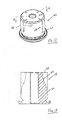
- the recessed channel 52 as can be clearly seen in Fig. 7, is sized to receive a sealing ring 54, as shown installed in Fig. 4.
- the recessed channel 52 is positioned between the first end 44 and an expanded diameter end cap 56.
- the end cap 56 has a diameter slightly larger than the diameter of the valve port 18 to prevent the passage of the valve plug through the valve port 18.
- the entire valve plug 26 is formed from metal, although other materials are contemplated.
- the sealing member 40 when positioned in the channel 36 of the valve port 18, contacts the outer surface 48 of the valve plug 26 to prevent the flow of fluid past the valve plug 26.
- the flexible properties of the sealing member 40 compensates for tolerance variations between the valve port 18 and the outer surface of the valve plug 26.
- the valve plug 26 includes at least one flow modulating channel 58 formed along the outer surface 48 of the valve plug 26.
- the flow modulating channel 58 is radially recessed from the otherwise cylindrical outer surface 48 such that the flow modulating channel 58 allows fluid to pass between the sealing member 40 and the outer surface 48 of the valve plug when the valve plug 26 moves from the fully closed position (Fig. 1) to a partially open position, as illustrated in Fig. 14a.
- the only flow from the inlet passageway 16 to the outlet passageway 20 through the valve port 18 is through the flow modulating channel 58.
- the flow modulating channel 58 provides for a controlled and accurate flow rate as compared to a typical globe valve in which the flow of fluid is controlled by the diametrical flow around the outer surface of the valve plug.
- the flow modulating channel 58 extends from a minimum flow end 60 to a maximum flow end 62.
- the distance A between the minimum flow end 60 of the channel 58 and the first end 44 of the main body 42 defines a sealing area 65.
- the width A of the sealing area 65 is selected such that the sealing member 40 can engage the entire outer surface 48 of the valve plug 26 in the completely closed position. When the valve plug 26 is in the completely closed position, as shown in Fig. 1, the sealing member 40 prevents the flow of fluid along the outer surface 48 of the valve plug 26.
- the flow modulating channel 58 includes a flat face surface 64 that increases in width from the minimum flow end 60 to the maximum flow end 62. As illustrated, the maximum flow end 62 has a width B. In the embodiment of the invention illustrated, the width of the channel B is 0.252" while the diameter of the valve plug is 0.70"
- the back face surface 64 is angled radially inward relative to the outer surface 48 at an angle ⁇ .
- the angle ⁇ is 3°, although other angles are contemplated depending on the range of flow rates required.
- both the width B and the depth of the flow modulating channel 58 increase from the minimum flow end 60 to the maximum flow end 62.
- the flow modulating channel 58 shown in Figs. 5 and 6 increases in both width and depth, it is significant that the radial cross-sectional area of the flow modulating channel that is recessed from the outer surface 48 increase from the minimum flow end 60 to the maximum flow end 62.
- the increase in the radially cross-sectional area of the flow modulating channel 58 can be created by increasing the width of the flow modulating channel, increasing the depth of the flow modulating channel, or a combination of the two.
- the radial cross-sectional area of the flow modulating channel 52 that is recessed from the outer surface 48 controls the amount of fluid that can flow past the sealing member 40 in the valve port.
- valve plug 26 moves downwardly along the longitudinal axis of the valve port 18 relative to the stationary sealing member 40.
- the minimum flow end 60 of the flow modulating channel 58 passes beneath the sealing member 40.
- the flow modulating channel 38 creates an increasing gap between the sealing member 40 and the outer surface 48 of the valve plug 26.
- the increasing open area between the flow modulating channel 58 and the sealing member 40 from the minimum flow end 60 to the maximum flow end 62 allows the flow rate of fluid to increase as the valve plug 26 moves from the closed position to the fully open position.
- the sealing ring 54 positioned in the valve plug 26 contacts the valve seat 30 to further prevent the flow of fluid past the valve plug 26.
- the sealing ring 54 is not required in accordance with the present invention, since the sealing member 40 provides the required seal around the outer surface of the valve plug 26 to prevent the flow of fluid when the valve plug 26 is in its closed position.
- valve plugs 26 used to provide different flow rates between the inlet flow passageway and the outlet flow passageway.
- a single flow modulating channel 58 is formed along the outer surface 48.
- a globe valve utilizing this valve plug may be capable of flow rate near 0.10 C v .
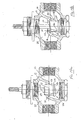
- Fig. 9 illustrates a valve plug 26a having a pair of flow modulating channels 58 positioned 180° from each other along the outer surface 48.
- the valve plug 26 illustrated in Fig. 9 is capable of flow rates near 0.20 C v , double the flow rate possible with the valve plug 26 of Fig. 8.
- Fig. 10 illustrates a valve plug 26c having four flow modulating channels 58, each positioned 90° from each other.
- the valve plug 26c illustrated in Fig. 10 allows for flow rates near 0.40 C v , four times the flow rate of the design illustrated in Fig. 8.
- Fig. 11 illustrates a valve plug 26d having eight flow modulating channels 58.
- the flow modulating channels 58 shown in Fig. 11 allow the valve plug 26d to create a rating of 0.80 C v , which is eight times the flow rate of the valve plug 26 shown in Fig. 8.
- increasing the number of flow modulating channels 58 along the outer surface 48 of the valve plug 26 increases the flow rating of the valve plug 26.
- the number of flow modulating channels 58 is dictated by the size of the flow modulating channels and the diameter of the valve plug, as can be understood.
- the valve plug 66 shown in Fig. 12 includes at least four flow modulating channels 58 formed in the otherwise cylindrical outer surface 48.
- the flow modulating channels 58 are each a slot having a constant width extending from the minimum flow end 60 to the maximum flow end 62.
- the recessed radial cross-sectional area of the flow modulating channel 58 increases from the minimum flow end 60 to the maximum flow end 62.
- the depth of the flow modulating channels 58 is defined by a recessed back surface 63 and increases from the minimum flow end 60 to the maximum flow end 62.
- the depth of the flow modulating channel 58 increases from the minimum flow end 60 to the maximum flow end 62.
- the flow modulating channel 58 is machined into the outer surface 48.
- the increasing depth of the flow modulating channel 58 provides similar flow rates to the embodiment of Fig. 5, since the recessed area of the flow modulating channel 58 increases at nearly the same rate as the increase in the recessed area of the embodiment illustrated in Fig. 5.
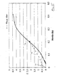
- Fig. 15 illustrates the flow characteristics of a prior art flow valve and the precision modulating globe valve of the present invention.
- the prior art globe valve represented by the broken line 70
- the valve is typically rated for flow rates illustrated by point 72.
- the rangeability of the prior art valve was determined by the minimum flow characteristic of approximately 0.5 C v to a maximum flow of 4.4 C v .
- the solid line 76 illustrates the flow characteristics of the precision modulating globe valve of the present invention. As illustrated in Fig. 15, the flow characteristics extend well below 0.5 C v such that the rangeability of the valve has been effectively increased. The increased rangeability provides for more precision flow modulation at lower C v rates.
Landscapes
- Engineering & Computer Science (AREA)
- General Engineering & Computer Science (AREA)
- Mechanical Engineering (AREA)
- Lift Valve (AREA)
- Taps Or Cocks (AREA)
Applications Claiming Priority (2)
| Application Number | Priority Date | Filing Date | Title |
|---|---|---|---|
| US10/184,245 US6926249B2 (en) | 2002-06-28 | 2002-06-28 | Precision modulating globe valve |
| US184245 | 2002-06-28 |
Publications (2)
| Publication Number | Publication Date |
|---|---|
| EP1375986A2 true EP1375986A2 (fr) | 2004-01-02 |
| EP1375986A3 EP1375986A3 (fr) | 2004-01-14 |
Family
ID=29717953
Family Applications (1)
| Application Number | Title | Priority Date | Filing Date |
|---|---|---|---|
| EP20030253838 Withdrawn EP1375986A3 (fr) | 2002-06-28 | 2003-06-18 | Soupape à siège de modulation précise |
Country Status (8)
| Country | Link |
|---|---|
| US (1) | US6926249B2 (fr) |
| EP (1) | EP1375986A3 (fr) |
| KR (1) | KR20040002758A (fr) |
| CN (2) | CN100385156C (fr) |
| AU (1) | AU2003204640B2 (fr) |
| BR (1) | BR0301729A (fr) |
| CA (1) | CA2432087A1 (fr) |
| MX (1) | MXPA03005831A (fr) |
Cited By (2)
| Publication number | Priority date | Publication date | Assignee | Title |
|---|---|---|---|---|
| EP2019239A1 (fr) * | 2007-07-02 | 2009-01-28 | Crane Limited | Raccordement pour vanne de contrôle de fluide |
| EP3338975A3 (fr) * | 2016-12-20 | 2018-07-11 | BIESSE S.p.A. | Machine de placage de panneaux en bois ou matériau similaire |
Families Citing this family (10)
| Publication number | Priority date | Publication date | Assignee | Title |
|---|---|---|---|---|
| US7469708B2 (en) * | 2004-12-21 | 2008-12-30 | Fisher Controls International Llc | Universal fluid valve body |
| US7708254B2 (en) | 2007-08-07 | 2010-05-04 | Warren Controls, Inc. | Actuator apparatus for operating and locking a control valve and a method for its use |
| DE112009002230B4 (de) * | 2008-10-01 | 2023-12-07 | Borgwarner Inc. | Wastegate für ein turbogeladenes verbrennungsmotorsystem und wastegate-abgassteuerungssystem |
| DE202008013969U1 (de) * | 2008-10-20 | 2009-01-08 | Bürkert Werke GmbH & Co. KG | Ventil mit variablem Durchfluss |
| ITCR20130016A1 (it) * | 2013-05-24 | 2014-11-25 | Wonder Spa | Valvola di aspirazione per sospensione pneumatica di cabine di autocarri |
| WO2019018560A1 (fr) * | 2017-07-19 | 2019-01-24 | Imi Hydronic Engineering, Inc. | Régulateur de débit à compensation de pression à seulement deux pressions |
| CN107907647B (zh) * | 2017-12-15 | 2023-08-25 | 重庆晓渝机器人有限公司 | 控制生物传感器储液腔通断状态的截断装置 |
| US20190226592A1 (en) * | 2018-01-25 | 2019-07-25 | Honeywell International Inc. | Double block and bleed valve with flex bypass for effective and efficient system isolation |
| US11598435B2 (en) * | 2019-05-08 | 2023-03-07 | Parker-Hannifin Corporation | Stop/check/expansion plug valve |
| US12222039B2 (en) | 2021-03-22 | 2025-02-11 | Ichor Systems, Inc. | Guided flow valve assembly and system incorporating same |
Family Cites Families (12)
| Publication number | Priority date | Publication date | Assignee | Title |
|---|---|---|---|---|
| US2014314A (en) * | 1931-07-22 | 1935-09-10 | Phillips Petroleum Co | Adjustable orifice valve |
| US2541176A (en) | 1945-01-22 | 1951-02-13 | Mason Neilan Regulator Company | Control valve |
| US3606911A (en) | 1969-11-14 | 1971-09-21 | Masoneilan Int Inc | Invertible valve trim for control valves |
| FR2082646A5 (fr) | 1970-03-23 | 1971-12-10 | Monrocq Raymond | |
| JPS5337574B2 (fr) * | 1972-02-18 | 1978-10-09 | ||
| US4795131A (en) * | 1986-10-24 | 1989-01-03 | Albany International Corp. | Vacuum controller |
| US5393035A (en) * | 1994-02-23 | 1995-02-28 | Dynamic Air, Inc. | Flow control valve |
| US5516079A (en) * | 1995-01-27 | 1996-05-14 | Baumann Hans D | Small flow control valve with tight shutoff capability |
| SE508979C2 (sv) * | 1996-07-11 | 1998-11-23 | Tac Ab | Ventilkägla, ventil och sätt att framställa en ventilkägla |
| US5937890A (en) | 1998-01-09 | 1999-08-17 | Griswold Controls, Inc. | Insert for flow throttling ball valves |
| US6276397B1 (en) | 2000-06-12 | 2001-08-21 | Flow Design, Inc. | Apparatus and method for shaping fluid flow |
| US20020017327A1 (en) * | 2000-07-28 | 2002-02-14 | Shigehiro Kawaai | Single seat valve apparatus |
-
2002
- 2002-06-28 US US10/184,245 patent/US6926249B2/en not_active Expired - Lifetime
-
2003
- 2003-06-11 AU AU2003204640A patent/AU2003204640B2/en not_active Ceased
- 2003-06-12 CA CA 2432087 patent/CA2432087A1/fr not_active Abandoned
- 2003-06-18 EP EP20030253838 patent/EP1375986A3/fr not_active Withdrawn
- 2003-06-20 BR BR0301729A patent/BR0301729A/pt not_active IP Right Cessation
- 2003-06-26 MX MXPA03005831A patent/MXPA03005831A/es active IP Right Grant
- 2003-06-27 CN CNB031480411A patent/CN100385156C/zh not_active Expired - Lifetime
- 2003-06-27 KR KR1020030042317A patent/KR20040002758A/ko not_active Ceased
- 2003-06-27 CN CN200810096203XA patent/CN101270816B/zh not_active Expired - Lifetime
Cited By (2)
| Publication number | Priority date | Publication date | Assignee | Title |
|---|---|---|---|---|
| EP2019239A1 (fr) * | 2007-07-02 | 2009-01-28 | Crane Limited | Raccordement pour vanne de contrôle de fluide |
| EP3338975A3 (fr) * | 2016-12-20 | 2018-07-11 | BIESSE S.p.A. | Machine de placage de panneaux en bois ou matériau similaire |
Also Published As
| Publication number | Publication date |
|---|---|
| US20040000654A1 (en) | 2004-01-01 |
| MXPA03005831A (es) | 2005-02-14 |
| CN100385156C (zh) | 2008-04-30 |
| CN101270816B (zh) | 2011-01-12 |
| CA2432087A1 (fr) | 2003-12-28 |
| AU2003204640B2 (en) | 2007-09-20 |
| KR20040002758A (ko) | 2004-01-07 |
| CN101270816A (zh) | 2008-09-24 |
| CN1472453A (zh) | 2004-02-04 |
| US6926249B2 (en) | 2005-08-09 |
| EP1375986A3 (fr) | 2004-01-14 |
| BR0301729A (pt) | 2004-08-17 |
| AU2003204640A1 (en) | 2004-01-15 |
Similar Documents
| Publication | Publication Date | Title |
|---|---|---|
| US11592115B2 (en) | Fluid valve | |
| US6926249B2 (en) | Precision modulating globe valve | |
| US7225830B1 (en) | Fluid control valve | |
| US6520481B2 (en) | Linearly regulated gas valve for gas burners | |
| US4537384A (en) | In-line check valve having combined downstream poppet support and flow control elements | |
| US3443793A (en) | Variable area orifice,rotary control valve | |
| EP3368802B1 (fr) | Soupape comportant un insert de vanne | |
| US20140209828A1 (en) | Flow characterizing device and ball valve with such a flow characterizing device | |
| US6935616B2 (en) | Balanced plug valve | |
| EP2921750A1 (fr) | Soupape | |
| EP0085565A1 (fr) | Robinet d'arrêt | |
| EP3540278A1 (fr) | Joint d'étanchéité pour soupape à bille et ensemble d'obturateur à bille comprenant le joint d'étanchéité | |
| US4503884A (en) | Angle globe valve | |
| EP2565502B1 (fr) | Robinet pour conduites d'acheminement d'eau | |
| US11143312B2 (en) | Eccentric rotary valve | |
| US4056124A (en) | Fluid mixing valve for supplying controllable proportions of two inlet fluids from a single outlet | |
| US11441689B2 (en) | Ceramic disc valve cartridge | |
| CA2932538A1 (fr) | Ensemble clapet a billes | |
| US20060042702A1 (en) | Fluted reciprocating ball valve | |
| EP0078912B1 (fr) | Cartouche à pression interne zéro | |
| EP4155588A1 (fr) | Ensemble soupape | |
| EP2333460B1 (fr) | Soupape champignon dotée d'un gain de surface à double flux | |
| US12510197B2 (en) | Valve device with ball locks | |
| US20240302851A1 (en) | Pressure limiter | |
| US20190316699A1 (en) | Low-torque valve |
Legal Events
| Date | Code | Title | Description |
|---|---|---|---|
| PUAI | Public reference made under article 153(3) epc to a published international application that has entered the european phase |
Free format text: ORIGINAL CODE: 0009012 |
|
| PUAL | Search report despatched |
Free format text: ORIGINAL CODE: 0009013 |
|
| AK | Designated contracting states |
Kind code of ref document: A2 Designated state(s): AT BE BG CH CY CZ DE DK EE ES FI FR GB GR HU IE IT LI LU MC NL PT RO SE SI SK TR |
|
| AX | Request for extension of the european patent |
Extension state: AL LT LV MK |
|
| AK | Designated contracting states |
Kind code of ref document: A3 Designated state(s): AT BE BG CH CY CZ DE DK EE ES FI FR GB GR HU IE IT LI LU MC NL PT RO SE SI SK TR |
|
| AX | Request for extension of the european patent |
Extension state: AL LT LV MK |
|
| AKX | Designation fees paid | ||
| REG | Reference to a national code |
Ref country code: DE Ref legal event code: 8566 |
|
| STAA | Information on the status of an ep patent application or granted ep patent |
Free format text: STATUS: THE APPLICATION IS DEEMED TO BE WITHDRAWN |
|
| 18D | Application deemed to be withdrawn |
Effective date: 20040715 |