EP1376009A2 - Brûleur à charbon pulverisé - Google Patents
Brûleur à charbon pulverisé Download PDFInfo
- Publication number
- EP1376009A2 EP1376009A2 EP03017217A EP03017217A EP1376009A2 EP 1376009 A2 EP1376009 A2 EP 1376009A2 EP 03017217 A EP03017217 A EP 03017217A EP 03017217 A EP03017217 A EP 03017217A EP 1376009 A2 EP1376009 A2 EP 1376009A2
- Authority
- EP
- European Patent Office
- Prior art keywords
- secondary air
- nozzle
- pulverized coal
- burner
- air
- Prior art date
- Legal status (The legal status is an assumption and is not a legal conclusion. Google has not performed a legal analysis and makes no representation as to the accuracy of the status listed.)
- Withdrawn
Links
Images
Classifications
-
- F—MECHANICAL ENGINEERING; LIGHTING; HEATING; WEAPONS; BLASTING
- F23—COMBUSTION APPARATUS; COMBUSTION PROCESSES
- F23D—BURNERS
- F23D1/00—Burners for combustion of pulverulent fuel
-
- F—MECHANICAL ENGINEERING; LIGHTING; HEATING; WEAPONS; BLASTING
- F23—COMBUSTION APPARATUS; COMBUSTION PROCESSES
- F23C—METHODS OR APPARATUS FOR COMBUSTION USING FLUID FUEL OR SOLID FUEL SUSPENDED IN A CARRIER GAS OR AIR
- F23C2202/00—Fluegas recirculation
- F23C2202/40—Inducing local whirls around flame
-
- F—MECHANICAL ENGINEERING; LIGHTING; HEATING; WEAPONS; BLASTING
- F23—COMBUSTION APPARATUS; COMBUSTION PROCESSES
- F23C—METHODS OR APPARATUS FOR COMBUSTION USING FLUID FUEL OR SOLID FUEL SUSPENDED IN A CARRIER GAS OR AIR
- F23C2900/00—Special features of, or arrangements for combustion apparatus using fluid fuels or solid fuels suspended in air; Combustion processes therefor
- F23C2900/09002—Specific devices inducing or forcing flue gas recirculation
Definitions
- the present invention relates to a pulverized coal burner which is a type of pulverized coal float-firing burner and, more particularly, to a pulverized coal burner suitable for lowering the concentration of nitrogen oxides (hereunder, referred to as NOx).
- NOx nitrogen oxides
- coal includes a larger amount of nitrogen, compared with gaseous fuel and liquid fuel. Therefore, it is more important to decrease NOx produced by combustion of pulverized coals than in a case of combustion of gaseous fuel or liquid fuel.
- NOx produced by combustion of pulverized coals is almost all NOx that is produced by oxidizing nitrogen contained in coal, that is, so-called fuel NOx.
- fuel NOx In order to decrease the fuel NOx, various burner structures and burning methods have been studied.
- JP A 1-305206 (US patent 4,930,430), JP A 3-211304, JP A 3-110308, US patent 5,231,937, US patent 5,680,823, etc. disclose a method of producing flame of low oxygen concentration atmosphere and completely burning coal, and a structure having a fuel nozzle for pneumatically transferring coal at the center thereof and an air injecting nozzle arranged outside the fuel nozzle.
- JP A 1-305206 discloses a method of stabilization of flame by providing, at an outlet end portion of a nozzle, an obstacle against the flow direction of gas.
- JP A 3-311304, JP A 3-110308 and US patent 5, 231, 937 disclose stabilization of flame by providing a flame stabilizing ring at the tip of a pulverized coal nozzle.
- recirculating zones are formed downstream of the tip of the pulverized coal nozzle by providing the flame stabilizing ring or obstacle at the tip of the pulverized coal nozzle. Since a high temperature gas stays in the recirculating zones, ignition of pulverized coals progresses and the stability of flame can be raised.
- An object of the invention is to provide a pulverized coal burner which can further decrease NOx formation by solving the above-mentioned problems of the prior arts.
- the present invention is characterized in that, in a pulverized coal burner comprising a pulverized coal nozzle for jetting or spouting a mixture of pulverized coals and primary air, a secondary air nozzle concentrically arranged around the outer periphery of the pulverized coal nozzle, a tertiary air nozzle concentrically arranged around the outer periphery of the secondary air nozzle and an expanded portion formed at the end of an outer peripheral wall of the secondary air nozzle, a flow shift means is provided for shifting secondary air jetted from the secondary air nozzle toward the radially outer side so that the secondary air flows along the expanded portion.
- the pulverized coal burner in which the secondary air nozzle and tertiary air nozzle are concentrically arranged around the outer periphery of the pulverized coal nozzle aims to suppress NOx formation by forming a NOx reducing zone of a low oxygen concentration by primary air and carry out complete combustion by forming an oxidizing flame region by mixing the secondary air and tertiary air with the flow at a downstream side of the NOx reducing region.
- pulverized coal itself is not good in ignitability, and under the condition that oxygen is short, the pulverized coal is uneasy to be ignited but flame is easily extinguished.
- the size of recirculating zone formed at a downstream side of the partition wall separating the pulverized coal nozzle and the secondary air nozzle becomes large, whereby pullback of the secondary air becomes slow. Further, by a large-sized recirculating zone, the ignitability of pulverized coals becomes good and flame becomes uneasy to be extinguished.
- a guide plate at the tip of the inner peripheral wall of the secondary air nozzle.
- An angle of the guide plate should be sharper than that of the expanded portion provided on the outer peripheral wall of the secondary air nozzle.
- a gas jet nozzle for jetting a gas toward the secondary air flowing in the vicinity of the outlet of the secondary air nozzle and shifting the secondary air to the radially outer side can be used other than the guide plate.
- an induction member for inducing or guiding the flow of secondary air flow toward the outside can be used therefor.
- the angle of the above-mentioned guide plate is in a range of 60 to 90° against the central axis of the pulverized coal nozzle, and a range of 80 to 90° is more desirable.
- a recirculating zone also is formed at a downstream side of the guide plate and pullback of secondary air and tertiary air can be made slower.
- the tip of the guide plate is preferable to be positioned downstream of the tip of the expanded portion provided on the outer peripheral wall of the secondary air nozzle.
- the tip of the guide plate also is desirable to be positioned at an upstream side of the tip of the outer peripheral wall of the tertiary air nozzle.
- the outer peripheral wall usually, is jointly served as a furnace wall of a boiler in many cases. Combustion and slug are adhered to the furnace wall, and the substances and slug, in a case of large amount, may reaches to from several kg to several hundred kg.
- the tip of the guide plate is preferable not to project into the inside of the furnace from the furnace wall jointly served as the outer peripheral wall of the tertiary air nozzle.
- the tertiary air nozzle it is preferable that outward force has been already applied when the tertiary air is jetted from the tertiary air nozzle, therefore, it is preferable to provide a swirler inside the tertiary air nozzle. Further, it is preferable to have outwardly expand ed the end portion of the outer peripheral wall of the tertiary air nozzle. Still further, it is preferable to have outwardly expanded the end portion of the inner peripheral wall of the tertiary air nozzle.
- the conventional burner in which an expanded portion is provided at the tip of the outer peripheral wall of a secondary air nozzle has been known, in the conventional burner, such a device that shifts secondary air to the radially outer side was not taken, therefore, most of the secondary air was easy to flow in the axial direction of the burner according to the inertia of the air.
- the conventional burner has such a defect that a recirculating zone between the pulverized coal nozzle and the secondary air nozzle becomes small, further, a recirculating zone comes to be easily formed between the secondary air nozzle and the tertiary air nozzle, and the secondary air and tertiary air are easy to mix with reducing flame in an earlier stage.
- a flow path narrowing member or obstacle for narrowing the flow path of the secondary air nozzle to make the flow velocity faster. It is possible to direct the flow of tertiary air to a further outward direction by changing, by the guide plate, the flow direction of the secondary air made faster in flow velocity by the flow path narrowing obstacle, and then spouting it from the secondary air nozzle.
- the flow path narrowing obstacle can be provided at the inner peripheral wall or outer peripheral wall of the secondary air nozzle, however, it is preferable for it to be provided at the inner peripheral wall side, because it is possible to more rapidly change the direction of a secondary air flow to an outward direction.
- the present invention can be applied to a pulverized coal burner having a flame stabilizing ring at the outer periphery of the tip of a pulverized coal nozzle in order to improve the ignitability of pulverized coals. Further, it is possible to form slits in this flame stabilizing ring or in the guide plate provided at the tip of inner peripheral wall of the secondary air nozzle.
- the slits have an effect of suppressing thermal deformation of the flame stabilizing ring or the guide plate. Further they have an effect of making it easy to form a recirculating zone at a downstream side of the flame stabilizing ring or the guide plate.
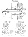
- Fig. 1(a) is a schematic illustration of a section of a pulverized coal burner of the present embodiment
- Figs. 1(b) and 1(c) each are an enlarged view of a part of Fig. 1(a) for explaining air flow and recirculating zone in a nozzle end region shown in Fig. 1(a).
- 10 denotes a pulverized coal nozzle which is connected to a transfer tube (not shown) at an upstream side and transfers and supplies pulverized coals together with primary air.
- 11 denotes a secondary air nozzle for jetting secondary air.
- the secondary air nozzle 11 has a flow path formed around the outer periphery of the pulverized coal nozzle 10 and shaped in a circular cross-section which is concentric with the pulverized coal nozzle 10.
- tertiary air nozzle for jetting tertiary air, which has a flow path formed around the outer periphery of the secondary air nozzle 11 and shaped in a circular cross-section which is concentric with the secondary air nozzle 11.
- a flow rate distribution among primary air, secondary air and tertiary air is 1-2: 1: 3-7, for example, and the distribution is made so that the pulverized coals are completely burnt by the tertiary air.
- 13 denotes inflowing pulverized coals and primary air.
- 14 and 15 denote inflowing secondary air and tertiary air, respectively.
- 16 denotes an oil gun provided in the pulverized coal nozzle 10 so as to axially extend to a position in the vicinity of the outlet of the nozzle 10.
- the oil gun 16 is used for assisting combustion at the time of burner starting or low load combustion.
- 17 denotes a venturi tube making small the inner diameter of the pulverized coal nozzle 10 to prevent the pulverized coals from backfiring.
- 18 denotes a flame stabilizing ring provided at the end of a partition wall 28 partitioning the pulverized coal nozzle 10 and the secondary air nozzle 11 and separating the primary air and secondary air to expand a recirculating zone 31.
- 19 denotes a burner throat forming a furnace wall and served also as an outer peripheral wall of the tertiary nozzle 12.
- 20 denotes a guide sleeve provided at the end of a partition wall 21 separating the secondary air nozzle 11 and the tertiary air nozzle 12, which sleeve also is referred to as a tube expanded portion in the present invention.
- 22 denotes a swirler for swirling tertiary air along the periphery of the secondary air nozzle 11.
- the swirler 22 employs air swirling vanes usually called as resistor vanes in this embodiment.
- 23 denotes a side plate for inflowing secondary air.
- 24 denotes water pipes provided on the furnace wall 19.
- 25 denotes a wind box in which secondary air is introduced.
- 26 denotes a damper for adjusting secondary air.
- FIG. 27 denotes a swirler for swirling secondary air along the periphery of the pulverized coal nozzle, and the swirler 27 employs air swirling vanes usually called as vanes in this embodiment.
- 28 denotes the partition wall between the pulverized coal nozzle 10 and the secondary air nozzle 11.
- 30 denotes a guide plate provided at the end of the inner peripheral wall of the secondary air nozzle 11 for jetting the secondary air toward the radially outer side.
- 31 denotes the recirculating zones formed between jetting regions of the pulverized coal nozzle 10 and the secondary air nozzle 11.
- 52 denotes a secondary air flow.
- 53 denotes a tertiary air flow.
- 65a denotes an obstacle (for flow path narrowing) which is a part of the flame stabilizing ring 18 and provided in the inner peripheral portion of the secondary air nozzle 11.
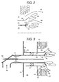
- Fig. 2 is an enlarged view for explaining air flows and recirculating zones in a nozzle end region of a conventional pulverized coal burner, which is shown for comparing it with the pulverized coal burner in Fig. 1(b).
- the structure shown in Fig. 2 differs from that shown in Fig. 1(a) in that the guide plate is not provided.
- the pulverized coal burner starts up combustion, since the air downstream of the partition wall 28 is taken in the the air jetted from each nozzle, the pressure downstream of the partition wall 28 decreases, and a recirculating zone 31 is formed. Since the flame stabilizing ring 18 is provided at the end portion of the partition wall 28, primary air and secondary air are separated from each other, and the recirculating zone 31 expands. Since a high temperature gas stays within the recirculating zone 31, ignition of pulverized coals progresses, the stability of flame is improved. Thereby, the flame is stably formed by pulverized coals and primary air in the vicinity of the outlet of the pulverized coal nozzle 10.
- a NOx reducing zone expands and it is possible to decrease an amount of NOx formation.
- unburnt carbon in combustion ashes left after combustion decreases.
- the swirlers 22, 27 are provided, secondary air and tertiary air are jetted as swirling flows, the negative pressure downstream of the flame stabilizing ring 18 is raised by the centrifugal force of the air, the recirculating zone expands further. Thereby, mixing of the secondary air and tertiary air with the pulverized coals in the vicinity of the burner is delayed, and the concentration of oxygen within the flame decreases, so that the NOx reducing zone expands.
- the guide plate 30 is provided at the end portion of the inner peripheral wall of the secondary air nozzle 11 as a means for deflecting a secondary air flow 52 jetted from the secondary air nozzle 11 toward the radially outer side, the secondary air is jetted in a direction of an radially outer side, the mixing of the secondary air and tertiary air with the pulverized coals is delayed further, and the recirculating zone downstream of the flame stabilizing ring 18 expands. Therefore, the combustion of the pulverized coals in this recirculating zone region is promoted, NOx formtion and unburnt carbon can be decreased further.
- the flow path of tertiary air 53 is bent by the guide sleeve 20 formed in a tapered cylindrical shape, and the tertiary air is jetted outward.
- the flow path of the secondary air nozzle 11 is expanded outward at the nozzle outlet by the guide sleeve 20. Since air flows straightly by its inertia, secondary air is apt to flow along the burner axis (a dashed line in Fig. 2), and there occurs a pressure drop in a reverse direction (hereunder, referred to as adverse pressure gradient) to a jetting direction of air flow along the guide sleeve 20, whereby a recirculating zone 54 is formed downstream of the guide sleeve 20.
- secondary air 52 is jetted in an outer peripheral direction by the guide plate 30. Therefore, formation of a recirculating zone at a downstream side of the guide sleeve 20 separating the secondary air nozzle 11 and the tertiary air nozzle 12 is prevented or suppressed. Further, in particular, since the burner is constructed so that the secondary air 52 is jetted more outward than tertiary air 53, the flow of the tertiary air 53 is further directed to the outer peripheral direction by the momentum of secondary air 52 jetted in the outer peripheral direction. Therefore, mixing of the secondary air and tertiary air with the pulverized coals in the vicinity of burner is delayed, the concentration of oxygen within the flame is lowered, and the NOx reducing zone expands, whereby NOx occurred within the flame can be decreased.
- the tip of the guide plate 30 is disposed closer to the burner axis (a dashed line in Fig. 1(b)) side than the tip of the guide sleeve 20, the secondary air is apt to flow more outward and a recirculating zone is unlikely to occur downstream of the guide sleeve 20.
- the flow path of the secondary air nozzle 11 is narrowed near its outlet by the flame stabilizing ring 18, whereby the secondary air made larger in flow velocity by the flow path narrowing is jetted, so that tertiary air can be further delayed in mixting with coal.
- secondary air is jetted in the radially outer direction from the secondary air nozzle 11 by the guide plate 30 provided on the secondary air nozzle 11. Further, the adverse pressure gradient at the downstream side of the partition wall 21 between the secondary air nozzle 11 and the tertiary air nozzle 12 becomes small, so that tertiary air also is jetted in the radially outer direction from the tertiary air nozzle 12 disposed at the outer periphery side of the secondary air nozzle 11. Therefore, mixing of pulverized coal and combustion air with pulverized coals in the vicinity of the burner is suppressed, the pulverized coals are burnt in the vicinity of the burner under the condition of low oxygen concentration, whereby an amount of NOx formation can be reduced.
- a combustion test was conducted in a combustion furnace (500 kg/h), using the pulverized coal burner (a distance between the guide sleeve 20 and the guide plate 30 is 10 mm) as shown in Figs. 1(a) and 1(b) and the burner shown in Fig. 2.
- the result is shown in a table 1.
- the concentration of NOx after combustion by the burner of Figs. 1(a) and 1(b) was 103 ppm (6 vol% O 2 ), while the NOx concentration by the burner of Fig. 2 was 111 ppm (6 vol% O 2 ).
- An effect of decreasing a NOx formation amount by the present invention was acknowledged.
- Fig. 1(c) is an enlarged view of a nozzle end portion for explaining an air flow in a case where the guide plate 30 in Fig. 1(b) is shifted toward an upstream side.
- secondary air 52 flows as shown in Fig. 1(c). That is, the secondary air 52 is changed outward in its flow direction by the guide plate 30, however, the flow toward a radially outer side is prevented by the sleeve 20.
- the secondary air jetted from the burner flows directed more to a direction of the central axis than in the case where the guide plate 30 is arranged at a more downstream side in the burner axis direction than the tip of the guide sleeve 20 as shown in Fig. 1(b). Therefore, as shown in Fig. 1(c), a recirculating zone 54 is apt to be formed in a downstream side of the guide sleeve 20. Flows are induced in the tertiary air 53 by the recirculating zone 54. Since the flows toward the central axis are apt to be induced in the tertiary air 53, mixing between the tertiary air and the pulverized coals is advanced in time and a NOx reducing zone is narrowed.
- Fig. 3 is a sectional view of a pulverized coal burner of the second embodiment.
- This embodiment is different from the first embodiment of Figs. 1(a) and 1(b) in that an angle 55 of the guide plate 30 and an angle 56 of the guide sleeve 20 each are made adjustable, and the other structure is the same as that of the first embodiment.
- the angles of the guide plate 30 and guide sleeve 20 are adjusted depending on supply amounts of pulverized coal, primary air and combustion air, whereby it is possible to form a further suitable recirculating zone region and effectively decrease NOx and unburnt carbon, as compared with the first embodiment.
- the angle 55 of the guide plate 30 is set to 60-90° , preferably 80-90° , it is possible to prevent formation of recirculating zone between secondary air and tertiary air, and to form a large recirculating zone at a downstream side of the guide plate 30.
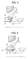
- FIG. 4 A third embodiment of the present invention is described, referring to Fig. 4.
- Fig. 4 is a sectional view of a nozzle end portion of a pulverized coal burner of the present embodiment.
- the embodiment is characterized in that a taper shaped ring 61 is provided in an output region of the secondary air nozzle 11 as an induction member for inducing or guiding an air flow jetted from the secondary air nozzle 11 to the radially outer side of the secondary air nozzle 11, as shown in Fig. 4.
- the other structure is approximately the same as that of the first embodiment.
- tertiary air 53 flows toward the outer periphery, mixing of secondary air and tertiary air with pulverized coal in the vicinity of the burner is delayed, the concentration of oxygen within flame decreases, and a NOx reducing zone within the flame expands, whereby it is possible to effectively decrease NOx and unburnt carbon.
- a fourth embodiment of the present invention is described, referring to Fig. 5.
- Fig. 5 is a sectional view of a nozzle end portion of a pulverized coal burner of the present embodiment.
- the present embodiment is characterized in that a gas jet nozzle 63 for jetting a gas toward the radially outer side is provided within the secondary air nozzle 11 or in a region of the nozzle outlet as a means for deflecting a secondary air flow jetted from the secondary air nozzle 11 toward the radially outer side of the secondary air nozzle 11, as shown in Fig. 5.
- the other structure is approximately the same as that of the first embodiment.
- the gas air, combustion exhaust gas, inert gas such as nitrogen, steam, etc. can be used.
- secondary air jetted from the secondary air nozzle 11 flows along the outer periphery by the momentum of the gas jetted from the gas jet nozzle 63.
- the flow velocity of gas jetted from the gas jet nozzle 63 is faster than the flow velocity of air jetted from the secondary air nozzle 11.
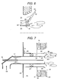
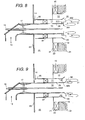
- a fifth embodiment of the present invention is described, referring to Fig. 6.
- Fig. 6 is a sectional view of a nozzle end portion of a pulverized coal burner of this embodiment.
- the present embodiment is characterized in that swirling vanes 64 as a swirler for secondary air are provided in the outlet of the secondary air nozzle 11 as a means for deflecting a secondary air flow jetted from the secondary air nozzle 11 toward the radially outer side of the secondary air nozzle 11, as shown in Fig. 6.
- the other structure is approximately the same as that of the first embodiment.
- the secondary air is swirled by the swirling vanes 64 and flows deflected toward the radially outer side by centrifugal force. Thereby, the secondary air is jetted toward the radially outer side along the guide sleeve 20, and guided to the radially outer side, whereby a more suitable recirculating zone region is formed and it is possible to effectively decrease NOx and unburnt carbon.
- air flowing along the recirculating zone changes in flow direction by the adverse pressure gradient and air flowing outside the recirculating zone is apt to flow toward the primary air side.
- the secondary air since the secondary air is jetted toward the radially outer side, the primary air and secondary air are separated from each other and flow as they are separated. Therefore, the adverse pressure gradient becomes strong at the downstream side of the partition wall of the pulverized coal nozzle and the secondary air nozzle, and the recirculating zone formed in the region of the adverse pressure gradient expands.
- a high temperature gas stays, stabilizes the ignition of pulverized coal and flame. Expansion of the recirculating zone promotes ignition of pulverized coal by the high temperature gas. Since consumption of oxygen progresses by the ignition, a region of low oxygen concentration atmosphere within the flame expands, whereby it is possible to decrease an amount of NOx formation and an anount of unburnt carbon in the combustion ashes.
- FIG. 7 A sixth embodiment of the present invention is described, referring to Fig. 7.
- Fig. 7 is a sectional view of a pulverized coal burner of the present embodiment.
- the embodiment is characterized in that a ring 30 having a plane perpendicular to directions of a primary air flow and secondary air flow is provided at the end portion of the partition wall 28 as a means for deflecting a secondary air flow jetted from the secondary air nozzle 11 to the radially outer side of the secondary air nozzle 11 and forming a recirculating zone at a downstream side of the partition wall 28, as shown in Fig. 7.
- the other structure is approximately the same as that of the first embodiment.
- the ring 30 is formed of an inner ring 301 formed at the side of the pulverized coal nozzle 10 and an outer ring 302 formed in the side of the secondary air nozzle 11.
- the ring 30 causes turbulence in the primary air and secondary air by the ring 30, whereby the recirculating zone formed downstream of the ring 30 develops.
- the positions of the inner ring 301 and outer ring 302 are separated from each other in the flow direction.
- the recirculating zone region can be expanded, and the region of low oxygen concentration atmosphere within the flame also can be expanded, so that an amount of NOx formation and an amount of unburnt carbon in the combustion ashes can be effectively decreased.
- a seventh embodiment of the present invention is described, referring to Fig. 8.
- Fig. 8 is a sectional view of a pulverized coal burner of the present embodiment.
- the embodiment is characterized in that the ring 30 provided at the end portion of the partition wall 28 is provided with a large thickness portion 303 (10 mm thick, for example) at the secondary air nozzle inner wall side of the ring 30, as a means for deflecting a secondary air flow jetted from the secondary air nozzle 11 to the radially outer side of the secondary air nozzle 11 and forming a recirculating zone at a downstream side of the partition wall 28, as shown in Fig. 8.
- the other structure is approximately the same as that of the sixth embodiment.
- the flow path of the secondary air nozzle 11 is narrowed by the large thickness portion 303, the secondary air is made faster in velocity when the air passes at the large thickness portion 303, the air impinges on the outer ring 302, and then it is jetted to radially outer side.
- the outer ring 302 of the ring 30 is made in a uniform ring, however, the outer ring 302 can be made in notched shape or concavo-convex shape at the peripheral portion of the end portion thereof, when necessary. By forming it in such a shape, thermal deformation of the ring can be damped, further, the turbulence downstream of the outer ring 302 increases, and the recirculating zone develops further. Further, the concavo-convex notch can be formed in the inner ring 301 side in addition to the outer ring 302.
- Fig. 9 is a sectional view of a pulverized coal burner of the present embodiment.
- the embodiment is characterized in that the ring 30 is provided as a means for deflecting a secondary air flow jetted from the secondary air nozzle 11 to the outer periphery side of the secondary air nozzle 11 and forming a recirculating zone at a downstream side of the partition wall 28, and a plurality of narrowing portions 65b narrowing the flow path in the vicinity of the outlet of the secondary air nozzle 11 is provided in the peripheral direction, as shown in Fig. 9.
- the other structure is approximately the same as that of the sixth embodiment.
- the secondary air is made faster in velocity by the narrowing portions 65b, and the air flow is disturbed by an expanded portion without the narrowing portions 65b, whereby it is possible to generate a constant turbulence of relatively large frequency. Therefore, the recirculating zone 31 formed at the downstream side develops. Further, the secondary air the velocity of which is increased by the narrowing portions 65b impinges on the outer ring 302, whereby the velocity of flow directed to the radially outer side can be increased.
- the secondary air is separated from the pulverized coal flowing at a burner central portion, and mixing of the secondary air tertiary air with the pulverized coal can be delayed, thereby the NOx reducing zone within flame expands, an amount of NOx formation and unburnt carbon in the combustion ashes can be effectively decreased, and it is possible to improve the ignition of pulverized coal and the stability of flame.
- the flow shift means for deflecting the secondary air jetted from the secondary air nozzle toward the radially outer side of the secondary air nozzle is provided, the secondary air flows toward the radially outer side, the recirculating zone formed downstream of the partition wall between the pulverized coal nozzle and the secondary air nozzle moves toward the radially outer side, and the scale thereof also can be enlarged.
- mixing of pulverized coal and secondary air, tertiary air in the vicinity of the burner is suppressed, the pulverized coal burns under the condition of low oxygen concentration atmosphere in the vicinity of the burner, and NOx formation can be effectively decreased.
Landscapes
- Engineering & Computer Science (AREA)
- Chemical & Material Sciences (AREA)
- Combustion & Propulsion (AREA)
- Mechanical Engineering (AREA)
- General Engineering & Computer Science (AREA)
Applications Claiming Priority (3)
| Application Number | Priority Date | Filing Date | Title |
|---|---|---|---|
| JP19848997A JP3344694B2 (ja) | 1997-07-24 | 1997-07-24 | 微粉炭燃焼バーナ |
| JP19848997 | 1997-07-24 | ||
| EP98113187A EP0893649B1 (fr) | 1997-07-24 | 1998-07-15 | Brûleur à charbon pulvérisé |
Related Parent Applications (1)
| Application Number | Title | Priority Date | Filing Date |
|---|---|---|---|
| EP98113187A Division EP0893649B1 (fr) | 1997-07-24 | 1998-07-15 | Brûleur à charbon pulvérisé |
Publications (2)
| Publication Number | Publication Date |
|---|---|
| EP1376009A2 true EP1376009A2 (fr) | 2004-01-02 |
| EP1376009A3 EP1376009A3 (fr) | 2004-01-14 |
Family
ID=16391976
Family Applications (3)
| Application Number | Title | Priority Date | Filing Date |
|---|---|---|---|
| EP03017217A Withdrawn EP1376009A3 (fr) | 1997-07-24 | 1998-07-15 | Brûleur à charbon pulverisé |
| EP98113187A Expired - Lifetime EP0893649B1 (fr) | 1997-07-24 | 1998-07-15 | Brûleur à charbon pulvérisé |
| EP03014608A Expired - Lifetime EP1351017B1 (fr) | 1997-07-24 | 1998-07-15 | Brûleur à charbon pulvérisé |
Family Applications After (2)
| Application Number | Title | Priority Date | Filing Date |
|---|---|---|---|
| EP98113187A Expired - Lifetime EP0893649B1 (fr) | 1997-07-24 | 1998-07-15 | Brûleur à charbon pulvérisé |
| EP03014608A Expired - Lifetime EP1351017B1 (fr) | 1997-07-24 | 1998-07-15 | Brûleur à charbon pulvérisé |
Country Status (11)
| Country | Link |
|---|---|
| US (1) | US6112676A (fr) |
| EP (3) | EP1376009A3 (fr) |
| JP (1) | JP3344694B2 (fr) |
| KR (1) | KR100309667B1 (fr) |
| CN (1) | CN1246626C (fr) |
| AU (1) | AU716261B2 (fr) |
| CA (1) | CA2243376C (fr) |
| CZ (1) | CZ291689B6 (fr) |
| DE (2) | DE69834960T2 (fr) |
| PL (1) | PL190938B1 (fr) |
| TW (1) | TW357244B (fr) |
Families Citing this family (68)
| Publication number | Priority date | Publication date | Assignee | Title |
|---|---|---|---|---|
| JP3551006B2 (ja) * | 1998-02-26 | 2004-08-04 | 住友電気工業株式会社 | 光ファイバ用多孔質母材の製造方法 |
| JP2000257811A (ja) * | 1999-03-03 | 2000-09-22 | Hitachi Ltd | 微粉炭燃焼方法及び微粉炭燃焼装置並びに微粉炭燃焼バーナ |
| US6367288B1 (en) * | 1999-12-29 | 2002-04-09 | Corning Incorporated | Method and apparatus for preventing burner-hole build-up in fused silica processes |
| CZ303467B6 (cs) * | 2000-08-04 | 2012-10-03 | Babcock-Hitachi Kabushiki Kaisha | Horák na pevné palivo a zpusob regulace spalování uskutecneného tímto horákem |
| US6474250B1 (en) * | 2001-05-24 | 2002-11-05 | Babcock Borsig Power, Inc. | Nozzle assembly for a pulverized coal burner |
| US7163392B2 (en) * | 2003-09-05 | 2007-01-16 | Feese James J | Three stage low NOx burner and method |
| US7241322B2 (en) * | 2003-11-21 | 2007-07-10 | Graham Robert G | Pyrolyzing gasification system and method of use |
| AU2005221152A1 (en) * | 2004-03-08 | 2005-09-22 | Joel Vatsky | Low nox and enhanced flame stabilization |
| JP4261401B2 (ja) * | 2004-03-24 | 2009-04-30 | 株式会社日立製作所 | バーナと燃料燃焼方法及びボイラの改造方法 |
| KR100676868B1 (ko) | 2004-10-13 | 2007-02-02 | 한국생산기술연구원 | 초저질소산화물 연소기 |
| JP4309853B2 (ja) | 2005-01-05 | 2009-08-05 | バブコック日立株式会社 | 固体燃料バーナおよび燃焼方法 |
| DE102005032109B4 (de) * | 2005-07-07 | 2009-08-06 | Hitachi Power Europe Gmbh | Kohlenstaubbrenner für niedrige NOx-Emissionen |
| US8656846B2 (en) * | 2006-05-01 | 2014-02-25 | Energy Technologies, Inc. | Continuous real time heating value (BTU)/coal flow balancing meter |
| US8113824B2 (en) * | 2006-06-01 | 2012-02-14 | Babcock & Wilcox Power Generation Group, Inc. | Large diameter mid-zone air separation cone for expanding IRZ |
| US7810441B2 (en) * | 2006-07-21 | 2010-10-12 | Astec, Inc. | Coal burner assembly |
| KR101285447B1 (ko) * | 2006-09-27 | 2013-07-12 | 바브콕-히다찌 가부시끼가이샤 | 버너, 버너를 구비한 연소장치 및 보일러 |
| US7832212B2 (en) * | 2006-11-10 | 2010-11-16 | General Electric Company | High expansion fuel injection slot jet and method for enhancing mixing in premixing devices |
| ITAN20060075A1 (it) * | 2006-12-22 | 2008-06-23 | Merloni Termosanitari Spa | Gruppo di combustione per generatore di calore cui e' associato un ulteriore generatore di calore |
| US20080280238A1 (en) * | 2007-05-07 | 2008-11-13 | Caterpillar Inc. | Low swirl injector and method for low-nox combustor |
| CN100549519C (zh) * | 2007-09-25 | 2009-10-14 | 深圳东方锅炉控制有限公司 | 一种旋流煤粉燃烧器 |
| CN101216173B (zh) * | 2007-12-26 | 2011-01-19 | 东方锅炉(集团)股份有限公司 | 一种双旋流粉煤燃烧器 |
| EP2080952A1 (fr) * | 2008-01-17 | 2009-07-22 | L'AIR LIQUIDE, Société Anonyme pour l'Etude et l'Exploitation des Procédés Georges Claude | Brûleur et procédé pour alterner une oxycombustion et une combustion à l'air |
| JP5022248B2 (ja) * | 2008-01-23 | 2012-09-12 | 三菱重工業株式会社 | ボイラ構造 |
| US20090297996A1 (en) * | 2008-05-28 | 2009-12-03 | Advanced Burner Technologies Corporation | Fuel injector for low NOx furnace |
| US20100021853A1 (en) * | 2008-07-25 | 2010-01-28 | John Zink Company, Llc | Burner Apparatus And Methods |
| JP5332389B2 (ja) | 2008-08-08 | 2013-11-06 | 株式会社Ihi | バーナ |
| WO2010034124A1 (fr) * | 2008-09-29 | 2010-04-01 | New Brunswick Power Generation Corporation | Système et procédé pour brûler du combustible |
| US20100081100A1 (en) * | 2008-10-01 | 2010-04-01 | Wessex Incorporated | Burner Tips |
| US9121609B2 (en) * | 2008-10-14 | 2015-09-01 | General Electric Company | Method and apparatus for introducing diluent flow into a combustor |
| KR100964307B1 (ko) | 2008-10-22 | 2010-06-16 | 두산중공업 주식회사 | 미분탄 버너 |
| US8177145B2 (en) * | 2008-11-04 | 2012-05-15 | General Electric Company | Feed injector system |
| JP5369899B2 (ja) | 2009-05-27 | 2013-12-18 | 株式会社Ihi | バーナ |
| CN101561138B (zh) * | 2009-05-27 | 2010-12-08 | 哈尔滨工业大学 | 二次浓缩双喷口微油量点燃煤粉装置 |
| KR101112099B1 (ko) | 2010-05-20 | 2012-02-22 | (주)금강씨엔티 | 시멘트 소성로 가열장치 |
| CN102062396B (zh) * | 2010-10-13 | 2013-01-02 | 西安交通大学 | 一种复合浓淡三调风低NOx旋流煤粉燃烧器 |
| CN102313281A (zh) * | 2011-07-22 | 2012-01-11 | 浙江百能科技有限公司 | 一种降低燃煤锅炉三次风燃烧生成的氮氧化物的方法 |
| JP5794419B2 (ja) * | 2011-07-29 | 2015-10-14 | 三菱日立パワーシステムズ株式会社 | 固体燃料バーナ |
| SE1450256A1 (sv) * | 2011-08-10 | 2014-03-06 | Fives North American Comb Inc | EN LÅG-NOx-BRÄNSLEINJICERING FÖR EN HÄRDUGN |
| PL2592341T3 (pl) * | 2011-11-09 | 2017-09-29 | Fortum Oyj | Palnik sproszkowanego paliwa |
| CN102679339B (zh) * | 2012-06-05 | 2014-05-07 | 唐山市金沙工贸有限公司 | 煤粉燃烧器 |
| CN103836621B (zh) * | 2012-11-21 | 2016-08-03 | 烟台龙源电力技术股份有限公司 | 一种分级燃烧的低氮氧化物旋流燃烧器 |
| CN103017163A (zh) * | 2012-12-31 | 2013-04-03 | 西安航天远征流体控制股份有限公司 | 一种新型粉煤烧嘴旋流雾化装置 |
| CN103134050B (zh) * | 2013-03-07 | 2015-04-08 | 上海锅炉厂有限公司 | 一种带有间隙风的多煤种低氮煤粉燃烧装置 |
| CN103411215B (zh) * | 2013-08-26 | 2016-01-27 | 中节环立为(武汉)能源技术有限公司 | 多向射流式旋流煤粉燃烧器 |
| CN103672884A (zh) * | 2013-12-27 | 2014-03-26 | 安其云 | 新型高效低氮全自动煤粉燃烧器 |
| EP3026338B1 (fr) * | 2014-11-28 | 2020-02-26 | General Electric Technology GmbH | Système de combustion d'une chaudière |
| CN104501205B (zh) * | 2014-12-25 | 2017-04-05 | 中国科学院长春光学精密机械与物理研究所 | 一种便于改造的长寿命w火焰锅炉拱上布置微油点火装置 |
| US20160223196A1 (en) * | 2015-02-02 | 2016-08-04 | The Government Of The United States Of America, As Represented By The Secretary Of The Navy | Crude Oil Spray Combustor |
| JP6231047B2 (ja) * | 2015-06-30 | 2017-11-15 | 三菱日立パワーシステムズ株式会社 | 固体燃料バーナ |
| CN105737145B (zh) * | 2016-02-26 | 2017-11-03 | 郑州轻工业学院 | 一种强化浓缩型旋流煤粉燃烧器 |
| CN107152678B (zh) * | 2016-03-02 | 2019-08-30 | 山西三合盛节能环保技术股份有限公司 | 一种增强分流增浓的煤粉解耦燃烧器及燃烧方法 |
| JP6737005B2 (ja) * | 2016-06-27 | 2020-08-05 | 株式会社Ihi | バーナ |
| CN106090902B (zh) * | 2016-08-11 | 2018-04-06 | 东方电气集团东方锅炉股份有限公司 | 环形回流型褐煤旋流燃烧器及燃烧方法 |
| JP6797714B2 (ja) * | 2017-02-22 | 2020-12-09 | 三菱パワー株式会社 | 燃焼装置 |
| CN107726310A (zh) * | 2017-11-22 | 2018-02-23 | 北京神雾电力科技有限公司 | 一种新型旋流煤粉燃烧器 |
| WO2019131335A1 (fr) | 2017-12-26 | 2019-07-04 | 三菱日立パワーシステムズ株式会社 | Brûleur à combustible solide et stabilisateur de flamme pour brûleur à combustible solide |
| AU2018423543B2 (en) | 2018-05-17 | 2022-03-17 | Mitsubishi Power, Ltd. | Support-sleeve protective member and solid fuel burner provided with same |
| JP6813533B2 (ja) | 2018-05-22 | 2021-01-13 | 三菱パワー株式会社 | バーナおよび燃焼装置 |
| CN108613184B (zh) * | 2018-06-14 | 2023-10-13 | 华能国际电力股份有限公司 | 一种可调节负荷的燃烧器及工作方法 |
| WO2020234965A1 (fr) * | 2019-05-20 | 2020-11-26 | 三菱日立パワーシステムズ株式会社 | Brûleur à combustible solide |
| MY210172A (en) * | 2019-05-13 | 2025-08-30 | Mitsubishi Power Ltd | Solid fuel burner, boiler equipment, nozzle unit for solid fuel burner, and guide vane unit |
| CN111947141B (zh) * | 2020-08-13 | 2023-05-30 | 西安交通大学 | 一种可调节的风-煤逐级混合低NOx燃烧装置 |
| CN112178633A (zh) * | 2020-09-29 | 2021-01-05 | 湖北赤焰热能工程有限公司 | 一种浓缩型双调风旋流燃烧器及方法 |
| CN114060843B (zh) * | 2021-12-02 | 2025-07-15 | 中国石油化工股份有限公司 | 一种分布式多型面烟气注入分级低氮燃烧设备 |
| JP7834474B2 (ja) * | 2021-12-27 | 2026-03-24 | 川崎重工業株式会社 | バーナ及び燃焼炉 |
| CN114738742B (zh) * | 2022-04-19 | 2023-09-22 | 东方电气集团东方锅炉股份有限公司 | 一种扩锥角度可变的旋流燃烧器 |
| CN116951315B (zh) * | 2023-07-05 | 2025-11-04 | 中国矿业大学 | 一种适用于co2输送管道的放空装置 |
| CN116989353B (zh) * | 2023-07-28 | 2025-09-30 | 杭州电子科技大学 | 一种电站锅炉低压电弧点火稳燃装置及方法 |
Family Cites Families (32)
| Publication number | Priority date | Publication date | Assignee | Title |
|---|---|---|---|---|
| US4241673A (en) * | 1979-11-05 | 1980-12-30 | Combustion Engineering, Inc. | Direct ignition of pulverized coal |
| JPS6026922B2 (ja) * | 1980-02-25 | 1985-06-26 | 川崎重工業株式会社 | 微粉炭バ−ナ |
| JPS5986809A (ja) * | 1982-11-09 | 1984-05-19 | Babcock Hitachi Kk | 還元炎形成用微粉炭バ−ナ |
| JPS60226609A (ja) * | 1984-04-23 | 1985-11-11 | Babcock Hitachi Kk | 燃焼装置 |
| US4602571A (en) * | 1984-07-30 | 1986-07-29 | Combustion Engineering, Inc. | Burner for coal slurry |
| US4539918A (en) * | 1984-10-22 | 1985-09-10 | Westinghouse Electric Corp. | Multiannular swirl combustor providing particulate separation |
| DE3520781A1 (de) * | 1985-06-10 | 1986-12-11 | Stubinen Utveckling AB, Stockholm | Verfahren und vorrichtung zum verbrennen fluessiger und/oder fester brennstoffe in pulverisierter form |
| EP0233680B2 (fr) * | 1986-01-08 | 1993-10-27 | Hitachi, Ltd. | Procédé et dispositif pour la combustion d'un mélange charbon/eau |
| JPS62172105A (ja) * | 1986-01-24 | 1987-07-29 | Hitachi Ltd | NOxを抑制する燃焼方法及び装置 |
| JPH0754162B2 (ja) * | 1986-05-26 | 1995-06-07 | 株式会社日立製作所 | 低NOx燃焼用バ−ナ |
| JP2526236B2 (ja) * | 1987-02-27 | 1996-08-21 | バブコツク日立株式会社 | 超低NOx燃焼装置 |
| JP2641738B2 (ja) * | 1987-10-07 | 1997-08-20 | バブコツク日立株式会社 | 微粉炭燃焼装置 |
| EP0343767B1 (fr) * | 1988-03-04 | 1994-01-19 | Northern Engineering Industries Plc | Brûleur à combustible pulvérisé |
| JP2776572B2 (ja) * | 1989-07-17 | 1998-07-16 | バブコツク日立株式会社 | 微粉炭バーナ |
| JP2781222B2 (ja) | 1989-09-25 | 1998-07-30 | バブコツク日立株式会社 | 微粉炭燃焼装置 |
| JP2954628B2 (ja) * | 1990-01-17 | 1999-09-27 | バブコツク日立株式会社 | 微粉炭バーナ |
| EP0445938B1 (fr) * | 1990-03-07 | 1996-06-26 | Hitachi, Ltd. | Brûleur à charbon pulvérisé, chaudière au charbon pulvérisé et procédé pour la combustion de charbon pulvérisé |
| DE69130927T2 (de) * | 1990-06-29 | 1999-06-24 | Babcock-Hitachi K.K., Tokio/Tokyo | Verbrennungsvorrichtung |
| US5603906A (en) * | 1991-11-01 | 1997-02-18 | Holman Boiler Works, Inc. | Low NOx burner |
| RU2038535C1 (ru) * | 1992-04-23 | 1995-06-27 | Акционерное общество "Котэс" | Пылеугольная горелка с низким выходом оксидов азота |
| RU2062946C1 (ru) * | 1993-07-17 | 1996-06-27 | Государственное предприятие по наладке, совершенствованию технологии и эксплуатации электростанций и сетей "Уралтехэнерго" | Пылеугольная горелка |
| DE4395243T1 (de) * | 1993-11-08 | 1996-11-21 | Ivo International Oy | Verfahren und Vorrichtung zum Verbrennen von pulverförmigem Brennmaterial |
| US5700143A (en) * | 1994-01-24 | 1997-12-23 | Hauck Manufacturing Company | Combination burner with primary and secondary fuel injection |
| JPH07260106A (ja) * | 1994-03-18 | 1995-10-13 | Hitachi Ltd | 微粉炭燃焼バーナ及び微粉炭燃焼装置 |
| JP3140299B2 (ja) * | 1994-06-30 | 2001-03-05 | 株式会社日立製作所 | 微粉炭バーナ及びその使用方法 |
| US5680823A (en) | 1995-03-22 | 1997-10-28 | The Babcock & Wilcox Company | Short flame XCL burner |
| US5625991A (en) * | 1995-06-07 | 1997-05-06 | Shape Corporation | Multiple panel assembly and connector assembly therefor |
| JP2756098B2 (ja) * | 1995-07-14 | 1998-05-25 | 川崎重工業株式会社 | 微粉炭バーナ |
| DE19607676A1 (de) * | 1996-02-29 | 1997-09-11 | Steinmueller Gmbh L & C | Brenner und mit mindestens einem Brenner betriebene Feuerungsanlage |
| JP3099109B2 (ja) * | 1996-05-24 | 2000-10-16 | 株式会社日立製作所 | 微粉炭バーナ |
| AU709979B2 (en) * | 1996-07-19 | 1999-09-09 | Mitsubishi Hitachi Power Systems, Ltd. | Combustion burner and combustion device provided with same |
| US5829369A (en) * | 1996-11-12 | 1998-11-03 | The Babcock & Wilcox Company | Pulverized coal burner |
-
1997
- 1997-07-24 JP JP19848997A patent/JP3344694B2/ja not_active Expired - Lifetime
-
1998
- 1998-07-14 TW TW087111444A patent/TW357244B/zh not_active IP Right Cessation
- 1998-07-14 AU AU76156/98A patent/AU716261B2/en not_active Expired
- 1998-07-15 DE DE69834960T patent/DE69834960T2/de not_active Expired - Fee Related
- 1998-07-15 EP EP03017217A patent/EP1376009A3/fr not_active Withdrawn
- 1998-07-15 EP EP98113187A patent/EP0893649B1/fr not_active Expired - Lifetime
- 1998-07-15 DE DE69819615T patent/DE69819615T2/de not_active Expired - Lifetime
- 1998-07-15 US US09/115,736 patent/US6112676A/en not_active Expired - Fee Related
- 1998-07-15 EP EP03014608A patent/EP1351017B1/fr not_active Expired - Lifetime
- 1998-07-21 CZ CZ19982283A patent/CZ291689B6/cs not_active IP Right Cessation
- 1998-07-23 KR KR1019980029713A patent/KR100309667B1/ko not_active Expired - Lifetime
- 1998-07-23 PL PL327683A patent/PL190938B1/pl unknown
- 1998-07-23 CN CNB981174248A patent/CN1246626C/zh not_active Expired - Lifetime
- 1998-07-24 CA CA002243376A patent/CA2243376C/fr not_active Expired - Lifetime
Also Published As
| Publication number | Publication date |
|---|---|
| EP1351017B1 (fr) | 2006-06-14 |
| DE69834960T2 (de) | 2006-12-28 |
| JP3344694B2 (ja) | 2002-11-11 |
| CZ291689B6 (cs) | 2003-05-14 |
| AU7615698A (en) | 1999-02-04 |
| DE69834960D1 (de) | 2006-07-27 |
| CA2243376C (fr) | 2003-12-23 |
| EP0893649A3 (fr) | 1999-09-15 |
| PL190938B1 (pl) | 2006-02-28 |
| DE69819615T2 (de) | 2004-09-30 |
| US6112676A (en) | 2000-09-05 |
| PL327683A1 (en) | 1999-02-01 |
| CN1246626C (zh) | 2006-03-22 |
| EP0893649B1 (fr) | 2003-11-12 |
| KR19990014119A (ko) | 1999-02-25 |
| EP1351017A3 (fr) | 2004-01-28 |
| AU716261B2 (en) | 2000-02-24 |
| CA2243376A1 (fr) | 1999-01-24 |
| JPH1144411A (ja) | 1999-02-16 |
| EP1376009A3 (fr) | 2004-01-14 |
| EP0893649A2 (fr) | 1999-01-27 |
| CN1206808A (zh) | 1999-02-03 |
| KR100309667B1 (ko) | 2001-12-12 |
| EP1351017A2 (fr) | 2003-10-08 |
| DE69819615D1 (de) | 2003-12-18 |
| TW357244B (en) | 1999-05-01 |
| CZ228398A3 (cs) | 1999-02-17 |
Similar Documents
| Publication | Publication Date | Title |
|---|---|---|
| US6112676A (en) | Pulverized coal burner | |
| US6752620B2 (en) | Large scale vortex devices for improved burner operation | |
| US6189464B1 (en) | Pulverized coal combustion burner and combustion method thereby | |
| CA2205778C (fr) | Bruleur a charbon pulverise | |
| JP5188238B2 (ja) | 燃焼装置及びバーナの燃焼方法 | |
| US5899074A (en) | Gas turbine combustor and operation method thereof for a diffussion burner and surrounding premixing burners separated by a partition | |
| EP0529779A2 (fr) | Brûleurs avec production minime de NOx | |
| JPS63210508A (ja) | 超低NOx燃焼装置 | |
| EP2738461B1 (fr) | Brûleur à combustible solide | |
| JP3986182B2 (ja) | 微粉炭燃焼バーナおよびそれを備えた燃焼装置 | |
| US5285631A (en) | Low NOx emission in gas turbine system | |
| JP3643461B2 (ja) | 微粉炭燃焼バーナおよびその燃焼方法 | |
| JP2999311B2 (ja) | 燃焼からのNOx放出量を最小限に抑える方法およびバーナ | |
| JPH0474603B2 (fr) | ||
| JP2697498B2 (ja) | 低NOx燃焼装置 | |
| JPH0123682B2 (fr) | ||
| EP0035869B1 (fr) | Chambre de combustion pour turbine à gaz | |
| JPH043802A (ja) | 低NO↓xボイラ用バーナ並びに低NO↓xボイラ及びその運転方法 | |
| WO2023127121A1 (fr) | Four cyclone, unité de four cyclone et procédé de modification de four cyclone | |
| JPH06307612A (ja) | 窒素酸化物低発生バ−ナ | |
| JPH01169216A (ja) | 負荷変動対応型微粉炭バーナ | |
| JPH05118519A (ja) | 窒素酸化物低発生バ−ナ | |
| JPH06313521A (ja) | 窒素酸化物低発生バ−ナ | |
| JPH0743099B2 (ja) | 予混合燃焼装置 |
Legal Events
| Date | Code | Title | Description |
|---|---|---|---|
| PUAI | Public reference made under article 153(3) epc to a published international application that has entered the european phase |
Free format text: ORIGINAL CODE: 0009012 |
|
| PUAL | Search report despatched |
Free format text: ORIGINAL CODE: 0009013 |
|
| 17P | Request for examination filed |
Effective date: 20030729 |
|
| AC | Divisional application: reference to earlier application |
Ref document number: 0893649 Country of ref document: EP Kind code of ref document: P |
|
| AK | Designated contracting states |
Kind code of ref document: A2 Designated state(s): CH DE FI GB LI NL |
|
| AK | Designated contracting states |
Kind code of ref document: A3 Designated state(s): CH DE FI GB LI NL |
|
| RIN1 | Information on inventor provided before grant (corrected) |
Inventor name: NOMURA, SHIN-ICHIRO Inventor name: SHIMOGORI, MIKI Inventor name: KURAMASHI, KOUJI Inventor name: TSUMURA, TOSHIKAZU Inventor name: MORITA, SHIGEKI Inventor name: KOBAYASHI, HIRONOBU Inventor name: OKAZAKI, HIROFUMI Inventor name: JIMBO, TADASHI Inventor name: KIYAMA, KENJI |
|
| RIN1 | Information on inventor provided before grant (corrected) |
Inventor name: KOBAYASHI, HIRONOBU Inventor name: SHIMOGORI, MIKI Inventor name: JIMBO, TADASHI Inventor name: KURAMASHI, KOUJI Inventor name: KIYAMA, KENJI Inventor name: OKAZAKI, HIROFUMI Inventor name: NOMURA, SHIN-ICHIRO Inventor name: MORITA, SHIGEKI Inventor name: TSUMURA, TOSHIKAZU |
|
| 17Q | First examination report despatched |
Effective date: 20040706 |
|
| AKX | Designation fees paid |
Designated state(s): CH DE FI GB LI NL |
|
| STAA | Information on the status of an ep patent application or granted ep patent |
Free format text: STATUS: THE APPLICATION IS DEEMED TO BE WITHDRAWN |
|
| 18D | Application deemed to be withdrawn |
Effective date: 20041117 |