EP1376112B1 - Procédé pour le réglage des étapes de nettoyage des couches sur un outil - Google Patents
Procédé pour le réglage des étapes de nettoyage des couches sur un outil Download PDFInfo
- Publication number
- EP1376112B1 EP1376112B1 EP03014623A EP03014623A EP1376112B1 EP 1376112 B1 EP1376112 B1 EP 1376112B1 EP 03014623 A EP03014623 A EP 03014623A EP 03014623 A EP03014623 A EP 03014623A EP 1376112 B1 EP1376112 B1 EP 1376112B1
- Authority
- EP
- European Patent Office
- Prior art keywords
- cleaning
- impedance
- sensor
- impedance values
- principal component
- Prior art date
- Legal status (The legal status is an assumption and is not a legal conclusion. Google has not performed a legal analysis and makes no representation as to the accuracy of the status listed.)
- Expired - Lifetime
Links
Images



Classifications
-
- B—PERFORMING OPERATIONS; TRANSPORTING
- B08—CLEANING
- B08B—CLEANING IN GENERAL; PREVENTION OF FOULING IN GENERAL
- B08B9/00—Cleaning hollow articles by methods or apparatus specially adapted thereto
- B08B9/02—Cleaning pipes or tubes or systems of pipes or tubes
- B08B9/027—Cleaning the internal surfaces; Removal of blockages
-
- G—PHYSICS
- G01—MEASURING; TESTING
- G01N—INVESTIGATING OR ANALYSING MATERIALS BY DETERMINING THEIR CHEMICAL OR PHYSICAL PROPERTIES
- G01N27/00—Investigating or analysing materials by the use of electric, electrochemical, or magnetic means
- G01N27/02—Investigating or analysing materials by the use of electric, electrochemical, or magnetic means by investigating impedance
- G01N27/22—Investigating or analysing materials by the use of electric, electrochemical, or magnetic means by investigating impedance by investigating capacitance
- G01N27/226—Construction of measuring vessels; Electrodes therefor
-
- G—PHYSICS
- G01—MEASURING; TESTING
- G01N—INVESTIGATING OR ANALYSING MATERIALS BY DETERMINING THEIR CHEMICAL OR PHYSICAL PROPERTIES
- G01N33/00—Investigating or analysing materials by specific methods not covered by groups G01N1/00 - G01N31/00
- G01N33/02—Food
- G01N33/14—Beverages
Definitions
- the present invention relates to the detection of linings, and more particularly to detecting a change in a deposit in a cleaning operation.
- CIP cleaning-in-place
- the inventors have in a market study a total of 368 companies from the milk processing industry and the Brewery questioned. According to the results of the survey, in 72% of cases, the cleaning runs take place in a fixed time frame or depending on the conditions of the production process such as shift change, batch change, product change or end of production.
- the DE 197 55 418 A 1 shows a sensor element for measuring complex impedances.
- the sensor element is arranged with a measuring device, for example, to measure liquids, ion concentrations, a water content in liquids.
- a measuring device for example, to measure liquids, ion concentrations, a water content in liquids.
- an alternating current is impressed, whereby an alternating voltage signal is detected, so that the real and imaginary part of the impedance can be determined.
- the US 5,789,670 discloses a humidity sensor having interdigitated parallel conductive traces.
- the conductive traces are connected at respective ends to an electrical terminal.
- the electrical resistance between the sensor elements changes to cause a windshield wiper to be turned on.
- the JP 2002-014067 describes an apparatus for detecting a deterioration of a protective film, for example, corrosion or deterioration due to moisture or ultraviolet rays.
- a voltage is applied to the film to be detected, so that by detecting an electric current, an impedance of the film can be determined.
- the voltage is applied in two or more different frequencies in a range of 0.01 Hz to 1 kHz.
- the US 6,239,601 B1 Figure 3 shows a determination of a thickness of an ice sheet or a mixture of ice and water.
- two impedance sensors are provided, which are operated at a first and second frequency.
- the first sensor comprises a first electrode assembly comprising electrodes having a first electrode gap
- the second sensor comprises an electrode assembly having electrodes comprising a second electrode gap.
- an impedance is detected and a ratio of the capacitances of the two sensors determined, which is proportional to the thickness of the ice sheet, using measurements determined without the presence of the ice sheet to be detected.
- the EP 1 143 240 A1 describes a method for determining characteristics of a sample liquid having a plurality of substances. To record the characteristics, a cyclovoltagram is recorded in which current flows measured by a potentiostat are plotted against an applied voltage. From a maximum of the current, information about the concentration of a substance can be obtained by carrying out a principal component analysis of the maximum values.
- the US 6,300,123 B1 discloses a sensor having a conductive electrode on which a conductive polymer layer is formed to have bio-affinity for certain substances.
- the polymer layer can bridge the two electrodes between which the impedance is measured.
- a measurement is carried out over a frequency range from 0.01 Hz to 100 kHz, wherein a bioactivity is determined from the detected impedance values.
- the US 5,859,537 describes determining a material degradation of a coating layer by detecting an impedance thereof through an electrode test system.
- the electrode system comprises an electrode which is applied to the surface of the coating layer to be detected.
- the electrode has a lower impedance compared to the impedance of the cladding layer.
- the entire surface of the deposited electrode may be used as a reference electrode, using electrochemical impedance spectroscopy to detect corrosion.
- the US 5,221,893 discloses a method for diagnosing a deterioration of a paint film in which an impedance of the film is detected by means of electrodes mounted on a surface of the film. Thereafter, deterioration of the film is calculated using arithmetic units from the measured impedances.
- the DE 100 08 481 A 1 describes performing a measurement to determine a consistency of bone cement by detecting an imaginary part of the dielectric constant of the bone cement.
- the US 6,023,170 discloses a method for determining a degree of cure of a material using a first dielectric constant detected at a first time and a second dielectric constant detected at a later time.
- the DD 248 504 A5 shows a method for detecting an udder inflammation, in which a milk sample, which is taken from a respective udder quarter, with a current is applied, and a falling voltage is measured.
- the interdigital capacitor has interdigitated comb-shaped electrodes which may be a few ⁇ m to several mm apart. This allows an electric field applied to the interdigital capacitor in the on the outer surface of the interdigital capacitor deposited deposit can penetrate, creating a secure capture the same is made possible.
- a chip on which the interdigital capacitor is disposed has an area in the range of 50-500 mm 2 , thereby achieving a favorable compromise of manageable chip area and dimensions necessary for microscopic paving. In one embodiment, the chip has a size of 10 x 20 mm 2 .
- the interdigital capacitor has a layer whose outer surface forms the active sensor surface of a material whose surface behaves in terms of a deposit formation comparable to the surfaces of the working part or the plant, in which a coating change is to be detected.
- the layer comprises SiC, which achieves both representative deposit formation and high chemical and mechanical protection of the interdigital capacitor.
- an impedance of the interdigital capacitor is detected in a continuous manner, preferably every 2 to 10 minutes.
- a spectrum of impedances may be measured, for example over a frequency range of 0.5-500 kHz.
- the time intervals between the respective detection times are preferably set as a function of the change in the pad, whereby in a typical measuring method a measurement of the impedances or impedance spectra takes place approximately every 2 to 10 minutes.
- a principal component analysis of the impedance spectra is used, wherein for each performed detection, a measurement vector in a principal component space, which is also referred to as the principal component vector, is calculated.
- the indicator size can be calculated.
- an indicator variable for example, a distance of the main component vectors or a direction of a difference vector in the main component space can be used.
- the regular recalculation of the main component transformation carried out in this method preferably takes place without recourse to previously determined measurement vectors, whereby a criterion for intervention in the processor is derived only from the trajectory of the measurement vectors in the main component space. This allows control of the process without requiring a priori knowledge of the process. Further, by successively performing the principal component analysis, no calibrated main component system is necessary, so that problems caused by sensor drifts, unexpected cross influences, etc., are largely avoided.
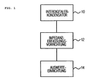
- Fig. 1 shows a schematic block diagram of a device for detecting a pad change according to an embodiment of the present invention.
- an interdigital capacitor 10 is connected to an impedance detection device for detecting impedance values of the interdigital capacitor.
- the impedance detection device is further connected to an evaluation device, which is designed to calculate an indicator quantity indicative of a temporal change of the coating using the detected impedance values.
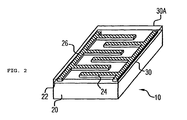
- the capacitor 10 which is preferably a planar capacitor to facilitate attachment or installation in the walls of, for example, pipelines or vessels, is disclosed in U.S. Pat Fig. 2 shown.
- the capacitor 10 can also be arranged directly on a printed circuit board.
- the capacitor 10 is formed as an interdigital capacitor in which a first comb-shaped electrode 24 and a second comb-shaped electrode 26 are arranged on a dielectric substrate 20 on a surface 22 of the dielectric substrate 20.
- the first and second comb-shaped electrodes are preferably formed in thin film technology with a pitch of several tens of ⁇ m. As it is in Fig.
- the first and second comb-shaped electrode 24 and 26 are interdigitated to each other, so that a capacitance is formed between the electrodes.
- the electrodes 24 and 26 are coated with an insulating and chemical resistant protective layer 30, which in this embodiment comprises silicon carbide (SiC).
- SiC silicon carbide
- a resistance meander (not shown) for temperature measurement can be integrated on the sensor type.
- an outer surface 30a of the protective layer 30 is used as a sensitive surface on which a coating is depositable.
- the operation of the capacitor 10 is based on the fact that the electrical impedance Z thereof is determined by the dielectric material of the substrate 22, the liquid above the sensor and the coating deposited on the layer 30. Changes, e.g. the thickness of the covering or its composition, this can be detected by measuring the impedance Z.
- the penetration depth of the electric field into the liquid essentially depends on the electrode spacing and, as a first approximation, is on the order of the electrode spacing.
- the electrode spacing can be varied by means of known technologies in the micron range, wherein the selection of the electrode spacing is made taking into account the liquid and a typical composition and thickness of a deposit deposited from the liquid.
- the size of the planar capacitor that is, more specifically, the chip on which the capacitor is applied is to be considered, that both a handling of the chip area and a corresponding dimension for a microscopic deposit formation are required.
- the size of the chip is 10 x 20 mm 2 , which surface area represents a favorable compromise between a manageable chip area and the dimensions necessary for microscopic paving.
- the capacitor has a capacitance of about 60 pF in an air environment, which value increases significantly in an aqueous environment.
- the capacitor 10 may be disposed or fixed to a wall in the working part or equipment in which a pad change is to be detected.
- the sensor chip is glued to a circuit board for installation, contacted and sealed with a liquid-tight plastic so that only the active sensor surface remains free.
- Fig. 3 shows a possible attachment, wherein the finished sensor module with the active surface almost flush in a known flange, such as the Varivent TM - flange (system component of GEA Tuschenhagen) is installed.
- a known flange such as the Varivent TM - flange (system component of GEA Tuschenhagen)
- the cables required to measure the impedance are led out to the back of an external measuring device, which may for example comprise a known impedance analyzer.
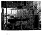
- Fig. 4 shows a picture of the experimental setup.
- a whey powder solution was used as a liquid test medium from which a deposit was to be deposited. Subsequent cleaning selected an alkaline and an acid industrial cleaner. In order to keep the consumption of liquid test medium in the laboratory low and in the interest of a forced deposit formation but worked at low flow velocities in the test track. The test stand was then designed to follow a complete life cycle of a food processing plant manually controlled. The operating cycle includes pasteurization (with deposit formation), rinsing, alkaline cleaning, rinsing again, acid cleaning and rinsing again.
- a DN25 test tube operating at a media throughput of about 200 l / h was chosen as the working part.
- the DN25 tube ensures sufficient clearance to accommodate the sensor.
- the average flow rate of 0.1 m / s, which sets at a flow rate of 200 l / h, sufficient to keep the flow turbulent, indicating the heat transfer from the pipe wall in the test medium and for realistic thermal conditions the pipe wall is important.
- the test section runs in a heat bath, which can assume considerably higher temperatures than the test medium.
- the characteristic overheating of the heat exchanger tube wall can be adjusted.
- the frequency range can also include a frequency range customary for electrochemical impedance spectroscopy, which comprises, for example, 10 Hz to 1 MHz.
- the cleaning success is determined from the recorded impedance spectra by means of a calculation method. The total number of spectra recorded during a trial is typically between 50 and 100. This ensures that sufficient data is available for the computational process.
- the sensor was removed at regular intervals in some experiments.
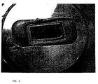
- Fig. 5 shows a condition of the sensor after it was exposed to an 8% whey powder solution at 85 ° C for a period of 120 minutes.
- a coating is formed that is not significantly different from a coating on the surfaces of the flange.
- Fig. 6 shows a representation of the arrangement of Fig. 5 after performing an alkaline and acidic cleaning cycle. As can be seen, both the metal surfaces of the mounting flange and the outer surface of the sensor after the alkaline and acid cleaning are visually completely bare.
- the alkaline cleaning step for removing organic scale constituents is very time-consuming and critical.
- a treatment time of at least 10 minutes to 20 minutes was necessary in order to achieve an overall good cleaning of the surfaces. This was confirmed in the experiments in which the time for the alkaline cleaning process had to be extended in part to over 30 minutes.
- Fig. 7 shows the sensor assembly of the experimental setup after an alkaline cleaning for 60 minutes in 2% NaOH at 60 ° C. As can be seen, both the metallic flange and the active surface of the sensor element on a mineral residue on.
- the capacitor 10 in particular due to the nature of the protective layer 30, which in this embodiment SiC, is suitable to detect a deposit change in a working part or a plant, since the deposit formation on the outer surface, ie the active Surface of the capacitor 10 is representative of the deposit formation on the metal walls of a working part.
- an impedance spectrum is taken by the impedance detection device 12 at successive time intervals, which may extend, for example, over a frequency range of 0.5 to 500 kHz.
- a change between the two last measurements is evaluated in order to obtain an indicator size indicative of a change in the pad.
- This difference method allows an end point of the cleaning with the aid of the sensor is easily detectable, since the end of the cleaning is characterized by a stationary state in which the chemical cleaning operations have come to a halt at the sensor surface and the plant surfaces.
- the measured values supplied by the sensor continuously change in large steps, whereas at the end of the cleaning the measured values fluctuate only statistically around a mean value.
- the difference method provides a simple method for detecting the end point, in which a determination is made as to whether a predetermined number of preferably consecutive indicator quantities lies within a predetermined range.
- the calculation of the indicator size can be done by a principal component analysis, which is calculated from the sensor data in a one-step or multi-step process.
- the impedance values respectively obtained during a detection are subjected to a main component transformation in order to obtain a measurement vector in a main component space from the detected impedance spectra.
- Further explanations of the principal component analysis are for example in the EP 1 143 240 A1 to find.
- the main component calculation is repeated at predetermined time intervals using, for calculation, the impedance spectra detected from the last calculation time point to the current calculation time point. Further An averaging or selection of the impedance spectra, for example by using only every other spectrum, can also be performed.
- the repeated calculation results in a trajectory of the measurement vectors in the main component space, wherein the end of the cleaning process is characterized in that the trajectory ends in a saturation point of the main component space or only fluctuates around the same statistically.
- this saturation point may be exposed to certain influences that make it difficult to apply a decision criterion for detecting a cleaning end for the trajectory in the main component space. For example, between two temporally successive cleanings with the same operating parameters, a sensitivity of the sensor may change due to sensor drifts before the start of a cleaning, so that different saturation points result for the two cleanings.
- an indicator quantity is calculated from the measurement vectors in the main component space, which allows an end of the cleaning process to be detected and a decision to intervene.
- Various criteria can be used for this purpose, for example a distance criterion or a direction criterion.
- the current measuring vector in the main component space and the preceding measuring vector in the main component space are used.
- the indicator size is also typically recalculated with each new principal component calculation, resulting in a time history of indicator sizes.
- the indicator size is used, for example by making a determination as to whether the indicator sizes are persistent, i. above a certain number, in a predetermined range. Thereafter, a cleaning end signal may be generated indicating an end of the cleaning process. Further, for example, using other detected parameters such as a time to reach the end or a detected temperature at the endpoint, a decision can be made as to whether to intervene in the cleaning process or to perform another process.
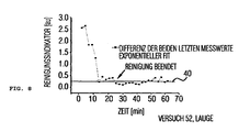
- Fig. 8 shows a sequence of indicator quantities as a function of time, which was determined during a cleaning of a pipe.
- the measured values obtained were subjected to a main component transformation at regular intervals.
- the indicator size was calculated in each case from a difference between two successive measuring vectors or sensor data sets in the main component space, the Mahalanobis distance serving as distance criterion.
- a significant advantage of the above-explained automatic detection of the end of cleaning is the use of the difference method, whereby a calibration is not necessary.
- the system is self-calibrating and can compensate for disturbances, which can occur for example by different cleaning agents or variations of the liquid food, to some extent.
Landscapes
- Chemical & Material Sciences (AREA)
- Chemical Kinetics & Catalysis (AREA)
- Electrochemistry (AREA)
- Physics & Mathematics (AREA)
- Health & Medical Sciences (AREA)
- Life Sciences & Earth Sciences (AREA)
- Analytical Chemistry (AREA)
- Biochemistry (AREA)
- General Health & Medical Sciences (AREA)
- General Physics & Mathematics (AREA)
- Immunology (AREA)
- Pathology (AREA)
- Engineering & Computer Science (AREA)
- Mechanical Engineering (AREA)
- Investigating Or Analyzing Materials By The Use Of Electric Means (AREA)
Claims (9)
- Procédé pour le réglage d'une opération de nettoyage de couches sur un outil avec un condensateur interdigital (10) avec une face extérieure (30a) sur laquelle peut se déposer une couche, de sorte qu'une impédance du condensateur interdigital (10) dépend de la couche déposée; un dispositif de détection d'impédance (12) destiné à détecter les valeurs d'impédance du condensateur interdigital (10); et un moyen d'évaluation (14) destiné à calculer une grandeur d'indicateur, qui indique une variation dans le temps de la couche, à l'aide des valeurs d'impédance détectées; le procédé présentant les étapes suivantes consistant à:détecter de manière répétée les valeurs d'impédance du condensateur interdigital (10) pendant l'opération de nettoyage;calculer une grandeur d'indicateur à l'aide des valeurs d'impédance détectées au moyen d'une analyse de composants principaux;reconnaître une fin de l'opération de nettoyage à l'aide de la grandeur d'indicateur.
- Procédé selon la revendication 1, dans lequel le condensateur interdigital présente une couche (30) présentant du SiC, une surface (30a) de la couche constituant la face extérieure.
- Procédé selon la revendication 1 ou 2, dans lequel les valeurs d'impédance comprennent un spectre d'impédance.
- Procédé selon la revendication 3, dans lequel le spectre d'impédance est détecté dans une plage de fréquences de 0,5 à 500 kHz.
- Procédé selon l'une des revendications 1 à 4, dans lequel la grandeur d'indicateur est calculée à l'aide des deux valeurs d'impédance détectées en dernier lieu.
- Procédé selon la revendication 1, dans lequel la grandeur d'indicateur est déterminée au moyen d'une comparaison entre deux vecteurs de mesure dans un espace de composants principaux.
- Procédé selon la revendication 6, dans lequel la grandeur d'indicateur est calculée au moyen d'une analyse de composants principaux dans laquelle sont utilisées toutes les valeurs d'impédance détectées, une sélection des valeurs d'impédance détectées ou les valeurs d'impédance ramenées à une moyenne.
- Procédé selon la revendication 6 ou 7, dans lequel la grandeur d'indicateur est calculée au moyen d'une comparaison entre deux vecteurs de mesure dans un espace de composants principaux.
- Procédé selon la revendication 8, dans lequel la grandeur d'indicateur est calculée au moyen d'une distance entre deux vecteurs de mesure dans l'espace de composants principaux et/ou d'une direction d'un vecteur de différence entre deux vecteurs de mesure dans l'espace de composants principaux.
Applications Claiming Priority (2)
| Application Number | Priority Date | Filing Date | Title |
|---|---|---|---|
| DE10228811 | 2002-06-27 | ||
| DE2002128811 DE10228811A1 (de) | 2002-06-27 | 2002-06-27 | Vorrichtung zum Erfassen einer Belagsänderung, Vorrichtung zum Erfassen eines Reinigungsfortschritts in einer zu reinigenden Anlage und Verfahren zum Steuern eines Reinigungsvorgangs von Belägen auf einem Arbeitsteil |
Publications (2)
| Publication Number | Publication Date |
|---|---|
| EP1376112A1 EP1376112A1 (fr) | 2004-01-02 |
| EP1376112B1 true EP1376112B1 (fr) | 2009-01-21 |
Family
ID=29716690
Family Applications (1)
| Application Number | Title | Priority Date | Filing Date |
|---|---|---|---|
| EP03014623A Expired - Lifetime EP1376112B1 (fr) | 2002-06-27 | 2003-06-26 | Procédé pour le réglage des étapes de nettoyage des couches sur un outil |
Country Status (2)
| Country | Link |
|---|---|
| EP (1) | EP1376112B1 (fr) |
| DE (2) | DE10228811A1 (fr) |
Cited By (1)
| Publication number | Priority date | Publication date | Assignee | Title |
|---|---|---|---|---|
| EP3308805A2 (fr) | 2016-10-13 | 2018-04-18 | KRONES Aktiengesellschaft | Surveillance de nettoyage au moyen des capteurs de revêtement |
Families Citing this family (6)
| Publication number | Priority date | Publication date | Assignee | Title |
|---|---|---|---|---|
| DE102012018539A1 (de) * | 2012-09-19 | 2014-03-20 | Seuffer Gmbh & Co.Kg | Verfahren und Vorrichtung zur Erfassung von Eigenschaften fluider Medien |
| DE102013001272A1 (de) * | 2013-01-24 | 2014-07-24 | Manfred Bobertag | Verfahren zur Bereitstellung eines Sensors für Eigenschaften eines Verbundmaterials, Sensor für Eigenschaften eines Verbundmaterials und Bausatz für den Einbau |
| DE102013224997A1 (de) * | 2013-12-05 | 2015-06-11 | Bayerische Motoren Werke Aktiengesellschaft | Elektromigrationsdetektion |
| DE102017115516A1 (de) * | 2017-07-11 | 2019-01-17 | Endress+Hauser SE+Co. KG | Kapazitives Füllstandsmessgerät |
| WO2019097333A1 (fr) * | 2017-11-15 | 2019-05-23 | Politecnico Di Milano | Procédé de détection et de mesure d'une couche déposée sur une surface en contact avec un milieu liquide, et capteur de détection et de mesure mettant en oeuvre ce procédé |
| DE102018131542A1 (de) * | 2018-12-10 | 2020-06-10 | Bayerische Motoren Werke Aktiengesellschaft | Reinigungszustandsermittlungsvorrichtung |
Citations (1)
| Publication number | Priority date | Publication date | Assignee | Title |
|---|---|---|---|---|
| EP1111356A2 (fr) * | 1999-12-23 | 2001-06-27 | Applied Materials, Inc. | Procédé et dispositif de traitement de substrats semiconducteurs |
Family Cites Families (13)
| Publication number | Priority date | Publication date | Assignee | Title |
|---|---|---|---|---|
| DD248504A (fr) * | ||||
| DE3431443A1 (de) * | 1984-08-27 | 1986-03-06 | INTERATOM GmbH, 5060 Bergisch Gladbach | Verfahren und vorrichtung zur frueherkennung von elektrisch leitenden niederschlaegen im inneren eines behaelters, rohrleitungssystems oder dergleichen |
| US5095278A (en) * | 1988-11-21 | 1992-03-10 | Ta Instruments, Inc. | Planar interdigitated dielectric sensor |
| US5221893A (en) * | 1990-04-09 | 1993-06-22 | Kabushiki Kaisha Toshiba | Method and device for diagnosis of paint film deterioration |
| DE4427627C2 (de) * | 1994-08-04 | 1999-03-11 | Leybold Ag | Regensensor |
| CN1191605A (zh) * | 1995-06-08 | 1998-08-26 | 环境及农业技术研究所 | 确定材料硬化程度的方法 |
| US6239601B1 (en) * | 1996-03-20 | 2001-05-29 | The United States Of America As Represented By The Administrator Of The National Aeronautics And Space Administration | Thickness measurement device for ice, or ice mixed with water or other liquid |
| US5859537A (en) * | 1996-10-03 | 1999-01-12 | Dacco Sci, Inc. | Electrochemical sensors for evaluating corrosion and adhesion on painted metal structures |
| GB9622304D0 (en) * | 1996-10-26 | 1996-12-18 | Univ Manchester | Sensor |
| DE19755418A1 (de) * | 1997-12-12 | 1999-06-24 | Fraunhofer Ges Forschung | Sensorelement und Vorrichtung zur Messung komplexer Impedanzen sowie Verwendung der Vorrichtung |
| EP1143240A1 (fr) * | 2000-02-24 | 2001-10-10 | Fraunhofer-Gesellschaft Zur Förderung Der Angewandten Forschung E.V. | Procédé et dispositif pour déterminer les caractéristiques d'un échantillon liquide comprenant plusieurs substances |
| DE10008481A1 (de) * | 2000-02-24 | 2001-09-13 | Aesculap Ag & Co Kg | Vorrichtung und Verfahren zur Bestimmung der Konsistenz von Knochenzement |
| JP2002014067A (ja) * | 2000-06-30 | 2002-01-18 | Toshiba Corp | 塗膜劣化診断方法とその装置 |
-
2002
- 2002-06-27 DE DE2002128811 patent/DE10228811A1/de not_active Withdrawn
-
2003
- 2003-06-26 EP EP03014623A patent/EP1376112B1/fr not_active Expired - Lifetime
- 2003-06-26 DE DE50311113T patent/DE50311113D1/de not_active Expired - Lifetime
Patent Citations (1)
| Publication number | Priority date | Publication date | Assignee | Title |
|---|---|---|---|---|
| EP1111356A2 (fr) * | 1999-12-23 | 2001-06-27 | Applied Materials, Inc. | Procédé et dispositif de traitement de substrats semiconducteurs |
Non-Patent Citations (1)
| Title |
|---|
| LONERGAN ET AL: "Array-based vapor sensing using chemically, carbon balck-polymer resistors", CHEM. MATER., vol. 8, 1996, pages 2298 - 2312, XP000979333 * |
Cited By (2)
| Publication number | Priority date | Publication date | Assignee | Title |
|---|---|---|---|---|
| EP3308805A2 (fr) | 2016-10-13 | 2018-04-18 | KRONES Aktiengesellschaft | Surveillance de nettoyage au moyen des capteurs de revêtement |
| DE102016219964A1 (de) | 2016-10-13 | 2018-04-19 | Krones Ag | Reinigungsüberwachung mit Belagssensoren |
Also Published As
| Publication number | Publication date |
|---|---|
| DE50311113D1 (de) | 2009-03-12 |
| EP1376112A1 (fr) | 2004-01-02 |
| DE10228811A1 (de) | 2004-01-29 |
Similar Documents
| Publication | Publication Date | Title |
|---|---|---|
| DE3904894C1 (fr) | ||
| CH661986A5 (de) | Verfahren und anordnung zum messen der verschmutzung eines kapazitiven taupunktsensors. | |
| DE102007023823B4 (de) | Thermischer Massendurchflussmesser und Verfahren zu seinem Betrieb | |
| EP4158285B1 (fr) | Capteur de flux thermique et son procédé d'exploitation | |
| DE60305744T2 (de) | Verfahren zum elektrochemischen nachweis und regelung von inorganischen schichtablagerungen | |
| DE102009000067A1 (de) | Vorrichtung zur Bestimmung und/oder Überwachung eines Massedurchflusses und Vorrichtung zur Bestimmung und/oder Überwachung einer Anlagerung einer Substanz | |
| EP0243681B1 (fr) | Procédé et dispositif pour recenser le processus de durcissement d'un système de liant inorganique aqueux | |
| DE102010030952A1 (de) | Vorrichtung zur Bestimmung und/oder Überwachung eines Volumendurchflusses und/oder eienr Durchflussgeschwindigkeit | |
| WO2008142075A1 (fr) | Procédé de diagnostic pour appareils de mesure de débit massique thermiques | |
| EP1376112A1 (fr) | Dispositif pour la détection de la modification d'une couche, dispositif pour la détection de l'état de nettoyage d'une installation et procédé pour le réglage des étapes de nettoyage des couches sur un outil | |
| DE69607693T2 (de) | Verfahren und Anordnung zum Abtasten der Qualitätsänderungen eines Harzbettes | |
| DE19627587A1 (de) | Vorrichtung zur Überwachung von Gebrauchseigenschaften von Fluiden, insbesondere von Druckflüssigkeiten in fluidtechnischen Anlagen | |
| EP0417061B1 (fr) | Procédé et dispositif pour déterminer la position véritable de fuites d'une tuyauterie guidée dans un milieu humide | |
| DE102015016742B4 (de) | Verfahren zur Überprüfung der Reagierfähigkeit eines elektrischen und/oder elektronischen Sensors | |
| DE102010018948B4 (de) | Thermischer Massendurchflussmesser mit zusätzlichen Sensormitteln sowie Verfahren zum Betrieb desselben | |
| DE69207221T2 (de) | Verfahren und Vorrichtung für quantitative in situ elektrochemische Messungen in Wasser bei hohen Temperaturen | |
| DE19723995A1 (de) | Verfahren zum Überwachen und/oder Steuern eines Granulations-, Agglomerations-, Instantisierungs-, Coating- und Trocknungsprozesses in einer Wirbelschicht oder einer bewegten Schüttung durch Bestimmung der Produktfeuchte | |
| DE202020101042U1 (de) | Korrosionsprüfgerät | |
| AT500427B1 (de) | Vorrichtung zur analyse von bestandteilen einer probe | |
| AT502876B1 (de) | Korrosionssensor | |
| EP2264445B1 (fr) | Capteur d'humidité coulométrique et procédé correspondent | |
| EP2795262B1 (fr) | Procédé pour la détection d'une précipitation de gouttelettes sur un capteur chauffé de température | |
| DE102020100722A1 (de) | Druckmessgerät mit Sensor zur Erfassung von Anhaftungen an der Messmembran sowie Verfahren zum Betreiben eines solchen Druckmessgeräts | |
| DE602004007542T2 (de) | Vorrichtung zum berührungsfreien messen der Leitfähigkeit von Wasser | |
| DE102015118232B4 (de) | System und Verfahren zum Überwachen eines Kanals, insbesondere eines MEMS-Kanals |
Legal Events
| Date | Code | Title | Description |
|---|---|---|---|
| PUAI | Public reference made under article 153(3) epc to a published international application that has entered the european phase |
Free format text: ORIGINAL CODE: 0009012 |
|
| AK | Designated contracting states |
Kind code of ref document: A1 Designated state(s): AT BE BG CH CY CZ DE DK EE ES FI FR GB GR HU IE IT LI LU MC NL PT RO SE SI SK TR |
|
| AX | Request for extension of the european patent |
Extension state: AL LT LV MK |
|
| 17P | Request for examination filed |
Effective date: 20040301 |
|
| AKX | Designation fees paid |
Designated state(s): DE FR GB IT SE |
|
| RAP1 | Party data changed (applicant data changed or rights of an application transferred) |
Owner name: FRAUNHOFER-GESELLSCHAFT ZUR FOERDERUNG DER ANGEWAN |
|
| 17Q | First examination report despatched |
Effective date: 20080128 |
|
| GRAP | Despatch of communication of intention to grant a patent |
Free format text: ORIGINAL CODE: EPIDOSNIGR1 |
|
| RTI1 | Title (correction) |
Free format text: METHOD FOR CONTROLLING A CLEANING PROGRESS OF COATINGS ON A WORKING MEMBER |
|
| GRAS | Grant fee paid |
Free format text: ORIGINAL CODE: EPIDOSNIGR3 |
|
| GRAA | (expected) grant |
Free format text: ORIGINAL CODE: 0009210 |
|
| AK | Designated contracting states |
Kind code of ref document: B1 Designated state(s): DE FR GB IT SE |
|
| REG | Reference to a national code |
Ref country code: GB Ref legal event code: FG4D Free format text: NOT ENGLISH |
|
| REF | Corresponds to: |
Ref document number: 50311113 Country of ref document: DE Date of ref document: 20090312 Kind code of ref document: P |
|
| PG25 | Lapsed in a contracting state [announced via postgrant information from national office to epo] |
Ref country code: SE Free format text: LAPSE BECAUSE OF FAILURE TO SUBMIT A TRANSLATION OF THE DESCRIPTION OR TO PAY THE FEE WITHIN THE PRESCRIBED TIME-LIMIT Effective date: 20090421 |
|
| PLBE | No opposition filed within time limit |
Free format text: ORIGINAL CODE: 0009261 |
|
| STAA | Information on the status of an ep patent application or granted ep patent |
Free format text: STATUS: NO OPPOSITION FILED WITHIN TIME LIMIT |
|
| 26N | No opposition filed |
Effective date: 20091022 |
|
| PG25 | Lapsed in a contracting state [announced via postgrant information from national office to epo] |
Ref country code: IT Free format text: LAPSE BECAUSE OF FAILURE TO SUBMIT A TRANSLATION OF THE DESCRIPTION OR TO PAY THE FEE WITHIN THE PRESCRIBED TIME-LIMIT Effective date: 20090121 |
|
| REG | Reference to a national code |
Ref country code: FR Ref legal event code: PLFP Year of fee payment: 14 |
|
| REG | Reference to a national code |
Ref country code: FR Ref legal event code: PLFP Year of fee payment: 15 |
|
| PGFP | Annual fee paid to national office [announced via postgrant information from national office to epo] |
Ref country code: FR Payment date: 20170621 Year of fee payment: 15 Ref country code: DE Payment date: 20170621 Year of fee payment: 15 Ref country code: GB Payment date: 20170626 Year of fee payment: 15 |
|
| REG | Reference to a national code |
Ref country code: DE Ref legal event code: R119 Ref document number: 50311113 Country of ref document: DE |
|
| GBPC | Gb: european patent ceased through non-payment of renewal fee |
Effective date: 20180626 |
|
| PG25 | Lapsed in a contracting state [announced via postgrant information from national office to epo] |
Ref country code: DE Free format text: LAPSE BECAUSE OF NON-PAYMENT OF DUE FEES Effective date: 20190101 Ref country code: GB Free format text: LAPSE BECAUSE OF NON-PAYMENT OF DUE FEES Effective date: 20180626 Ref country code: FR Free format text: LAPSE BECAUSE OF NON-PAYMENT OF DUE FEES Effective date: 20180630 |