EP3308805A2 - Surveillance de nettoyage au moyen des capteurs de revêtement - Google Patents
Surveillance de nettoyage au moyen des capteurs de revêtement Download PDFInfo
- Publication number
- EP3308805A2 EP3308805A2 EP17194332.7A EP17194332A EP3308805A2 EP 3308805 A2 EP3308805 A2 EP 3308805A2 EP 17194332 A EP17194332 A EP 17194332A EP 3308805 A2 EP3308805 A2 EP 3308805A2
- Authority
- EP
- European Patent Office
- Prior art keywords
- sensor
- plant
- monitoring
- process plant
- pad
- Prior art date
- Legal status (The legal status is an assumption and is not a legal conclusion. Google has not performed a legal analysis and makes no representation as to the accuracy of the status listed.)
- Granted
Links
Images

Classifications
-
- A—HUMAN NECESSITIES
- A61—MEDICAL OR VETERINARY SCIENCE; HYGIENE
- A61L—METHODS OR APPARATUS FOR STERILISING MATERIALS OR OBJECTS IN GENERAL; DISINFECTION, STERILISATION OR DEODORISATION OF AIR; CHEMICAL ASPECTS OF BANDAGES, DRESSINGS, ABSORBENT PADS OR SURGICAL ARTICLES; MATERIALS FOR BANDAGES, DRESSINGS, ABSORBENT PADS OR SURGICAL ARTICLES
- A61L2/00—Disinfection or sterilisation of materials or objects, in general; Accessories therefor
- A61L2/26—Accessories
- A61L2/28—Devices for testing the effectiveness or completeness of sterilisation or disinfection, e.g. indicators which change colour
-
- G—PHYSICS
- G01—MEASURING; TESTING
- G01D—MEASURING NOT SPECIALLY ADAPTED FOR A SPECIFIC VARIABLE; ARRANGEMENTS FOR MEASURING TWO OR MORE VARIABLES NOT COVERED IN A SINGLE OTHER SUBCLASS; TARIFF METERING APPARATUS; MEASURING OR TESTING NOT OTHERWISE PROVIDED FOR
- G01D21/00—Measuring or testing not otherwise provided for
- G01D21/02—Measuring two or more variables by means not covered by a single other subclass
-
- G—PHYSICS
- G01—MEASURING; TESTING
- G01N—INVESTIGATING OR ANALYSING MATERIALS BY DETERMINING THEIR CHEMICAL OR PHYSICAL PROPERTIES
- G01N17/00—Investigating resistance of materials to the weather, to corrosion, or to light
- G01N17/008—Monitoring fouling
-
- G—PHYSICS
- G01—MEASURING; TESTING
- G01N—INVESTIGATING OR ANALYSING MATERIALS BY DETERMINING THEIR CHEMICAL OR PHYSICAL PROPERTIES
- G01N33/00—Investigating or analysing materials by specific methods not covered by groups G01N1/00 - G01N31/00
-
- G—PHYSICS
- G01—MEASURING; TESTING
- G01N—INVESTIGATING OR ANALYSING MATERIALS BY DETERMINING THEIR CHEMICAL OR PHYSICAL PROPERTIES
- G01N33/00—Investigating or analysing materials by specific methods not covered by groups G01N1/00 - G01N31/00
- G01N33/02—Food
Definitions
- the invention relates to a system specified in the preamble of claim 1, a method specified in the preamble of claim 8 species, a sensor specified in the preamble of claim 12 species, a method specified in the preamble of claim 13 species, and a method specified in the preamble of claim 15 Art.
- capacitive sensors are used for the measurement of deposit formation.
- a disadvantage of the known sensors and methodology for determining the degree of soiling or the degree of purification of a plant or food installation is, inter alia, that the covering layer structure can only be measured for limited covering layer thicknesses and, for example, an effective production and cleaning cycle comprehensive monitoring of the hygiene state of the system is not possible is.
- a cleaning process can be understood, for example, to mean all processes or process sequences known from the prior art, in order to free a food processing system from any contamination without substantial dismantling.
- these include, for example, the so-called “cleaning in place” - or CIP- as well as the so-called “sterilization in place” or SIP method.
- CIP processes can be carried out as follows: rinsing the plant with water, cleaning the plant with an alkaline medium, e.g. at elevated temperature, rinsing the plant, cleaning the plant with an acidic cleaning agent, e.g. at elevated temperature, rinse the system with water.
- SIP sterilized
- the plant can with a sterilant such. Water with a temperature greater than 120 ° C or a chemical sterilant can be treated.
- only a basic cleaning can be sufficient. In the case of products that are particularly difficult to clean, it is also possible to clean with acid before the basic cleaning.
- a system for monitoring the hygiene state of a process plant, eg food plant, and for monitoring and controlling a cleaning process of the process plant, eg food plant may comprise at least two pad sensors for measuring deposits on parts of the process plant, eg food plant, wherein the at least two pad sensors different Measuring ranges may have. Furthermore, the at least two pad sensors should be configured to work according to different measurement principles.
- any unwanted deposits on plant parts in particular e.g. on internal plant walls (in particular, for example, inner walls of pipelines), such as, inter alia, mineral, organic and mixed organic-mineral deposits.
- Typical deposits or impurities such as mineral substances, proteins or starch, may in particular occur on parts or surfaces with an elevated temperature relative to the environment, e.g. on heat exchangers, deposit.
- the measurement of deposits may also involve the measurement of other physical properties of the coating and / or the environment of the process equipment, e.g. Food plant where the coating forms and / or a product of the process plant, e.g. Food plant, for example one through the process plant, e.g. Food plant, flowing product or cleaning medium include.
- an electrical or thermal conductivity, an electrical capacitance, a heat capacity, and / or optical absorption and / or emission properties e.g. Fluorescence properties, and / or one or more of the following properties such as flow velocity, flow rate, turbidity, color, pH, temperature, pressure or pressure loss in the system, heat transfer value of a pipe outer wall of the system, concentration of certain particles in the cleaning medium and / or in the product , Presence of volatile components;
- Product properties of the processed product such as viscosity, composition, online titration readings, transmission or reflectance measurements, responses from various online flow injection analyzes, UV adsorption readings, vibration and damping characteristics, ultrasonic measurements, wavelength-dependent light scattering, and / or optical activity (polarization angle change).
- lining sensors which can have different measuring ranges and / or which can work according to different measuring principles, can ensure a safe, more complete and continuous monitoring of the hygienic condition of the system via production and allow cleaning cycles.
- the degree of contamination of the system during production and the degree of cleaning or the Abtherapiesgrad during a cleaning process of the system can be better monitored and controlled.
- the timing at which cleaning is useful or necessary and / or the time when the cleaning can be finished can be better determined and, for example, avoided to perform unnecessary cleanings, which causes unnecessary costs and unnecessary expenditure of energy.
- the efficiency and effectiveness with which a cleaning process can be monitored can also be increased. Among other things, this can lead to minimizing downtime and minimizing the consumption of resources, such as cleaning media.
- the system may be configured such that at least one pad sensor may be configured to measure virtually unlimited pad thicknesses or configured to be able to measure thicker pad thicknesses than, for example, compared to a capacitive pad sensor.
- a pad sensor may be an ultrasonic pad sensor.
- the system may be designed so that at least one pad sensor can be a capacitive pad sensor and at least one pad sensor can be an ultrasonic pad sensor.
- At least one pad sensor can be an optical pad sensor or a thermal pad sensor or a pad sensor with conduction measurement or a pad sensor with fluorescence measurement or a pad sensor with absorption measurement.
- This type of lining sensors can also be configured to measure or configure virtually unlimited lining layer thicknesses can measure thicker or thicker coating layer thicknesses, for example, as compared to a capacitive coating sensor.
- a thermal pad sensor may be configured with a temperature sensor and at least one temperature emitter for coupling heat energy, e.g. for applying a time-varying temperature profile, to a location of the process plant to be examined, e.g. Food plant, include.
- the variety of insertable pad sensors can thereby increase the accuracy with which pad formation can be measured.
- the measuring ranges of the pad sensors can complement each other.
- the measuring ranges are different pad sensors complementary to each other, with the measuring ranges can overlap partially.
- the measuring ranges of the different pad sensors do not overlap.
- a measuring range of one pad sensor also includes the measuring range of / another.
- the measuring range of at least one lining sensor may comprise coating layer thicknesses of close to or equal to zero and / or the measuring region of at least one further lining sensor may comprise coating layer thicknesses having a maximum tolerable coating layer thickness.
- one pad sensor measuring thin pad thicknesses and another pad sensor measuring thick pad thicknesses e.g. one pad sensor measuring thin pad thicknesses and another pad sensor measuring thick pad thicknesses.
- coating layer thicknesses of 0 to 0.5 mm, and under thick coating layer thicknesses e.g. Coating layer thicknesses of 0.5 mm to 5 mm, and under a maximum tolerable coating layer thickness, e.g. Covering layer thicknesses up to 5 mm, to be understood.
- said exemplary coating layer thicknesses or covering layer thickness values may also depend on the type of lining or covering hardness, since, for example, softer coverings may be easier to remove than harder coverings, for example, softer coverings may have a larger maximum tolerable covering layer thickness than comparatively harder coverings.
- a capacitive covering sensor measures thin covering layers or thin covering layer thicknesses
- a second covering layer sensor is used by means of an ultrasonic measurement method for measuring thicker coating layers or thicker coating layer thicknesses.
- This may, for example, facilitate the determination of whether and when a cleaning of the process plant, e.g. Food plant, is necessary, for example, in a determination of the exceeding of a maximum tolerable coating layer thickness by the lining sensor whose measuring range comprises the maximum tolerable lining layer thickness.
- a lining sensor for thin lining layer thicknesses is or can be operated with a higher spatial resolution or layer thickness resolution than a lining sensor for thick lining layer thicknesses.
- This may, for example, include a more precise monitoring of the cleaning process of the process plant, e.g. Food plant, since it can be more accurately determined whether and when a reduction of the coating layer thickness by the cleaning process, the coating layer thickness is reached to zero or almost zero within a predetermined tolerance, and thus the part to be cleaned or the whole process plant, e.g. Food plant, as clean and hygienic clean.
- the process plant e.g. Food plant
- Typical resolutions for the measurement of coating layer thicknesses can be, for example, between +/- 0.5 and +/- 5 ⁇ m, depending on the type of coating and the type of lining sensor for thin coatings, and between +/- 5 and +/- 50 ⁇ m for thicker coatings.
- At least one covering sensor can also be configured to measure another / of further physical properties of the covering to be examined and / or the surroundings of the processing installation, e.g. Food plant in which the coating forms and / or a product of the process plant, e.g. Food plant.
- a pad sensor can be configured to measure a physical property of a medium flowing through the test site, in particular to be configured for measuring the electrical conductivity of a medium or fluid or fluid mixture flowing through the test site, for example by means of electrically capacitive measurement of changes in the electrical conductivity of the medium to be examined flowing through the medium.
- At least one pad sensor for example, in particular at least one pad sensor is configured to be able to measure thin coating layer thicknesses, at a difficult to clean place or at the hardest to be cleaned point of the process plant, e.g. Food plant, be appropriate.
- Exemplary locations for hard to clean sites of the process plant may e.g. High-temperature ranges of heat exchangers, pre-denaturation stages, ring boilers or central boiler of a filling device, filling valves, buffer tanks, dead spots, undercuts, pipe extensions, gaskets to materials, heated surfaces, surfaces for heat transfer or with a temperature difference include.
- At least one pad sensor for example in particular at least one pad sensor which is configured to be able to measure thicker or thicker pad layer thicknesses, even at a location with compared to other points of the process plant, e.g. Food plant, increased deposit formation, e.g. at a location with maximum deposit formation, be appropriate.
- the increased deposit formation can be caused, for example, by a temperature difference at the location which promotes deposit formation at said location in comparison to surrounding areas.
- This site with increased deposit formation may be different from a difficult-to-clean place, i. be comparatively easy to clean.
- Such an exemplary arrangement may, for example, help to ensure that the process plant, eg food plant, has been reliably hygienically cleaned, since it can be assumed, for example, that a satisfactory cleaning of a site which is difficult or most difficult to clean and / or if a satisfactory result is detected Cleaning a location of the process plant, eg food processing plant, which is particularly heavily contaminated compared to other areas of the process plant, eg food processing plant, the entire process plant, eg food processing plant, has been completely and satisfactorily cleaned.
- the at least one pad sensor can be heated.
- a location of the process plant e.g. Food plant, can be simulated, which has a relation to other parts of the system elevated temperature, and thus may be prone to increased deposit formation.
- the pad sensor does not directly to such a point of the process plant, e.g. Food plant can be attached at an elevated temperature, ensure that the formation of deposits or the hygiene state and / or cleaning history for the location of the process plant, e.g. Food plant, with elevated temperature can be monitored and regulated.
- This may, for example, improve the accuracy with which a cleaning process can be monitored, in particular because e.g. a cleaning end can be determined better and more accurately.
- the second pad sensor can have its measuring range, e.g. Covering layer thicknesses of close to or equal to zero can have a higher resolution than the covering sensor whose measuring area may include lining layer thicknesses with a predetermined maximum tolerable lining layer thickness. This can monitor the accuracy with which a cleaning process and e.g. a cleaning end can be found to increase even further.
- the at least one covering sensor whose measuring area may comprise covering layer thicknesses with a predetermined maximum tolerable covering layer thickness, and / or the optional at least one covering sensor whose measuring area comprises covering layer thicknesses of close to or equal to zero, for example a covering sensor of the type described above, thus for example a capacitive covering sensor , or an ultrasonic pad sensor, or an optical pad sensor, or a thermal pad sensor, or a coarse pad sensor, or a pad sensor with fluorescence measurement, or a pad sensor with absorbance measurement.
- the pad sensor whose lower measurement range coating layer thicknesses of near or equal to zero, and only when reaching the upper end of the measuring range of the pad sensor with lower measurement range of coating thicknesses of close to or equal to zero, the monitoring of the hygiene state at Production is switched to the lining sensor, whose measuring range covering layer thicknesses with a predetermined maximum tolerable lining layer thickness.
- the monitoring of the / a cleaning process initiated first by the / a pad sensor whose lower measurement range coating layer thicknesses with a predetermined maximum tolerable coating layer thickness includes, and only when reaching the lower end of the measuring range of the pad sensor with measuring range for coating layer thicknesses with a predetermined maximum tolerable lining layer thickness or when reaching its lower detection limit for coverings or
- the monitoring of the initiated cleaning process is switched to the / a pad sensor whose lower measurement range coating layer thicknesses of close to or equal to zero, and which may for example have a higher resolution.
- the cleaning process can be terminated at the instigation of the lining sensor or the lining sensor system.
- a signal can be output, which can signal the end of the cleaning process.
- the monitoring and / or control of the initiated cleaning process may additionally include the monitoring of rinsing, e.g. with water, a cleaning medium, wherein the monitoring of the rinsing can be done by means of a sensor which can be configured to measure a physical property of a medium flowing through the device to be cleaned, that is, for example, configured to be the electrical conductivity of a to to measure the purifying point of flowing medium.
- a sensor which can be configured to measure a physical property of a medium flowing through the device to be cleaned, that is, for example, configured to be the electrical conductivity of a to to measure the purifying point of flowing medium.
- These exemplary process steps may, as mentioned, improve hygiene safety and product safety, as well as the production downtime of the process equipment, e.g. Food plant, minimize.
- a system for monitoring the hygiene state of a process plant, e.g. Food plant, and for monitoring and controlling a cleaning process of a process plant, e.g. Food plant also include a thermal pad sensor.
- This optional exemplary thermal pad sensor may comprise at least one temperature sensor and at least one temperature emitter, and be configured for coupling heat energy into a, possibly contaminated with a pad, to be examined point of the process plant, e.g. Food plant.
- the thermal pad sensor can be configured to act on a time-variable, eg periodically variable, temperature profile in a point to be examined in the process plant, eg food plant.
- the area of the process plant to be examined for example by the temperature emitter at the site to be examined, e.g. Food plant, coupled heat energy or the applied time-varying temperature profile, can trigger a delayed change in temperature or a delayed time-varying temperature profile of the point to be examined the plant whose magnitude or amplitude and delay or phase or phase difference, for example, from the temperature sensor of the thermal lining sensor can be measured. From these measurements of magnitude or amplitude and delay (phase or phase shift or phase difference) of the temperature change (s) triggered at the site to be examined, conclusions can be drawn about the presence and the coating layer thickness of a covering.
- the temperature emitter at the site to be examined e.g. Food plant, coupled heat energy or the applied time-varying temperature profile
- This type of heat flow thermography can also contribute to a more accurate and improved monitoring of the level of contamination of the equipment during production and monitoring of the degree of cleaning or cleaning during a cleaning process of the equipment.
- a periodic temperature profile with a frequency in the range of 10 mHz to 1 Hz are applied, or with an experimentally determined frequency depending on the mechanical dimensioning of the point to be examined of the process plant, e.g. Food plant.
- the temperature profile measurement of the triggered temperature change can be carried out by a specially designed location or measuring point to be examined.
- an outer wall of the measuring point is tapered and possibly mechanically reinforced. This can simplify the measurement of the triggered temperature change without causing an impairment of the homogeneity of the measuring point.
- this can be done without affecting the homogeneity of an inner wall of the measuring point, so that the measuring point can have the same deposit behavior for coverings as the normal wall sites.
- a delay ie a phase shift of the heat conduction to the sensor, i.e. due to the presence of deposits on the site to be examined, is avoided. to the temperature sensor of the thermal lining sensor, take place, which increases with the pad thickness.
- a coating (exemplary emissivity with thermal infrared radiation ⁇ 0.9) will absorb the heat input or the heat input significantly more than the building material of the system at the point to be examined, for example bright polished stainless steel (Eg, with emissivity ⁇ 0.1), which reflects the incident heat radiation substantially away, and thus is increased by the covering compared to a piece of equipment without or with less coating, the amplitude of the measured temperature variation measurement of the triggered temperature change.
- the most difficult to clean place is usually characterized by a complex mechanical construction, such as e.g. Undercuts, transitions from gaskets to materials, surfaces for heat transfer or with a temperature difference. Their determination can result, inter alia, by empirical determination by cleaning tests, or by theoretical evaluation of the design of the plant taking into account the respective environmental or operating conditions.
- the indicator component or reference component can be used to improve the simulation of a difficult-to-clean place, e.g. To simulate a heat exchanger, or to simulate a point with increased deposit formation, also heated.
- the steps described may increase the efficiency and effectiveness of monitoring the sanitary condition of a process plant, e.g. Food plant, and the monitoring and control of a cleaning process of the process plant, e.g. Food plant, since it can be assumed, for example, that if the hard or the most difficult to clean place or the simulated hard-to-clean place clean, i. e.g. without covering, the rest of the system is clean or hygienically clean.
- the measurement of the degree of soiling or hygiene condition of the process plant, e.g. Food plant, via a measurement of the degree of contamination or hygiene state on an indicator component may also comprise a step, with deviations in the cleanability or contamination of the indicator component compared to the cleanability or soiling of the difficult-to-clean location of the process plant, e.g. Food plant, a ratio factor is determined, which is taken into account when performing a cleaning process.
- pad sensors of the type described above can be used, for example, capacitive pad sensor, or ultrasonic pad sensors, or optical pad sensors, or thermal pad sensors, or pad sensors with Kondutechnischsunk, or pad sensors with fluorescence measurement, or pad sensors with absorption measurement ,
- Said exemplary covering sensors can be integrated into the site to be examined or into the surface to be measured.
- optical measuring methods with different wavelength ranges can be used.
- at least one sight glass, or an optical opening be mounted so that observed with an evaluation unit (eg an optical unit, eg optical pad sensor) to be examined body or the indicator component can be.
- Wavelength ranges for such optical controls or measuring methods can be between 300 and 400 nm, for example in the UVA / UVB range, and / or between 400 and 700 nm in the visible range, and / or between 700 and 1000 nm in the NIR range and / or in the SWIR range between 1000 and 2500 nm.
- the optical evaluation can be carried out according to the principle of direct observation (for example by video camera), reflection (for example by means of fluorescence measurement) or by transmitted light.
- the optional indicator component may correspond to the most difficult-to-clean component and / or the location with increased deposit formation, it can be assumed that the entire system has the desired state if this component is clean.
- the means and method steps described herein are all combinable and may synergistically cooperate in monitoring the sanitary condition of a process plant, e.g. Food plant, and monitoring and controlling a cleaning process of the process plant, e.g. Food plant, to improve.
- a cleaning process of the process plant e.g. Food plant
- a cleaning of the system as needed, or adapted to the current degree of contamination of the system take place. This ensures, among other things, safe production with the lowest possible use of cleaning media.
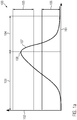
- the Fig. 1a exemplifies a possible measuring range distribution 100 of exemplary measuring ranges 105, 106 of two exemplary pad sensors, the pad sensors (not shown) can be constructed according to one of the types described above, or can work according to the various measurement principles described above.
- an exemplary trace 107 of contamination of a part of a process plant to be examined e.g. Food plant
- This course 107 can represent, for example, the course or the change in the layer thickness 102 of a covering as a function of the time 101.
- first process or time section 103 for example, the coating layer thickness change with deposit formation in a process plant, e.g. Food plant, may represent during production
- second process or time portion 104 may represent the coating layer thickness change during depletion or paving removal during cleaning.
- the covering sensors operating according to, for example, different measuring principles can have measuring ranges 105, 106 which do not overlap.
- an exemplary first measuring region 105 of a first coating sensor may comprise coating layer thicknesses with a maximum tolerable coating layer thickness 108.
- a cleaning 104 is initiated.
- the illustrated exemplary second measurement range 106 of a second coating sensor may include, for example, coating layer thicknesses of near or equal to zero.
- measuring ranges 105, 106 can also be further divided into different subregions (not shown).
- measuring range 105 may include an upper and lower measuring range.
- measuring range 106 may include an upper and lower measuring range.
- the course of the cleaning or removal of the coating can be monitored and if a satisfactory removal or adequate reduction of the coating is detected the cleaning 104 is completed and the process plant, eg food plant, go back into production operation 103.
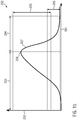
- the Fig. 1b exemplifies another possible range distribution 200 exemplary measuring ranges 205, 206 of two exemplary pad sensors, wherein the pad sensors (not shown) can be constructed again according to one of the types described above, or can work according to the different measurement principles described above.
- two different process or time sections 203, 204 shown wherein the first process or time portion 203, for example, the coating layer thickness change in deposit formation in a process plant, eg food plant, during production may represent, and the second process or time section 204 the Can show coating layer thickness change during depletion during a cleaning.
- first process or time portion 203 for example, the coating layer thickness change in deposit formation in a process plant, eg food plant, during production may represent, and the second process or time section 204 the Can show coating layer thickness change during depletion during a cleaning.
- an exemplary first measuring region 205 of a first coating sensor may in turn comprise coating layer thicknesses with a maximum tolerable coating layer thickness 208.
- a cleaning 204 may be initiated.
- the illustrated exemplary second measuring range 206 of a second coating sensor may, for example, cover coating layer thicknesses of close to or equal to zero.
- measuring ranges 205, 206 can also be analogous to 1a further divided into different sub-areas (not shown).
- measuring range 205 may include an upper and lower measuring range.
- measuring range 206 may include an upper and lower measuring range.
- the exemplary possible overlapping of the measuring regions 205, 206 may, inter alia, allow a more accurate or more complete monitoring of the hygiene state of a process plant, for example a food processing plant.
- the Fig. 2 exemplifies a possible arrangement of an exemplary thermal pad sensor 310 for a system for monitoring the hygiene state of a process plant, eg food plant, and for monitoring and controlling a cleaning process of a process plant, eg food plant, which may comprise, for example, a temperature sensor 302 and at least one temperature emitter 301 , configured for the coupling of heat energy, for example for acting on a temporally variable, eg periodically variable, temperature profile, in a point to be examined 306 of a part 304, eg a pipe wall, the process plant, eg food plant.
- a temporally variable eg periodically variable, temperature profile
- the temperature profile measurement of the temperature change triggered by the application of a time-variable temperature profile can take place at a specially designed point or measuring point 306 to be examined.
- an outer wall of the measuring point is tapered. This can simplify the measurement of the triggered temperature change, without causing an impairment of the homogeneity of the measuring point, in particular without affecting the homogeneity of an inner wall of the measuring point, so that the measuring point can have the same deposit behavior for coverings 310 as on the surrounding normal components.
- the temperature emitter 301 may be disposed opposite to the temperature sensor 302 of the exemplary thermal pad sensor 310.
- a time-varying temperature profile to a point to be examined 306 of the process plant, e.g. Food plant, by periodically heating and cooling a medium 308, e.g. Cleaning medium, done by optional heating or cooling elements 303.
- a medium 308 e.g. Cleaning medium
- Said optional heating or cooling elements 303 can be arranged in front of the point to be examined, so that, for example, the medium 308 can be subjected to a time-varying temperature profile before reaching the examination points.
- the application of the time-varying temperature profile at constant media flow 307 can take place.
- the thermal covering sensor 310 can also be operated without an (additional) temperature emitter opposite the temperature sensor 302.
- a time-varying temperature profile to a point to be examined 306 of the process plant can from a point 305, the Einstrahlstelle, opposite from the point to be examined by a medium 308, e.g. Product or cleaning medium, carried through, wherein the Einstrahlstelle can be designed, for example, so that there is a reduced deposit formation takes place or, where appropriate, by cooling the Einstrahlstelle, e.g. Peltier cooling (not shown) can be achieved.
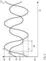
- the Fig. 3 represents exemplary heat profiles or temperature profiles 400, ie the dependence of a heat or temperature 402 on the time 401.
- profile 403 sets, for example, e.g. by the above-described means acted upon temporally variable temperature profile 403, which points to a test point of a (not shown) process equipment, e.g. Food plant, can be applied.
- Profile 403 may also be referred to as an example excitation profile.
- the exemplary variable temperature profile 403 or excitation profile is periodically variable and has an exemplary amplitude 406.
- the profile 404 represents, for example, the e.g. measured by a thermal pad sensor and triggered by the excitation profile 403 temperature change, or the e.g. measured by a thermal pad sensor and triggered by the excitation profile 403 temperature profile, at the part to be examined / the point to be examined of the process plant, e.g. Food plant, dar.
- Profile 404 may also be referred to as an exemplary measurement profile.
- the exemplary measurement profile 404 by measuring the magnitude or amplitude 407 and the delay or phase difference 405 of the measurement profile 404 compared to the excitation profile, the presence and the strength of the deposit formation or the strength of the Covering layer thickness to be closed.
- the relationship between measured amplitude 407 and measured phase difference 405 can be a function of the thermal conductivity of the coating and / or the coating thickness and / or the measurement profile 404.
- a reduction in the amplitude and greater phase shift or larger phase difference 405 can be expected.
- a larger pad thickness may decrease the amplitude 407 and increase the phase shift or phase difference 405.
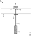
- FIG. 4 exemplifies one possible arrangement 500 of an exemplary optical pad sensor along with an exemplary indicator component 505.
- the indicator component 505 may, for example, be located at a location of the process plant which is difficult to clean, e.g. Food plant, be appropriate.
- the indicator component 505 may be located at any location 507 of the process equipment to be examined, e.g. Food installation, for example, at a location of a pipe wall 501, and wherein the indicator member 505 may be configured to a difficult to clean location of the process plant, e.g. Food plant, and / or simulate a location with increased deposit formation.
- the indicator component 505 can also be optionally heated via a heating element.
- the indicator component 505 can be heatable with a time-varying temperature profile.
- the indicator component 505 can be observed with optical measuring methods.
- an optical pad sensor 503 for example a camera, which can be arranged opposite the indicator component 505, optically detect and measure the deposit formation on the indicator component via a measuring light beam 504.
- the measuring light beam 503 may be e.g. via an optical aperture, e.g. a sight glass, mounted in / on a part of the device to be examined, which is opposite to the indicator component 505, detecting the indicator component.
- an optical aperture e.g. a sight glass
Landscapes
- Life Sciences & Earth Sciences (AREA)
- Health & Medical Sciences (AREA)
- Physics & Mathematics (AREA)
- Chemical & Material Sciences (AREA)
- General Physics & Mathematics (AREA)
- General Health & Medical Sciences (AREA)
- Pathology (AREA)
- Immunology (AREA)
- Biochemistry (AREA)
- Analytical Chemistry (AREA)
- Epidemiology (AREA)
- Public Health (AREA)
- Engineering & Computer Science (AREA)
- Biodiversity & Conservation Biology (AREA)
- Ecology (AREA)
- Environmental & Geological Engineering (AREA)
- Environmental Sciences (AREA)
- Medicinal Chemistry (AREA)
- Animal Behavior & Ethology (AREA)
- Food Science & Technology (AREA)
- Veterinary Medicine (AREA)
- Cleaning In General (AREA)
- Investigating, Analyzing Materials By Fluorescence Or Luminescence (AREA)
- Investigating Or Analyzing Materials Using Thermal Means (AREA)
- Paints Or Removers (AREA)
- Length Measuring Devices With Unspecified Measuring Means (AREA)
- Investigating Or Analyzing Materials By The Use Of Electric Means (AREA)
Applications Claiming Priority (1)
| Application Number | Priority Date | Filing Date | Title |
|---|---|---|---|
| DE102016219964.1A DE102016219964A1 (de) | 2016-10-13 | 2016-10-13 | Reinigungsüberwachung mit Belagssensoren |
Publications (3)
| Publication Number | Publication Date |
|---|---|
| EP3308805A2 true EP3308805A2 (fr) | 2018-04-18 |
| EP3308805A3 EP3308805A3 (fr) | 2018-10-10 |
| EP3308805B1 EP3308805B1 (fr) | 2024-12-11 |
Family
ID=60019726
Family Applications (1)
| Application Number | Title | Priority Date | Filing Date |
|---|---|---|---|
| EP17194332.7A Active EP3308805B1 (fr) | 2016-10-13 | 2017-10-02 | Surveillance de nettoyage au moyen des capteurs de revêtement |
Country Status (3)
| Country | Link |
|---|---|
| EP (1) | EP3308805B1 (fr) |
| CN (1) | CN107941266A (fr) |
| DE (1) | DE102016219964A1 (fr) |
Cited By (1)
| Publication number | Priority date | Publication date | Assignee | Title |
|---|---|---|---|---|
| CN112912028A (zh) * | 2018-10-29 | 2021-06-04 | 蛇牌股份公司 | 保持设备和产品监视系统 |
Families Citing this family (3)
| Publication number | Priority date | Publication date | Assignee | Title |
|---|---|---|---|---|
| DE102018131542A1 (de) * | 2018-12-10 | 2020-06-10 | Bayerische Motoren Werke Aktiengesellschaft | Reinigungszustandsermittlungsvorrichtung |
| CN111544634A (zh) * | 2020-05-20 | 2020-08-18 | 李潮云 | 一种基于数据分析的密闭环境消毒杀菌系统 |
| DE102020131124A1 (de) | 2020-11-25 | 2022-05-25 | Krones Aktiengesellschaft | Verfahren zur Überwachung und Reinigung einer Abfüllanlage, Überwachungssystem zur Überwachung von Ablagerungen in produktführenden Leitungen und Produktionsanlage |
Citations (1)
| Publication number | Priority date | Publication date | Assignee | Title |
|---|---|---|---|---|
| EP1376112B1 (fr) | 2002-06-27 | 2009-01-21 | Fraunhofer-Gesellschaft zur Förderung der angewandten Forschung e.V. | Procédé pour le réglage des étapes de nettoyage des couches sur un outil |
Family Cites Families (12)
| Publication number | Priority date | Publication date | Assignee | Title |
|---|---|---|---|---|
| NO334539B1 (no) * | 2007-10-19 | 2014-03-31 | Statoilhydro Asa | Fremgangsmåte for voksfjerning |
| WO2009135504A1 (fr) * | 2008-05-07 | 2009-11-12 | Siemens Aktiengesellschaft | Dispositif et procédé pour détecter des dépôts |
| CN101666671B (zh) * | 2008-09-05 | 2011-07-20 | 宁波柯力电气制造有限公司 | 双量程称重传感器 |
| NO332832B1 (no) * | 2009-01-30 | 2013-01-21 | Statoil Asa | Fremgangsmate for a male tykkelsen av avsetninger |
| JP5612700B2 (ja) * | 2009-12-11 | 2014-10-22 | エコラボ インコーポレイティド | ファウリング検出機構及びファウリングを検出する方法 |
| CN102169040B (zh) * | 2010-11-23 | 2012-11-14 | 中国航天科技集团公司第四研究院第四十四研究所 | 复合量程传感器跨量程测量质量质心的装置 |
| RU2452927C1 (ru) * | 2011-03-23 | 2012-06-10 | Государственное образовательное учреждение высшего профессионального образования "Сибирская государственная геодезическая академия" (ГОУВПО "СГГА") | Устройство для калибровки датчиков теплового потока |
| JP5860103B2 (ja) * | 2014-07-14 | 2016-02-16 | エコラボ インコーポレイティド | ファウリング検出機構及びファウリングを検出する方法 |
| CN104330063B (zh) * | 2014-10-22 | 2017-06-20 | 北京市东方瀚钇科技有限公司 | 一种厚度测量方法及厚度测量系统 |
| CN204286384U (zh) * | 2014-10-22 | 2015-04-22 | 北京市东方瀚钇科技有限公司 | 一种厚度测量系统 |
| RU2577389C1 (ru) * | 2015-01-27 | 2016-03-20 | Геннадий Гюсамович Громов | Способ калибровки термоэлектрических датчиков тепловых потоков |
| CN108055830B (zh) * | 2015-04-24 | 2022-01-28 | 南洋理工大学 | 用于评估反渗透系统污染状态的方法和装置 |
-
2016
- 2016-10-13 DE DE102016219964.1A patent/DE102016219964A1/de active Pending
-
2017
- 2017-10-02 EP EP17194332.7A patent/EP3308805B1/fr active Active
- 2017-10-13 CN CN201710951325.1A patent/CN107941266A/zh active Pending
Patent Citations (1)
| Publication number | Priority date | Publication date | Assignee | Title |
|---|---|---|---|---|
| EP1376112B1 (fr) | 2002-06-27 | 2009-01-21 | Fraunhofer-Gesellschaft zur Förderung der angewandten Forschung e.V. | Procédé pour le réglage des étapes de nettoyage des couches sur un outil |
Cited By (2)
| Publication number | Priority date | Publication date | Assignee | Title |
|---|---|---|---|---|
| CN112912028A (zh) * | 2018-10-29 | 2021-06-04 | 蛇牌股份公司 | 保持设备和产品监视系统 |
| CN112912028B (zh) * | 2018-10-29 | 2024-04-26 | 蛇牌股份公司 | 保持设备和产品监视系统 |
Also Published As
| Publication number | Publication date |
|---|---|
| EP3308805B1 (fr) | 2024-12-11 |
| EP3308805A3 (fr) | 2018-10-10 |
| CN107941266A (zh) | 2018-04-20 |
| DE102016219964A1 (de) | 2018-04-19 |
Similar Documents
| Publication | Publication Date | Title |
|---|---|---|
| EP3308805B1 (fr) | Surveillance de nettoyage au moyen des capteurs de revêtement | |
| EP2370804B1 (fr) | Dispositif et procédé de détection de dépôts | |
| DE102012200612A1 (de) | Reinigungsanlage für Werkstücke mit automatischer Prozessparameter-Einstellung | |
| DE69415826T2 (de) | Vorrichtung zur messung von eigenschaften einer flüssigkeit | |
| WO2008074303A2 (fr) | Capteur en ligne pour surveiller la présence d'impuretés chimiques dans des liquides hydrauliques | |
| WO1988001737A1 (fr) | Dispositif de mesure continue de la turbidite d'un liquide | |
| EP0911625B1 (fr) | Dispositif et procédé de prise d'échantillon et pour l'analyse par spectroscopie infrarouge de fluides hygroscopiques de haute pureté | |
| EP2243418A1 (fr) | Dispositif et procédé de traitement et d'analyse de canaux dans des instruments, notamment des endoscopes | |
| WO2005083386A1 (fr) | Ensemble et procede de determination spectroscopique des constituants et des concentrations de composes organiques aptes au pompage | |
| DE102015016742B4 (de) | Verfahren zur Überprüfung der Reagierfähigkeit eines elektrischen und/oder elektronischen Sensors | |
| EP2807470A1 (fr) | Sonde à réflexion | |
| DE60129563T2 (de) | Verfahren und vorrichtung zur trübungsmessung | |
| EP1044357B1 (fr) | Procede et dispositif de mise en evidence quasi-continue de la presence de constituants inorganiques ou organiques dans des fluides | |
| DE19915906C2 (de) | Korrosionsprüfvorrichtung | |
| EP3719476B1 (fr) | Conduite comprenant dispositif de mesure permettant de détecter des particules et dispositif pour la transmission de dates depuis la conduite | |
| WO2006066565A1 (fr) | Procede pour determiner la viscosite et viscosimetre correspondant | |
| WO2011035759A1 (fr) | Procédé de vérification de la réactivité d'un capteur électronique avec un produit de nettoyage dans le cadre d'une routine de test | |
| EP3717141B1 (fr) | Procédé et dispositif de mise à disposition d'un milieu par nucléation cyclique | |
| DE10341397A1 (de) | Biofouling-Online-Meßverfahren | |
| EP1775032B1 (fr) | Dispositif de nettoyage de surfaces | |
| DE102008034062B4 (de) | Verfahren und Prüfvorrichtung | |
| DE3026297C2 (fr) | ||
| DE102007016830A1 (de) | Oberflächenreinigungsvorrichtung | |
| WO1994016288A1 (fr) | Procede et dispositif pour la mesure de l'epaisseur d'un gateau de filtre | |
| AT16662U1 (de) | Vorrichtung zum Reinigen von Sensoren |
Legal Events
| Date | Code | Title | Description |
|---|---|---|---|
| PUAI | Public reference made under article 153(3) epc to a published international application that has entered the european phase |
Free format text: ORIGINAL CODE: 0009012 |
|
| STAA | Information on the status of an ep patent application or granted ep patent |
Free format text: STATUS: THE APPLICATION HAS BEEN PUBLISHED |
|
| AK | Designated contracting states |
Kind code of ref document: A2 Designated state(s): AL AT BE BG CH CY CZ DE DK EE ES FI FR GB GR HR HU IE IS IT LI LT LU LV MC MK MT NL NO PL PT RO RS SE SI SK SM TR |
|
| AX | Request for extension of the european patent |
Extension state: BA ME |
|
| RIC1 | Information provided on ipc code assigned before grant |
Ipc: G01N 27/00 20060101ALI20180508BHEP Ipc: A61L 2/24 20060101ALI20180508BHEP Ipc: G01N 17/00 20060101ALI20180508BHEP Ipc: A61L 2/28 20060101ALI20180508BHEP Ipc: A61L 2/18 20060101AFI20180508BHEP |
|
| PUAL | Search report despatched |
Free format text: ORIGINAL CODE: 0009013 |
|
| AK | Designated contracting states |
Kind code of ref document: A3 Designated state(s): AL AT BE BG CH CY CZ DE DK EE ES FI FR GB GR HR HU IE IS IT LI LT LU LV MC MK MT NL NO PL PT RO RS SE SI SK SM TR |
|
| AX | Request for extension of the european patent |
Extension state: BA ME |
|
| RIC1 | Information provided on ipc code assigned before grant |
Ipc: G01N 27/00 20060101ALI20180906BHEP Ipc: A61L 2/24 20060101ALI20180906BHEP Ipc: A61L 2/18 20060101AFI20180906BHEP Ipc: G01N 17/00 20060101ALI20180906BHEP Ipc: A61L 2/28 20060101ALI20180906BHEP |
|
| STAA | Information on the status of an ep patent application or granted ep patent |
Free format text: STATUS: REQUEST FOR EXAMINATION WAS MADE |
|
| 17P | Request for examination filed |
Effective date: 20190410 |
|
| RBV | Designated contracting states (corrected) |
Designated state(s): AL AT BE BG CH CY CZ DE DK EE ES FI FR GB GR HR HU IE IS IT LI LT LU LV MC MK MT NL NO PL PT RO RS SE SI SK SM TR |
|
| STAA | Information on the status of an ep patent application or granted ep patent |
Free format text: STATUS: EXAMINATION IS IN PROGRESS |
|
| 17Q | First examination report despatched |
Effective date: 20220316 |
|
| P01 | Opt-out of the competence of the unified patent court (upc) registered |
Effective date: 20230523 |
|
| GRAP | Despatch of communication of intention to grant a patent |
Free format text: ORIGINAL CODE: EPIDOSNIGR1 |
|
| STAA | Information on the status of an ep patent application or granted ep patent |
Free format text: STATUS: GRANT OF PATENT IS INTENDED |
|
| INTG | Intention to grant announced |
Effective date: 20240725 |
|
| GRAS | Grant fee paid |
Free format text: ORIGINAL CODE: EPIDOSNIGR3 |
|
| GRAA | (expected) grant |
Free format text: ORIGINAL CODE: 0009210 |
|
| STAA | Information on the status of an ep patent application or granted ep patent |
Free format text: STATUS: THE PATENT HAS BEEN GRANTED |
|
| AK | Designated contracting states |
Kind code of ref document: B1 Designated state(s): AL AT BE BG CH CY CZ DE DK EE ES FI FR GB GR HR HU IE IS IT LI LT LU LV MC MK MT NL NO PL PT RO RS SE SI SK SM TR |
|
| REG | Reference to a national code |
Ref country code: GB Ref legal event code: FG4D Free format text: NOT ENGLISH |
|
| REG | Reference to a national code |
Ref country code: CH Ref legal event code: EP |
|
| REG | Reference to a national code |
Ref country code: IE Ref legal event code: FG4D Free format text: LANGUAGE OF EP DOCUMENT: GERMAN |
|
| REG | Reference to a national code |
Ref country code: DE Ref legal event code: R096 Ref document number: 502017016603 Country of ref document: DE |
|
| REG | Reference to a national code |
Ref country code: LT Ref legal event code: MG9D |
|
| PG25 | Lapsed in a contracting state [announced via postgrant information from national office to epo] |
Ref country code: HR Free format text: LAPSE BECAUSE OF FAILURE TO SUBMIT A TRANSLATION OF THE DESCRIPTION OR TO PAY THE FEE WITHIN THE PRESCRIBED TIME-LIMIT Effective date: 20241211 |
|
| PG25 | Lapsed in a contracting state [announced via postgrant information from national office to epo] |
Ref country code: FI Free format text: LAPSE BECAUSE OF FAILURE TO SUBMIT A TRANSLATION OF THE DESCRIPTION OR TO PAY THE FEE WITHIN THE PRESCRIBED TIME-LIMIT Effective date: 20241211 |
|
| PG25 | Lapsed in a contracting state [announced via postgrant information from national office to epo] |
Ref country code: BG Free format text: LAPSE BECAUSE OF FAILURE TO SUBMIT A TRANSLATION OF THE DESCRIPTION OR TO PAY THE FEE WITHIN THE PRESCRIBED TIME-LIMIT Effective date: 20241211 |
|
| REG | Reference to a national code |
Ref country code: NL Ref legal event code: MP Effective date: 20241211 |
|
| PG25 | Lapsed in a contracting state [announced via postgrant information from national office to epo] |
Ref country code: ES Free format text: LAPSE BECAUSE OF FAILURE TO SUBMIT A TRANSLATION OF THE DESCRIPTION OR TO PAY THE FEE WITHIN THE PRESCRIBED TIME-LIMIT Effective date: 20241211 |
|
| PG25 | Lapsed in a contracting state [announced via postgrant information from national office to epo] |
Ref country code: NO Free format text: LAPSE BECAUSE OF FAILURE TO SUBMIT A TRANSLATION OF THE DESCRIPTION OR TO PAY THE FEE WITHIN THE PRESCRIBED TIME-LIMIT Effective date: 20250311 |
|
| PG25 | Lapsed in a contracting state [announced via postgrant information from national office to epo] |
Ref country code: LV Free format text: LAPSE BECAUSE OF FAILURE TO SUBMIT A TRANSLATION OF THE DESCRIPTION OR TO PAY THE FEE WITHIN THE PRESCRIBED TIME-LIMIT Effective date: 20241211 Ref country code: GR Free format text: LAPSE BECAUSE OF FAILURE TO SUBMIT A TRANSLATION OF THE DESCRIPTION OR TO PAY THE FEE WITHIN THE PRESCRIBED TIME-LIMIT Effective date: 20250312 |
|
| PG25 | Lapsed in a contracting state [announced via postgrant information from national office to epo] |
Ref country code: RS Free format text: LAPSE BECAUSE OF FAILURE TO SUBMIT A TRANSLATION OF THE DESCRIPTION OR TO PAY THE FEE WITHIN THE PRESCRIBED TIME-LIMIT Effective date: 20250311 |
|
| PG25 | Lapsed in a contracting state [announced via postgrant information from national office to epo] |
Ref country code: NL Free format text: LAPSE BECAUSE OF FAILURE TO SUBMIT A TRANSLATION OF THE DESCRIPTION OR TO PAY THE FEE WITHIN THE PRESCRIBED TIME-LIMIT Effective date: 20241211 |
|
| PG25 | Lapsed in a contracting state [announced via postgrant information from national office to epo] |
Ref country code: SM Free format text: LAPSE BECAUSE OF FAILURE TO SUBMIT A TRANSLATION OF THE DESCRIPTION OR TO PAY THE FEE WITHIN THE PRESCRIBED TIME-LIMIT Effective date: 20241211 |
|
| PG25 | Lapsed in a contracting state [announced via postgrant information from national office to epo] |
Ref country code: PL Free format text: LAPSE BECAUSE OF FAILURE TO SUBMIT A TRANSLATION OF THE DESCRIPTION OR TO PAY THE FEE WITHIN THE PRESCRIBED TIME-LIMIT Effective date: 20241211 |
|
| PG25 | Lapsed in a contracting state [announced via postgrant information from national office to epo] |
Ref country code: IS Free format text: LAPSE BECAUSE OF FAILURE TO SUBMIT A TRANSLATION OF THE DESCRIPTION OR TO PAY THE FEE WITHIN THE PRESCRIBED TIME-LIMIT Effective date: 20250411 |
|
| PG25 | Lapsed in a contracting state [announced via postgrant information from national office to epo] |
Ref country code: PT Free format text: LAPSE BECAUSE OF FAILURE TO SUBMIT A TRANSLATION OF THE DESCRIPTION OR TO PAY THE FEE WITHIN THE PRESCRIBED TIME-LIMIT Effective date: 20250411 |
|
| PG25 | Lapsed in a contracting state [announced via postgrant information from national office to epo] |
Ref country code: EE Free format text: LAPSE BECAUSE OF FAILURE TO SUBMIT A TRANSLATION OF THE DESCRIPTION OR TO PAY THE FEE WITHIN THE PRESCRIBED TIME-LIMIT Effective date: 20241211 |
|
| PG25 | Lapsed in a contracting state [announced via postgrant information from national office to epo] |
Ref country code: RO Free format text: LAPSE BECAUSE OF FAILURE TO SUBMIT A TRANSLATION OF THE DESCRIPTION OR TO PAY THE FEE WITHIN THE PRESCRIBED TIME-LIMIT Effective date: 20241211 |
|
| PG25 | Lapsed in a contracting state [announced via postgrant information from national office to epo] |
Ref country code: SK Free format text: LAPSE BECAUSE OF FAILURE TO SUBMIT A TRANSLATION OF THE DESCRIPTION OR TO PAY THE FEE WITHIN THE PRESCRIBED TIME-LIMIT Effective date: 20241211 |
|
| PG25 | Lapsed in a contracting state [announced via postgrant information from national office to epo] |
Ref country code: CZ Free format text: LAPSE BECAUSE OF FAILURE TO SUBMIT A TRANSLATION OF THE DESCRIPTION OR TO PAY THE FEE WITHIN THE PRESCRIBED TIME-LIMIT Effective date: 20241211 |
|
| PG25 | Lapsed in a contracting state [announced via postgrant information from national office to epo] |
Ref country code: IT Free format text: LAPSE BECAUSE OF FAILURE TO SUBMIT A TRANSLATION OF THE DESCRIPTION OR TO PAY THE FEE WITHIN THE PRESCRIBED TIME-LIMIT Effective date: 20241211 |
|
| PG25 | Lapsed in a contracting state [announced via postgrant information from national office to epo] |
Ref country code: SE Free format text: LAPSE BECAUSE OF FAILURE TO SUBMIT A TRANSLATION OF THE DESCRIPTION OR TO PAY THE FEE WITHIN THE PRESCRIBED TIME-LIMIT Effective date: 20241211 |
|
| REG | Reference to a national code |
Ref country code: DE Ref legal event code: R097 Ref document number: 502017016603 Country of ref document: DE |
|
| PG25 | Lapsed in a contracting state [announced via postgrant information from national office to epo] |
Ref country code: DK Free format text: LAPSE BECAUSE OF FAILURE TO SUBMIT A TRANSLATION OF THE DESCRIPTION OR TO PAY THE FEE WITHIN THE PRESCRIBED TIME-LIMIT Effective date: 20241211 |
|
| PLBE | No opposition filed within time limit |
Free format text: ORIGINAL CODE: 0009261 |
|
| STAA | Information on the status of an ep patent application or granted ep patent |
Free format text: STATUS: NO OPPOSITION FILED WITHIN TIME LIMIT |
|
| REG | Reference to a national code |
Ref country code: CH Ref legal event code: L10 Free format text: ST27 STATUS EVENT CODE: U-0-0-L10-L00 (AS PROVIDED BY THE NATIONAL OFFICE) Effective date: 20251022 |
|
| 26N | No opposition filed |
Effective date: 20250912 |
|
| PGFP | Annual fee paid to national office [announced via postgrant information from national office to epo] |
Ref country code: DE Payment date: 20250902 Year of fee payment: 9 |
|
| REG | Reference to a national code |
Ref country code: CH Ref legal event code: H13 Free format text: ST27 STATUS EVENT CODE: U-0-0-H10-H13 (AS PROVIDED BY THE NATIONAL OFFICE) Effective date: 20260527 |
|
| PG25 | Lapsed in a contracting state [announced via postgrant information from national office to epo] |
Ref country code: LU Free format text: LAPSE BECAUSE OF NON-PAYMENT OF DUE FEES Effective date: 20251002 |
|
| REG | Reference to a national code |
Ref country code: BE Ref legal event code: MM Effective date: 20251031 |
|
| GBPC | Gb: european patent ceased through non-payment of renewal fee |
Effective date: 20251002 |
|
| PG25 | Lapsed in a contracting state [announced via postgrant information from national office to epo] |
Ref country code: LT Free format text: LAPSE BECAUSE OF FAILURE TO SUBMIT A TRANSLATION OF THE DESCRIPTION OR TO PAY THE FEE WITHIN THE PRESCRIBED TIME-LIMIT Effective date: 20241211 |
|
| PG25 | Lapsed in a contracting state [announced via postgrant information from national office to epo] |
Ref country code: MC Free format text: LAPSE BECAUSE OF FAILURE TO SUBMIT A TRANSLATION OF THE DESCRIPTION OR TO PAY THE FEE WITHIN THE PRESCRIBED TIME-LIMIT Effective date: 20241211 |
|
| PG25 | Lapsed in a contracting state [announced via postgrant information from national office to epo] |
Ref country code: GB Free format text: LAPSE BECAUSE OF NON-PAYMENT OF DUE FEES Effective date: 20251002 |
|
| PG25 | Lapsed in a contracting state [announced via postgrant information from national office to epo] |
Ref country code: CH Free format text: LAPSE BECAUSE OF NON-PAYMENT OF DUE FEES Effective date: 20251031 Ref country code: BE Free format text: LAPSE BECAUSE OF NON-PAYMENT OF DUE FEES Effective date: 20251031 |
|
| PG25 | Lapsed in a contracting state [announced via postgrant information from national office to epo] |
Ref country code: FR Free format text: LAPSE BECAUSE OF NON-PAYMENT OF DUE FEES Effective date: 20251031 |