EP1376282A2 - Système de contrôle avec surveillance d'actionneur - Google Patents
Système de contrôle avec surveillance d'actionneur Download PDFInfo
- Publication number
- EP1376282A2 EP1376282A2 EP03013752A EP03013752A EP1376282A2 EP 1376282 A2 EP1376282 A2 EP 1376282A2 EP 03013752 A EP03013752 A EP 03013752A EP 03013752 A EP03013752 A EP 03013752A EP 1376282 A2 EP1376282 A2 EP 1376282A2
- Authority
- EP
- European Patent Office
- Prior art keywords
- actuator
- processor
- unit
- parameter values
- control system
- Prior art date
- Legal status (The legal status is an assumption and is not a legal conclusion. Google has not performed a legal analysis and makes no representation as to the accuracy of the status listed.)
- Withdrawn
Links
Images
Classifications
-
- G—PHYSICS
- G05—CONTROLLING; REGULATING
- G05B—CONTROL OR REGULATING SYSTEMS IN GENERAL; FUNCTIONAL ELEMENTS OF SUCH SYSTEMS; MONITORING OR TESTING ARRANGEMENTS FOR SUCH SYSTEMS OR ELEMENTS
- G05B19/00—Program-control systems
- G05B19/02—Program-control systems electric
- G05B19/04—Program control other than numerical control, i.e. in sequence controllers or logic controllers
- G05B19/042—Program control other than numerical control, i.e. in sequence controllers or logic controllers using digital processors
- G05B19/0428—Safety, monitoring
-
- G—PHYSICS
- G05—CONTROLLING; REGULATING
- G05B—CONTROL OR REGULATING SYSTEMS IN GENERAL; FUNCTIONAL ELEMENTS OF SUCH SYSTEMS; MONITORING OR TESTING ARRANGEMENTS FOR SUCH SYSTEMS OR ELEMENTS
- G05B19/00—Program-control systems
- G05B19/02—Program-control systems electric
- G05B19/04—Program control other than numerical control, i.e. in sequence controllers or logic controllers
- G05B19/05—Programmable logic controllers, e.g. simulating logic interconnections of signals according to ladder diagrams or function charts
- G05B19/058—Safety, monitoring
-
- G—PHYSICS
- G05—CONTROLLING; REGULATING
- G05B—CONTROL OR REGULATING SYSTEMS IN GENERAL; FUNCTIONAL ELEMENTS OF SUCH SYSTEMS; MONITORING OR TESTING ARRANGEMENTS FOR SUCH SYSTEMS OR ELEMENTS
- G05B2219/00—Program-control systems
- G05B2219/10—Plc systems
- G05B2219/14—Plc safety
- G05B2219/14055—Make log, journal, history file of state changes
-
- G—PHYSICS
- G05—CONTROLLING; REGULATING
- G05B—CONTROL OR REGULATING SYSTEMS IN GENERAL; FUNCTIONAL ELEMENTS OF SUCH SYSTEMS; MONITORING OR TESTING ARRANGEMENTS FOR SUCH SYSTEMS OR ELEMENTS
- G05B2219/00—Program-control systems
- G05B2219/20—Pc systems
- G05B2219/24—Pc safety
- G05B2219/24042—Signature analysis, compare recorded with current data, if error then alarm
-
- G—PHYSICS
- G05—CONTROLLING; REGULATING
- G05B—CONTROL OR REGULATING SYSTEMS IN GENERAL; FUNCTIONAL ELEMENTS OF SUCH SYSTEMS; MONITORING OR TESTING ARRANGEMENTS FOR SUCH SYSTEMS OR ELEMENTS
- G05B2219/00—Program-control systems
- G05B2219/20—Pc systems
- G05B2219/24—Pc safety
- G05B2219/24055—Trace, store a working, operation history
-
- G—PHYSICS
- G05—CONTROLLING; REGULATING
- G05B—CONTROL OR REGULATING SYSTEMS IN GENERAL; FUNCTIONAL ELEMENTS OF SUCH SYSTEMS; MONITORING OR TESTING ARRANGEMENTS FOR SUCH SYSTEMS OR ELEMENTS
- G05B2219/00—Program-control systems
- G05B2219/20—Pc systems
- G05B2219/24—Pc safety
- G05B2219/24077—Module detects wear, changes of controlled device, statistical evaluation
-
- G—PHYSICS
- G05—CONTROLLING; REGULATING
- G05B—CONTROL OR REGULATING SYSTEMS IN GENERAL; FUNCTIONAL ELEMENTS OF SUCH SYSTEMS; MONITORING OR TESTING ARRANGEMENTS FOR SUCH SYSTEMS OR ELEMENTS
- G05B2219/00—Program-control systems
- G05B2219/20—Pc systems
- G05B2219/25—Pc structure of the system
- G05B2219/25423—Verification of controlled value by comparing with recorded value, signature
Definitions
- the invention relates to a control system with a Central unit and at least one actuator control unit, between the central unit of the control system and at least an actuator to be controlled is connected, the Actuator control unit a control switch for controlling the Actuator includes.
- the invention further relates to a Actuator control unit and a method for generating a wear-dependent signal of an actuator.
- actuators used to, for example, high currents or voltages to switch. But non-electrical quantities, for example pressure, can be controlled via a valve.
- the actuator is switched on or off via a control switch switched off. This control switch is by means of a switched low voltage.
- actuators are, for example Contactors or valves known. These are, for example in programmable logic controllers for control of processes used.
- DE 197 23 563 describes a method for function monitoring an electromagnetic actuator with at least described an electromagnet that is on one against the Force at least one return spring movable armature Actuation of an actuator acts, especially one electromagnetic actuator for actuating a gas exchange valve on a cylinder of a piston internal combustion engine, where the electrical power of the magnet is about an electrical control is controlled and in which the each of the controlled electrical performance parameters dependent other electrical performance parameters than monitoring parameters over time as the actual value is recorded and with the for proper functioning in the control over time of the monitoring parameter compared as a target value and at a Deviation an actuating signal is generated.
- the disadvantage of this implementation is that it is complex to adapt the electrical control to the respective switching characteristic of the actuator.
- the invention is based on the idea that actuators in the Have an almost ideal switching characteristic when new. This changes due to frequent switching or wear Switching characteristic.
- the invention therefore provides for monitoring and to arrange storage means, which the switching characteristic of the actuator in new condition and after one definable number of switching operations the current switching characteristic record and with the stored switching characteristic in Compare new condition.
- Actuators are operated via control switches.
- a central unit controls an actuator control unit, which for Control of the actuator is provided.
- This actuator control unit includes a control switch that is dependent of the control signals supplied to the actuator off.
- the actuator control unit further comprises one Processor for controlling communication between one Central unit and actuator control unit and for control of the switching process of the control switch and a monitoring unit for recording switch-specific parameter values. From the switch-specific parameter values a switching characteristic over the time of the switching process.
- This monitoring unit includes Devices for measuring switch-specific parameters, especially of current and / or voltage values above the time of switching.
- the measurement results recorded by the monitoring unit fed to the processor as actual parameter values.
- the processor becomes dependent on a comparison of actual parameter values generates a signal with stored reference parameter values, which is provided for feeding to the control unit.
- the actuator control unit is advantageously a storage device for storing reference parameter values arranged.
- the switch-specific parameters from the monitoring unit recorded and transmitted to the processor and there as reference parameter values saved.
- the time can also be from one Users can be set.
- an actuator is only replaced if due to Deviations between reference parameter values and actual parameter values a signal is generated which is a deviation displays. This eliminates the need for regular checking of all actuators. This means that actuators can also operate well beyond one the previously specified switching frequency can also be operated. Early total failures, on the other hand, are immediately immediately recognized.
- the task is also performed by an actuator control unit Triggering of an actuator with a control switch solved, in which a processor for controlling the communication and the Switching sequence of the control switch and a monitoring unit for recording switch-specific parameter values are arranged, the monitoring unit with the Processor is coupled and dependent in the processor a comparison of actual parameter values with saved ones Reference signal values a signal can be generated.
- the task is also accomplished by a method of generating a wear-dependent signal of an actuator solved, in which the current and / or voltage values during a switching operation a control switch of the actuator over time and the current and / or voltage values in one processor arranged for the actuator control unit for processing are supplied and this current and / or in the processor Voltage values with reference current and / or reference voltage values be compared and depending on one Comparison a signal is generated, which is via a bus coupling is directed to a central control unit.
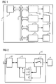
- a control system 1 is shown in FIG. This can be implemented, for example, by a programmable logic controller (PLC).
- PLC programmable logic controller
- a central unit 2 is connected to the actuator control units E 1 - E 4 via a bus system 3.
- the actuator control units E 1 - E 4 switch the actuators A 1 - A 4 on or off.
- FIG. 2 shows the structure of an actuator control unit E with a control switch 12, a monitoring unit 11 and a processor 10. Furthermore, an actuator A is shown, which is switched on or off by this actuator control unit E. becomes. A standardized is implemented via a bus coupling unit 13 Interface for coupling to bus systems 3 enables.
- the processor 10 is advantageously by a signal processor realized the communication with the parent Central unit 2 of the PLC and also the switching processes of the control switch 12 controls. Because both solenoid valves as well as Sagittarius because of their very different Design no generalizable switching characteristics have a "teach in” before the actual evaluation or learning cycle required. To do this, turn on or controlled by user commands via several regular ones Switching processes Switching characteristics recorded and saved. Out the resulting family of curves becomes in the simplest case by averaging the typical for this actuator Reference characteristic curve determined and saved.
- the switching characteristics show, for example, when switching on of an inductive actuator has an e-function of the current. If the characteristic curve is flatter than the stored reference characteristic curve, can, for example, of a gradual increase of contact resistance are assumed. Is she against it steeper, this indicates a difficult anchor, maybe due to corrosion. In both cases there is an Checking the actuator also makes sense if it is apparently still malfunction-free.
- Control system Due to the learning phase for the reference characteristics is a Control system according to the invention is also capable of actuator types monitor that have no inductive loads. It can also be used for purely ohmic or motor or capacitive loads are used.
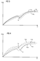
- FIG. 3 shows a typical current characteristic curve K R , such as occurs when a valve is switched on, for example.
- the tolerance limits K RO and K RU are also shown, within which a correct switching valve can be assumed. If the measured actual parameter values, in this case the current values, are outside the tolerance range, there is probably a fault.
- the switching time of the armature is denoted by t A.
- FIG. 4 shows two abnormal switching processes, error characteristic curve K ws shows the beginning of a turn short and error characteristic curve K SA shows an armature that is difficult to move .
- the detected parameter values are at least partially outside the tolerance range K RO and K RU , which gives a sufficiently high probability that the actuator will fail in the near future.
Landscapes
- Physics & Mathematics (AREA)
- General Physics & Mathematics (AREA)
- Engineering & Computer Science (AREA)
- Automation & Control Theory (AREA)
- Testing And Monitoring For Control Systems (AREA)
- Safety Devices In Control Systems (AREA)
- Programmable Controllers (AREA)
Applications Claiming Priority (2)
| Application Number | Priority Date | Filing Date | Title |
|---|---|---|---|
| DE2002126977 DE10226977A1 (de) | 2002-06-17 | 2002-06-17 | Steuersystem mit Aktuatorüberwachung |
| DE10226977 | 2002-06-17 |
Publications (2)
| Publication Number | Publication Date |
|---|---|
| EP1376282A2 true EP1376282A2 (fr) | 2004-01-02 |
| EP1376282A3 EP1376282A3 (fr) | 2005-01-19 |
Family
ID=29594588
Family Applications (1)
| Application Number | Title | Priority Date | Filing Date |
|---|---|---|---|
| EP03013752A Withdrawn EP1376282A3 (fr) | 2002-06-17 | 2003-06-17 | Système de contrôle avec surveillance d'actionneur |
Country Status (2)
| Country | Link |
|---|---|
| EP (1) | EP1376282A3 (fr) |
| DE (1) | DE10226977A1 (fr) |
Cited By (1)
| Publication number | Priority date | Publication date | Assignee | Title |
|---|---|---|---|---|
| WO2008128495A1 (fr) | 2007-04-24 | 2008-10-30 | Thomas Magnete Gmbh | Système et procédé pour appeler des données caractéristiques |
Families Citing this family (1)
| Publication number | Priority date | Publication date | Assignee | Title |
|---|---|---|---|---|
| DE102018221270A1 (de) * | 2018-12-07 | 2020-06-10 | Phoenix Contact Gmbh & Co. Kg | Vorrichtung und Verfahren zur Verschleißerkennung einer elektromechanischen Schalteinrichtung |
Family Cites Families (2)
| Publication number | Priority date | Publication date | Assignee | Title |
|---|---|---|---|---|
| US5771174A (en) * | 1995-12-21 | 1998-06-23 | Measurex Corporation | Distributed intelligence actuator controller with peer-to-peer actuator communication |
| DE19605722C2 (de) * | 1996-02-16 | 1998-07-09 | Mannesmann Sachs Ag | Einrichtung zur Funktionsüberprüfung einer elektrisch steuerbaren Aktuatoranordnung |
-
2002
- 2002-06-17 DE DE2002126977 patent/DE10226977A1/de not_active Withdrawn
-
2003
- 2003-06-17 EP EP03013752A patent/EP1376282A3/fr not_active Withdrawn
Cited By (2)
| Publication number | Priority date | Publication date | Assignee | Title |
|---|---|---|---|---|
| WO2008128495A1 (fr) | 2007-04-24 | 2008-10-30 | Thomas Magnete Gmbh | Système et procédé pour appeler des données caractéristiques |
| EP2142967A1 (fr) * | 2007-04-24 | 2010-01-13 | THOMAS MAGNETE GmbH | Système et procédé pour appeler des données caractéristiques |
Also Published As
| Publication number | Publication date |
|---|---|
| EP1376282A3 (fr) | 2005-01-19 |
| DE10226977A1 (de) | 2003-12-24 |
Similar Documents
| Publication | Publication Date | Title |
|---|---|---|
| DE102016124083B4 (de) | Verfahren zur Überwachung einer elektromechanischen Komponente eines Automatisierungssystems | |
| EP0676055B1 (fr) | Agencement de circuits permettant de surveiller une pluralite de bobines | |
| EP4330694B1 (fr) | Dispositif et procédé permettant de détecter de l'usure dans un appareil électromécanique | |
| EP2357484B1 (fr) | Procédé de diagnostic d'une connexion électrique et unité de sortie | |
| WO2022218553A1 (fr) | Procédé de détection d'une défaillance dans un relais | |
| DE102021111192A1 (de) | Vorrichtung und Verfahren zum Erkennen einer Abnutzung einer elektromechanischen Einrichtung | |
| WO2019086205A1 (fr) | Dispositif de surveillance de sécurité destiné à surveiller des états relatifs à la sécurité dans une installation de transport de personnes ainsi que procédé destiné à faire fonctionner ce dernier | |
| EP0338374A2 (fr) | Procédé et dispositif de commande d'une installation d'actionnement d'un disjoncteur de moyenne ou haute tension | |
| EP2546852B1 (fr) | Relais de sécurité bistable | |
| EP2434358B1 (fr) | Procédé de fonctionnement d'un système redondant et système | |
| EP3465898B1 (fr) | Démarreur progressif, procédé de fonctionnement et système de commutation | |
| DE112019005910T5 (de) | Steuervorrichtung einer elektromagnetischenbremse und steuervorrichtung | |
| EP1376282A2 (fr) | Système de contrôle avec surveillance d'actionneur | |
| EP3977496B1 (fr) | Procédé de prédiction de défaillance d'un relais élémentaire | |
| EP1993879B1 (fr) | Procédé et dispositif de commande d'un agencement de circuit au moyen d'actionneurs électriques | |
| DE102010021640A1 (de) | Verfahren und Vorrichtung zur Ansteuerung einer Armatur | |
| DE102018218799B4 (de) | Aktoreinrichtung, Ventileinrichtung und Verfahren zur Erfassung einer Stellung eines Stellglieds | |
| EP1314071A2 (fr) | Procede et dispositif pour surveiller une machine | |
| DE102005053405B4 (de) | Verfahren und Vorrichtung zur Überwachung eines Kraftstoffzumesssystems | |
| BE1030869B1 (de) | Verfahren zur Ansteuerung eines elektromechanischen Schaltelements | |
| DE102020122147B4 (de) | Elektrohydraulische steuereinheit mit notbetrieb und umschalt- und diagnoseeinheit für ausfallsicheren betrieb | |
| EP4372236A1 (fr) | Détection de mouvement de commandes électroniques | |
| WO2023241974A1 (fr) | Dispositif de surveillance pour une électrovanne d'un système à air comprimé de véhicule, système composé de l'électrovanne, du dispositif de surveillance et d'un dispositif de commande, et procédé de surveillance de l'électrovanne | |
| DE102020210339B4 (de) | Schaltungsanordnung und Verfahren zur Fehlererkennung | |
| DE102018219580A1 (de) | Verfahren und Vorrichtung zur Diagnose bei einem Ventil mit elektromagnetischer Betätigung |
Legal Events
| Date | Code | Title | Description |
|---|---|---|---|
| PUAI | Public reference made under article 153(3) epc to a published international application that has entered the european phase |
Free format text: ORIGINAL CODE: 0009012 |
|
| AK | Designated contracting states |
Kind code of ref document: A2 Designated state(s): AT BE BG CH CY CZ DE DK EE ES FI FR GB GR HU IE IT LI LU MC NL PT RO SE SI SK TR |
|
| AX | Request for extension of the european patent |
Extension state: AL LT LV MK |
|
| PUAL | Search report despatched |
Free format text: ORIGINAL CODE: 0009013 |
|
| AK | Designated contracting states |
Kind code of ref document: A3 Designated state(s): AT BE BG CH CY CZ DE DK EE ES FI FR GB GR HU IE IT LI LU MC NL PT RO SE SI SK TR |
|
| AX | Request for extension of the european patent |
Extension state: AL LT LV MK |
|
| AKX | Designation fees paid | ||
| REG | Reference to a national code |
Ref country code: DE Ref legal event code: 8566 |
|
| STAA | Information on the status of an ep patent application or granted ep patent |
Free format text: STATUS: THE APPLICATION IS DEEMED TO BE WITHDRAWN |
|
| 18D | Application deemed to be withdrawn |
Effective date: 20050720 |