EP4330694B1 - Dispositif et procédé permettant de détecter de l'usure dans un appareil électromécanique - Google Patents
Dispositif et procédé permettant de détecter de l'usure dans un appareil électromécanique Download PDFInfo
- Publication number
- EP4330694B1 EP4330694B1 EP22725876.1A EP22725876A EP4330694B1 EP 4330694 B1 EP4330694 B1 EP 4330694B1 EP 22725876 A EP22725876 A EP 22725876A EP 4330694 B1 EP4330694 B1 EP 4330694B1
- Authority
- EP
- European Patent Office
- Prior art keywords
- electromechanical
- electromechanical device
- current
- designed
- operating parameter
- Prior art date
- Legal status (The legal status is an assumption and is not a legal conclusion. Google has not performed a legal analysis and makes no representation as to the accuracy of the status listed.)
- Active
Links
Images





Classifications
-
- G—PHYSICS
- G01—MEASURING; TESTING
- G01R—MEASURING ELECTRIC VARIABLES; MEASURING MAGNETIC VARIABLES
- G01R31/00—Arrangements for testing electric properties; Arrangements for locating electric faults; Arrangements for electrical testing characterised by what is being tested not provided for elsewhere
- G01R31/327—Testing of circuit interrupters, switches or circuit-breakers
- G01R31/3271—Testing of circuit interrupters, switches or circuit-breakers of high voltage or medium voltage devices
- G01R31/3272—Apparatus, systems or circuits therefor
- G01R31/3274—Details related to measuring, e.g. sensing, displaying or computing; Measuring of variables related to the contact pieces, e.g. wear, position or resistance
-
- G—PHYSICS
- G01—MEASURING; TESTING
- G01R—MEASURING ELECTRIC VARIABLES; MEASURING MAGNETIC VARIABLES
- G01R31/00—Arrangements for testing electric properties; Arrangements for locating electric faults; Arrangements for electrical testing characterised by what is being tested not provided for elsewhere
- G01R31/327—Testing of circuit interrupters, switches or circuit-breakers
- G01R31/3277—Testing of circuit interrupters, switches or circuit-breakers of low voltage devices, e.g. domestic or industrial devices, such as motor protections, relays, rotation switches
- G01R31/3278—Testing of circuit interrupters, switches or circuit-breakers of low voltage devices, e.g. domestic or industrial devices, such as motor protections, relays, rotation switches of relays, solenoids or reed switches
Definitions
- the present invention relates to systems for monitoring wear behavior.
- the present invention relates to a device and a method for detecting wear of an electromechanical device.
- electromechanical switching elements such as electromechanical relays or contactors or electromechanical valves - in particular hydraulic and/or pneumatic actuators - and to replace the used or worn actuator or switching element before a possible failure in order to avoid downtime or downtime.
- the DE 10 2010 041 998 A1 describes a method for predicting the operational capability of a relay or a contactor.
- a current flowing through the relay or the contactor and/or a voltage applied to the relay or the contactor Voltage is measured repeatedly and the measured values are transmitted to an observation unit.
- the observation unit makes a prediction about the operational capability based on the measured values and a model.
- the DE 10 2018 114 425 A1 and the DE 10 2010 041 998 A1 describe systems that enable monitoring of the contact side of an electromechanical relay. Consequently, these systems can only detect faulty behavior.
- the US 10,895,608 B2 describes an apparatus and method for detecting movement of a plunger of the electromagnet comprising detecting a peak in a current signal applied to a coil of the electromagnet. A predetermined threshold is added to the current signal applied to the coil of the electromagnet to produce a level shifted signal. The level shifted signal and the peak signal are compared to detect movement of a plunger of the magnet.
- the DE 10 2018 221 270 A1 describes a device for detecting wear of an electromechanical switching device using a machine deep learning method.
- the US 2021/0117787 A1 describes methods for fusing sensor data from different modalities.
- the term “wear” of the electromechanical component can include an anomaly of the electromechanical component or normal or continuous wear.
- the term “wear” of the electromechanical component can also include aging.
- the term “wear” can also include an imminent spontaneous failure.
- a first aspect of the present invention relates to a device for detecting wear of an electromechanical device, wherein the device comprises: a measuring device which is designed to detect at least one predetermined operating parameter of the electromechanical device; and an evaluation device which is designed to determine a current operating state of the electromechanical device from the detected predetermined operating parameter of the electromechanical device using machine learning with the aid of mass data, preferably in the form of training data.
- the present invention makes it possible to determine the condition of electromechanical actuators and to replace used or worn actuators before an impending, possible failure in order to minimize downtime or prevent the occurrence of a downtime or to avoid other malfunctions.
- Electromechanical actuators are used, for example, in the form of relays or valves as a link between the control and process levels and are therefore of critical importance for the operation of a system.
- the present invention enables the aging of an electromechanical actuator to be reliably determined with minimal measurement effort.
- the present invention enables predictions and/or estimates of current measurement data to be made using methods of artificial intelligence, such as machine learning or artificial neural networks, also known as artificial neural networks, based on training data used in a learning process.
- artificial intelligence such as machine learning or artificial neural networks, also known as artificial neural networks
- Deep learning methods also referred to as “machine deep learning methods”
- machine deep learning methods define a class of optimization methods for artificial neural networks that have numerous intermediate layers - “hidden layers” - between the input layer and the output layer and therefore have an extensive internal structure.
- the present invention describes a device for monitoring electromechanical actuators, wherein the device comprises a measuring device and an evaluation device with which conclusions are drawn about the state of the electromechanical actuator with the aid of machine learning methods.
- This device is intended to enable predictive maintenance of electromechanical actuators in order to plan maintenance in the long term and to be able to react to changes in status at short notice. In this way, possible failures of the actuators can be prevented through maintenance and, for example, system availability can be increased.
- the neural network implemented in the evaluation device has been previously trained and is able to deduce the current state of the currently installed actuator, for example a relay, and to determine the state of wear by evaluating current measurements.
- the evaluation device is designed to train an estimator with operating data on different degrees of wear for machine learning and to use the trained estimator to determine the current operating state of the electromechanical device.
- the estimator is designed as a classification and/or regression estimator.
- the estimator comprises a deep neural network having convolutional layers and recurrent layers.
- the evaluation device is designed to determine the current operating state from the detected predetermined operating parameter assuming a multimodal failure distribution, wherein preferably the evaluation device is designed to determine the current operating state from the detected predetermined To determine operating parameters over a plurality of target variables, whereby particularly preferably the majority of target variables correspond to a multimodal failure distribution.
- the evaluation device is designed to train a classification and regression estimator with run-to-failure data for machine learning and to use the classification and regression estimator for determining the current operating state of the electromechanical device.
- the classification and regression estimator comprises a deep neural network having convolutional layers and recurrent layers.
- the measuring device is further designed to add further information in the form of a time stamp or a counter reading to the detected at least one predetermined operating parameter of the electromechanical device.
- the measuring device is further designed to continuously detect the operating parameter of the electromechanical device or to detect the operating parameter only in the event of a switching event of the electromechanical device.
- the evaluation device is further designed to determine predictions about a future operating state of the electromechanical device.
- the evaluation device is designed to determine the current operating state or the predictions about the future operating state of the electromechanical device after the expiration of a period of time or triggered by a trigger event.
- the evaluation device is designed to be integrated into a mounting device for the electromechanical device.
- the device further comprises a Display device which is preferably designed to display the current operating state of the electromechanical device.
- the at least one predetermined operating parameter of the electromechanical device comprises an actuating force or a pressure shock of a fluid, which triggers another movement process of the armature, a counterforce, an actuating path, an overstroke, a switching point, a light pulse, an arc, an acoustic signal, a magnetic field, a temperature, a coil current, a coil voltage, a contact current, a load current or a contact voltage; and/or wherein the mass data comprise any operating parameters and the any operating parameters comprise an actuating force, a counterforce, an actuating path, an overstroke, a switching point, a light pulse, an arc, an acoustic signal, a magnetic field, a temperature, a coil current, a coil voltage, a contact current, a load current or a contact voltage of the electromechanical device.
- the measuring device is designed to record the arbitrary operating parameters as characteristic curves based on a preliminary measurement during an initialization phase of the electromechanical device.
- a method for detecting wear of an electromechanical device comprising the following method steps: As a first method step, at least one predetermined operating parameter of the electromechanical device is recorded by means of a measuring device.
- a current operating state of the electromechanical device is determined using a machine deep learning method with the aid of mass data, preferably in the form of training data, from the recorded predetermined operating parameters of the electromechanical switching device by means of an evaluation device.
- the present invention comprises a computer program or a computer program product comprising instructions which, when executed by a computer, cause the steps of the method according to the second aspect or any embodiment of the second aspect to be carried out.
- the present invention comprises a computer-readable storage medium comprising instructions which, when executed by a computer, cause the steps of the method according to the second aspect or any embodiment of the second aspect to be carried out.
- artificial neural network includes, for example, a computer network based on a collection of interconnected units or nodes called artificial neurons that model the neurons in a biological brain.
- recurrent neural network includes, for example, a neural network which, in contrast to a normal network, also known as a feedforward network, is formed by connections from neurons of one layer to neurons of the same or a previous layer, where connections between nodes form a directed graph along a temporal sequence.
- the Figure 1 shows a schematic representation of a measuring setup of the inventive method outlined according to an embodiment of the present invention.
- An electromechanical actuator contains a coil to which a voltage can be applied via contacts A1 and A2. As soon as a voltage is applied to the coil, a current begins to flow through the coil and a magnetic field is built up.
- This magnetic field exerts a force on another component, which, depending on the actuator and application, brings about a defined state.
- the present invention has the advantage that the state of the electromechanical actuator can be deduced from the state variables of the coil. This is explained using the example of an electromechanical relay. For this purpose, state variables of the coil, such as coil current and coil voltage, are recorded over the entire service life of electromechanical relays.
- the present invention has the advantage that measurements can be taken only at the actuator, e.g. only the contact voltage and/or the contact current.
- a corresponding measuring circuit can be used here, in which a special circuit technology can be used to determine at any time which switching state the contacts of a relay have.
- the assumption is that the measurements of the measured variables contain information that indicates the wear of the relay.
- the measured variables are recorded digitally by one or more measuring devices; additional information such as time stamps or meter readings can be added.
- the data can be available continuously or only updated when switching events occur.
- the contact voltage can only be transmitted when a switching event has occurred.
- the updated data is used to make predictions about the state of the electromechanical actuator using at least one machine learning method.
- the processing of the data can be triggered both after a time limit has been exceeded and by events such as the application of a voltage.
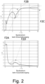
- the Figure 2 shows a schematic representation of a coil current for a switching on or off process of an electromechanical relay according to an embodiment of the present invention.
- the current behaves like a real coil and increases accordingly from 1 ms to about 4 ms. From about 5 ms onwards, the current decreases. This is because a magnetic armature is moved through the magnetic field of the coil and in turn changes the remanence of the magnetic circuit. The latter leads to the observable reduction in the current.
- the armature After a few milliseconds, the armature reaches its end position, meaning that the remanence is no longer changed and the current can rise again according to a real coil.
- the reaching of the end position can be identified as a local minimum.
- the coil current at switch-on contains a wealth of information about the electromechanical actuator, including the speed of movement, period of movement, temperature, armature impact and 'counterforces' after impact.
- the current When switching off, it can be seen that the current initially drops according to a real coil. However, from around 3 ms onwards, an increase in the current can be observed; here, a current is induced by the return movement of the armature to the rest position. After the local maximum, the current drops again according to a real coil. Thus, the coil current also contains a large amount of relevant information about the electromechanical actuator when switching off.
- This information is to be used with the present invention as black box modeling using machine learning methods to predict the state of the electromechanical actuators.
- the coil current can be used to determine the coil temperature and thus the actuator temperature.
- the armature is moved to its rest position after switching off the supply voltage, thereby inducing a current in the coil
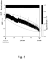
- the Figure 3 shows a schematic representation of a coil current of a relay in the switch-off process as an example over the entire service life according to an embodiment of the present invention.
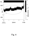
- the Figure 4 shows a schematic representation of a coil current of a relay in the switch-off process as an example over the entire service life according to an embodiment of the present invention.
- the Figure 5 shows a schematic representation of a diagram containing the predictions for a relay over its entire lifetime according to an embodiment of the present invention.
- the remaining lifetime is determined as the relative proportion of the remaining switching cycles to the total switching cycles estimated, with this value a long-term maintenance planning can be carried out, since a degeneration rate can be determined from the predictions and thus the remaining cycles or time can be calculated. Furthermore, the failure risk is estimated, for example, short-term abnormal changes in the coil current shape are taken into account.
- This target value is suitable for initiating maintenance measures at short notice in order to prevent a failure of the actuator and thus of the system.
- a replacement notice is issued due to a failure risk > 50%.
- a degeneration rate can be calculated with which the time or cycles until failure can be approximated.
- the Figure 6 shows a schematic representation of a diagram containing the predictions for a relay over its entire lifetime according to an embodiment of the present invention.
- the remaining service life is estimated to be more than 80% over the entire service life.
- Long-term maintenance planning based on this prediction is not possible in this case. Physically, this observation can be explained by the fact that the relay did not fail due to long-term degeneration, but rather a short-term effect, such as sticking of the contacts, led to the failure.
- a replacement notice is issued for the electromechanical device 1000 due to a failure risk > 50% based on the current operating status of the electromechanical device 1000.
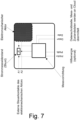
- the Figure 7 shows a schematic representation of a device according to an embodiment of the present invention.
- FIG 7 A minimal example of a structure according to the invention is outlined.
- a relay socket is used here, which converts the coil current via a measuring resistor (shunt) into a voltage, which is digitally recorded by a measuring device and passed on via an interface (Data+ Data-). Additional data can be added such as time stamps, temperatures, etc.
- the auxiliary energy can either be added externally (PWR+ PWR-) or it is taken from the coil control signal at A1 and A2.
- the evaluation device is executed externally as software in another module or in the cloud.
- the inputs of the machine learning processes are obtained through the interface described above.
- a return channel is optional to visually display the status on the relay base or to enable intervention in the control system.
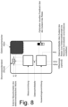
- the Figure 8 shows a schematic representation of a stand-alone relay socket according to an embodiment of the present invention.
- the relay used with the relay socket it may be useful to "marry” the relay used with the relay socket, For example, immediately after production and before delivery of the product to the customer, several switching cycles are run through and the neural network is "fine-tuned” precisely for this relay.
- the neural network could be retrained for the new relay at short notice. This can be done in a so-called initialization phase.
- additional information about the relay e.g. manufacturer code
- additional information about the relay is manually entered into the relay socket via an additional data interface so that the prognosis of the neural network is improved.
- the additional optional data interface can be useful for providing information about the status of the relay to a higher-level network. It is also conceivable that "updates" are transmitted to the relay socket via the interface.
- the Figure 9 shows a schematic representation of a modification of the relay socket Figure 8 according to an embodiment of the present invention.
- Figure 9 is a modification of the relay socket from Figure 8 presented in such a way that it is shown that in addition to the coil current, other measuring technology can also be integrated in the relay socket.
- the possibilities here are diverse and briefly in the Figure 9 described. It can be provided that appropriate circuit technology can advantageously be used to obtain information on the switching time of the contact without having to carry out complex direct measuring technology on the contact side.
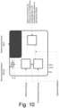
- the Figure 10 shows a schematic representation of an arrangement in which several relay sockets are connected to one another via a local communication bus, according to an embodiment of the present invention.
- FIG 10 Several relay sockets are connected to one another via a local communication bus and the individual measurement data from the relay sockets are managed by a central head module.
- the evaluation device can be installed in the head module so that several electromechanical actuators share one evaluation device. This approach is particularly cost-effective.
- the head module can be equipped with an additional data interface to communicate data externally.
- the data of the individual relays are only collected and/or preprocessed by the head module and a part of the evaluation device is executed externally as software.
- the Figure 11 shows the operation of the evaluation device according to an embodiment of the present invention.
- FIG 11 the functionality of the evaluation device is shown. There are three subsystems, all of which can be executed as pure software and can therefore be run on any end device; from microprocessors to cloud servers to local computers, various systems are provided for execution in different embodiments of the present invention.
- Data is fed into the evaluation device, such as time series of coil current and voltage and associated metadata.
- This data must first be preprocessed in a module set up for this purpose, such as a data preprocessing module, so that the data is standardized or outliers are eliminated.
- Machine learning methods are then used to predict the above-mentioned outputs. This step is shown with several modules arranged in series, since different machine learning methods may be necessary for the outputs.
- the predictions are ultimately used in the action recommendation module to make concrete recommendations for action, such as 'changing the actuator'.
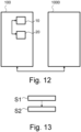
- the Fig. 12 shows a schematic representation of a device 100 for detecting wear of an electromechanical device 1000 according to an embodiment of the present invention.
- the device 100 comprises a measuring device 10 and an evaluation device 20.
- the measuring device 10 is designed to detect at least one predetermined operating parameter of the electromechanical device 1000.
- the evaluation device 20 is designed to use machine learning with the aid of mass data, preferably in the form of training data, to determine from the recorded predetermined operating parameters of the electromechanical Device to determine the current operating state of the electromechanical device.
- the present method makes it possible to provide wear detection, i.e. monitoring of wear or the wear behavior of an electromechanical device or an electromechanical switching device.
- the measuring device 10 is designed, for example, as a measuring device for detecting an operating parameter, such as an event, i.e. a switching operation of the electromechanical device, a temperature increase of the electromechanical device, or even a removal or failure of the electromechanical device in the form of the relay.
- an operating parameter such as an event, i.e. a switching operation of the electromechanical device, a temperature increase of the electromechanical device, or even a removal or failure of the electromechanical device in the form of the relay.
- the measuring device 10 is designed, for example, as a measuring device for detecting a curve and/or one or more characteristic variables of the event.
- the evaluation device 20 is designed, for example, to assign digital representative data to the current event or the current operating parameter.
- the representative data and/or the training data and/or state data can be fed into the artificial neural network.
- the event or operating parameter can be, for example, a coil current at the moment of switching on, or several electrical or physical quantities can be combined to form an operating parameter, such as coil current and contact voltage.
- the operating parameter can also be a calculated value such as a determined overstroke.
- the Fig. 13 shows a schematic representation of a flow chart of a method for detecting wear of an electromechanical device according to an embodiment of the present invention.
- At least one predetermined operating parameter of the electromechanical device 1000 is detected S1 by means of a measuring device 10.
- a current operating state of the electromechanical device 1000 is determined S2 using machine learning with the aid of mass data, preferably in the form of training data, from the recorded predetermined operating parameters of the electromechanical switching device 1000 by means of an evaluation device.
- control level it is also conceivable to use a control level to enable information to be obtained automatically from a control system or manually by a user as needed. Special queries such as an estimate of the load or the probability of survival in the next week would be conceivable in this way.
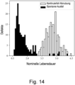
- the Fig. 14 shows a schematic representation of an error distribution or failure distribution for wear of an electromechanical device according to an embodiment of the present invention.
- the RUL of the electromechanical device 1000 is a typical target value in the context of predictive maintenance. Measurement data of the operation of the electromechanical device 1000 are used as input and the remaining useful life, RUL, and the risk of failure, FR, of the electromechanical device 1000 are predicted as output.
- the multimodal error distribution or failure distribution shown illustrates a continuous degeneration of the electromechanical device 1000 and a spontaneous failure of the electromechanical device 1000 according to an embodiment of the present invention.
- the failure distribution shown is often referred to as a bathtub curve and characterizes the multimodal error or failure distribution, so that the evaluation device 20 is designed to determine the current operating state from the detected predetermined operating parameter via a plurality of target variables, wherein preferably the plurality of target variables correspond to a multimodal failure distribution.
- the underlying data of the Fig. 14 The multimodal error distribution shown can be used as training or mass data for the training procedure for training a estimator with operating data on different degrees of wear for a device for detecting wear of an electromechanical device.
Landscapes
- Physics & Mathematics (AREA)
- General Physics & Mathematics (AREA)
- Engineering & Computer Science (AREA)
- Theoretical Computer Science (AREA)
- Testing Of Devices, Machine Parts, Or Other Structures Thereof (AREA)
Claims (15)
- Dispositif (100) de détection d'usure d'un dispositif électromécanique (1000), dans lequel le dispositif (100) comprend :un dispositif de mesure (10) qui est conçu pour acquérir au moins un paramètre de fonctionnement prédéterminé du dispositif électromécanique (1000) ; etun dispositif d'évaluation (20) qui est conçu pour déterminer un état de fonctionnement actuel du dispositif électromécanique (1000) à partir du paramètre de fonctionnement prédéterminé acquis du dispositif électromécanique (1000), par un apprentissage automatique à l'aide de mégadonnées, de préférence sous forme de données d'apprentissage ;caractérisé en ce que le dispositif d'évaluation (20) est conçu pour déterminer l'état de fonctionnement actuel à partir du paramètre de fonctionnement prédéterminé acquis, en supposant une distribution de défaillances multimodale.
- Dispositif (100) selon la revendication de brevet 1,
dans lequel le dispositif d'évaluation (20) est conçu pour appliquer, pour l'apprentissage automatique, un estimateur entraîné avec des données de fonctionnement à différents degrés d'usure, et pour utiliser l'estimateur entraîné pour déterminer l'état de fonctionnement actuel du dispositif électromécanique (1000). - Dispositif (100) selon la revendication de brevet 2,
dans lequel l'estimateur est conçu comme un estimateur de classification et/ou de régression. - Dispositif (100) selon la revendication de brevet 2 ou 3,
dans lequel l'estimateur comprend un réseau neuronal profond comprenant des couches de convolution et/ou des couches récurrentes. - Dispositif (100) selon l'une des revendications de brevet précédentes,
dans lequel le dispositif d'évaluation (20) est conçu pour déterminer l'état de fonctionnement actuel à partir du paramètre de fonctionnement prédéterminé acquis par une pluralité de grandeurs cibles, dans lequel la pluralité de grandeurs cibles correspondent, de manière particulièrement préférée, à une distribution de défaillances multimodale. - Dispositif (100) selon l'une des revendications de brevet précédentes,dans lequel le dispositif de mesure (10) est en outre conçu pour ajouter des informations supplémentaires ayant la forme d'un horodatage ou d'un état de compteur au au moins un paramètre de fonctionnement prédéterminé acquis du dispositif électromécanique,dans lequel le dispositif de mesure (10) est en outre de préférence conçu pour acquérir en continu le paramètre de fonctionnement du dispositif électromécanique ou pour acquérir le paramètre de fonctionnement uniquement en cas d'événement de commutation du dispositif électromécanique.
- Dispositif (100) selon l'une des revendications de brevet précédentes,
dans lequel le dispositif d'évaluation (20) est conçu pour déterminer en outre des prédictions concernant un état de fonctionnement futur du dispositif électromécanique (1000). - Dispositif (100) selon l'une des revendications de brevet précédentes,
dans lequel le dispositif d'évaluation (20) est conçu pour déterminer l'état de fonctionnement actuel ou les prédictions concernant le futur état de fonctionnement du dispositif électromécanique (1000) après l'écoulement d'une période de temps ou déclenchement par un événement déclencheur. - Dispositif (100) selon la revendication de brevet 7 ou 8, dans lequel sont prévus en tant que prédictions :- une durée de vie utile restante en part relative de la durée de vie totale du dispositif électromécanique (1000) ;- une durée de vie utile restante en part absolue de cycles ou de temps d'utilisation du dispositif électromécanique (1000) ;- une probabilité de risque de défaillance spontanée du dispositif électromécanique (1000) ;- un type de dispositif électromécanique (1000) ;- un coefficient pour une charge ou une classification d'une charge du dispositif électromécanique (1000) ;- un message d'erreur codé binaire ;- une disponibilité opérationnelle codée binaire ; et/ou- des informations associées à un processus du dispositif électromécanique (1000).
- Dispositif (100) selon l'une des revendications de brevet précédentes,
dans lequel le dispositif d'évaluation (20) est conçu pour être intégré dans un dispositif de châssis pour le dispositif électromécanique (1000). - Dispositif (100) selon l'une des revendications de brevet précédentes,
dans lequel le dispositif (100) comprend en outre un dispositif d'affichage qui est de préférence conçu pour afficher l'état de fonctionnement actuel du dispositif électromécanique (1000). - Dispositif (100) selon l'une des revendications de brevet précédentes,dans lequel le au moins un paramètre de fonctionnement prédéterminé du dispositif électromécanique (1000) comprend une force d'actionnement, une force de réaction, une course d'actionnement, une surcourse, un point de commutation, une impulsion lumineuse, un arc électrique, un signal acoustique, un champ magnétique, une température, un courant de bobine, une tension de bobine, un courant de contact, un courant de charge ou une tension de contact ; et/oudans lequel les mégadonnées comprennent des paramètres de fonctionnement quelconques et les paramètres de fonctionnement quelconques comprennent une force d'actionnement, une force de réaction, une course d'actionnement, une surcourse, un point de commutation, une impulsion lumineuse, un arc électrique, un signal acoustique, un champ magnétique, une température, un courant de bobine, une tension de bobine, un courant de contact, un courant de charge ou une tension de contact du dispositif électromécanique (1000).
- Dispositif (100) selon l'une des revendications de brevet précédentes,
dans lequel le dispositif de mesure (10) est conçu pour acquérir les paramètres de fonctionnement quelconques sous forme de courbes caractéristiques sur la base d'une mesure préalable au cours d'une phase d'initialisation du dispositif électromécanique (1000). - Procédé de détection d'usure d'un dispositif électromécanique (1000), dans lequel le procédé comprend les étapes de procédé suivantes :acquérir (S1) au moins un paramètre de fonctionnement prédéterminé du dispositif électromécanique (1000) au moyen d'un dispositif de mesure (10) ; etdéterminer (S2), au moyen d'un dispositif d'évaluation (20), un état de fonctionnement actuel du dispositif électromécanique (1000) par un apprentissage automatique à l'aide de mégadonnées, de préférence sous forme de données d'apprentissage, à partir du paramètre de fonctionnement prédéterminé acquis du dispositif de commutation électromécanique (1000) ;caractérisé en ce que l'état de fonctionnement actuel est déterminé à partir du paramètre de fonctionnement prédéterminé acquis en supposant une distribution de défaillances multimodale.
- Procédé d'apprentissage pour l'apprentissage d'un estimateur avec des données de fonctionnement à différents degrés d'usure pour un dispositif de détection d'usure d'un dispositif électromécanique selon l'une des revendications de brevet 1 à 13 précédentes.
Applications Claiming Priority (2)
| Application Number | Priority Date | Filing Date | Title |
|---|---|---|---|
| BE20215335A BE1029357B1 (de) | 2021-04-30 | 2021-04-30 | Vorrichtung und Verfahren zum Erkennen einer Abnutzung einer elektromechanischen Einrichtung |
| PCT/EP2022/061237 WO2022229274A1 (fr) | 2021-04-30 | 2022-04-27 | Dispositif et procédé permettant de détecter de l'usure dans un appareil électromécanique |
Publications (2)
| Publication Number | Publication Date |
|---|---|
| EP4330694A1 EP4330694A1 (fr) | 2024-03-06 |
| EP4330694B1 true EP4330694B1 (fr) | 2025-03-05 |
Family
ID=75825412
Family Applications (1)
| Application Number | Title | Priority Date | Filing Date |
|---|---|---|---|
| EP22725876.1A Active EP4330694B1 (fr) | 2021-04-30 | 2022-04-27 | Dispositif et procédé permettant de détecter de l'usure dans un appareil électromécanique |
Country Status (5)
| Country | Link |
|---|---|
| US (1) | US12591010B2 (fr) |
| EP (1) | EP4330694B1 (fr) |
| CN (1) | CN117222900A (fr) |
| BE (1) | BE1029357B1 (fr) |
| WO (1) | WO2022229274A1 (fr) |
Families Citing this family (3)
| Publication number | Priority date | Publication date | Assignee | Title |
|---|---|---|---|---|
| BE1030869B1 (de) * | 2022-09-12 | 2024-04-09 | Phoenix Contact Gmbh & Co | Verfahren zur Ansteuerung eines elektromechanischen Schaltelements |
| LU503757B1 (de) * | 2023-03-29 | 2024-09-30 | Phoenix Contact Gmbh & Co | Verfahren, Vorrichtung und Computerprogramm zur Identifizierung und Ansteuerung elektromechanischer Bauteile |
| FR3155357A1 (fr) * | 2023-11-10 | 2025-05-16 | Safran Electrical & Power | Appareil comprenant un contact électrique muni d’un capteur de luminosité et procédé d’estimation d’usure |
Family Cites Families (24)
| Publication number | Priority date | Publication date | Assignee | Title |
|---|---|---|---|---|
| US6199018B1 (en) * | 1998-03-04 | 2001-03-06 | Emerson Electric Co. | Distributed diagnostic system |
| US6917203B1 (en) * | 2001-09-07 | 2005-07-12 | The United States Of America As Represented By The Administrator Of The National Aeronautics And Space Administration | Current signature sensor |
| DE20310043U1 (de) | 2003-06-30 | 2004-11-11 | Dewert Antriebs- Und Systemtechnik Gmbh & Co. Kg | Kontrolleinrichtung für Relais |
| DE102010041998A1 (de) | 2010-10-05 | 2012-04-05 | Robert Bosch Gmbh | Verfahren zur Vorhersage der Einsatzfähigkeit eines Relais oder eines Schützes |
| DE102013219243B4 (de) | 2013-09-25 | 2018-01-18 | Robert Bosch Gmbh | Verfahren und Einrichtung zur Bestimmung der Alterung eines elektronischen Unterbrechungselements, insbesondere eines Leistungsschützes |
| EP2988187B1 (fr) * | 2014-08-22 | 2017-03-29 | ABB Schweiz AG | Procédé pour évaluer l'état de machines rotatives reliées à un moteur électrique |
| US20160125993A1 (en) | 2014-11-03 | 2016-05-05 | Texas Instruments Incorporated | Detection of plunger movement in dc solenoids through current sense technique |
| BR112018009766A8 (pt) | 2015-12-01 | 2019-02-26 | General Electric Technology Gmbh | método de avaliação inteligente de condição de isolamento principal de isolamento de papel e óleo de transformador |
| US10586153B2 (en) * | 2016-06-16 | 2020-03-10 | Qatar University | Method and apparatus for performing motor-fault detection via convolutional neural networks |
| DE102016124083B4 (de) | 2016-12-12 | 2018-07-05 | Phoenix Contact Gmbh & Co. Kg | Verfahren zur Überwachung einer elektromechanischen Komponente eines Automatisierungssystems |
| FR3060758B1 (fr) | 2016-12-16 | 2021-01-08 | Schneider Electric Ind Sas | Procede et dispositif de diagnostic d'usure d'un appareil electrique de coupure, et appareil electrique comportant un tel dispositif |
| EP3379357B1 (fr) | 2017-03-24 | 2019-07-10 | ABB Schweiz AG | Système informatique et procédé de surveillance de l'état de systèmes de processus industriel |
| DE102017222498B4 (de) * | 2017-12-12 | 2019-09-05 | Baumüller Nürnberg GmbH | Verfahren zum Betrieb eines elektromotorischen Antriebssystems und danach arbeitendes elektromotorisches Antriebssystem |
| US10296848B1 (en) * | 2018-03-05 | 2019-05-21 | Clinc, Inc. | Systems and method for automatically configuring machine learning models |
| WO2019186453A1 (fr) * | 2018-03-28 | 2019-10-03 | L&T Technology Services Limited | Système et procédé de surveillance de la santé et de prédiction de défaillance d'une machine électromécanique |
| DE102018114425A1 (de) | 2018-06-15 | 2019-12-19 | Phoenix Contact Gmbh & Co. Kg | Schaltüberwachungsvorrichtung |
| CN109061474A (zh) * | 2018-10-15 | 2018-12-21 | 株洲中车时代电气股份有限公司 | 一种电机轴承故障诊断装置 |
| BE1026844B1 (de) * | 2018-12-07 | 2020-07-08 | Phoenix Contact Gmbh & Co | Vorrichtung und Verfahren zur Verschleißerkennung einer elektromechanischen Schalteinrichtung |
| DE102018221270A1 (de) * | 2018-12-07 | 2020-06-10 | Phoenix Contact Gmbh & Co. Kg | Vorrichtung und Verfahren zur Verschleißerkennung einer elektromechanischen Schalteinrichtung |
| DE102019114211A1 (de) * | 2019-05-28 | 2020-12-03 | Phoenix Contact Gmbh & Co. Kg | Techniken zur Ausfallvorhersage von Elementarrelais |
| EP3764179B1 (fr) | 2019-07-08 | 2024-11-13 | ABB Schweiz AG | Évaluation des conditions d'équipement et processus industriels |
| DE102019215902A1 (de) * | 2019-10-16 | 2021-05-20 | Robert Bosch Gmbh | Verfahren zur Bestimmung eines Gütegrades von Daten-Sätzen von Sensoren |
| CN111310314B (zh) * | 2020-01-21 | 2022-04-08 | 北京瑞风协同科技股份有限公司 | 一种基于人工智能确定机电装置寿命的方法和系统 |
| US12554980B2 (en) * | 2021-03-03 | 2026-02-17 | International Business Machines Corporation | Estimating remaining useful life based on operation and degradation characteristics |
-
2021
- 2021-04-30 BE BE20215335A patent/BE1029357B1/de not_active IP Right Cessation
-
2022
- 2022-04-27 US US18/557,780 patent/US12591010B2/en active Active
- 2022-04-27 WO PCT/EP2022/061237 patent/WO2022229274A1/fr not_active Ceased
- 2022-04-27 CN CN202280031843.0A patent/CN117222900A/zh active Pending
- 2022-04-27 EP EP22725876.1A patent/EP4330694B1/fr active Active
Also Published As
| Publication number | Publication date |
|---|---|
| US20240426910A1 (en) | 2024-12-26 |
| BE1029357A1 (de) | 2022-11-29 |
| CN117222900A (zh) | 2023-12-12 |
| WO2022229274A1 (fr) | 2022-11-03 |
| EP4330694A1 (fr) | 2024-03-06 |
| US12591010B2 (en) | 2026-03-31 |
| BE1029357B1 (de) | 2022-12-05 |
Similar Documents
| Publication | Publication Date | Title |
|---|---|---|
| DE102021111192A1 (de) | Vorrichtung und Verfahren zum Erkennen einer Abnutzung einer elektromechanischen Einrichtung | |
| BE1026844B1 (de) | Vorrichtung und Verfahren zur Verschleißerkennung einer elektromechanischen Schalteinrichtung | |
| BE1029357B1 (de) | Vorrichtung und Verfahren zum Erkennen einer Abnutzung einer elektromechanischen Einrichtung | |
| EP1543394B1 (fr) | Procede et dispositif pour surveiller une installation technique comprenant plusieurs systemes, notamment une centrale electrique | |
| EP3745229B1 (fr) | Procédés et dispositif de prévision du défaut d' un relais élémentaire | |
| WO2020109108A1 (fr) | Procédé permettant de surveiller un accumulateur d'énergie dans un réseau de bord | |
| DE102017203836A1 (de) | Verfahren und System zum Bestimmen einer erwarteten Lebensdauer eines elektrischen Betriebsmittels | |
| WO2020216530A1 (fr) | Procédé servant à définir des cycles d'utilisation restante, circuit de définition de cycle d'utilisation restante, dispositif de définition de cycle d'utilisation restante | |
| DE102018221270A1 (de) | Vorrichtung und Verfahren zur Verschleißerkennung einer elektromechanischen Schalteinrichtung | |
| EP3574458B1 (fr) | Procédé de planification d'équipement de fonctionnement d'un système électrique destiné à l'alimentation électrique et système électrique destiné à l'alimentation électrique | |
| EP3975066A1 (fr) | Procédé de vérification d'une fonction technique d'un premier dispositif électrique et/ou mécanique d'un système ferroviaire | |
| LU93350B1 (de) | Verfahren zur Überwachung einer elektromechanischen Komponente eines Automatisierungssystems | |
| DE102023113137A1 (de) | Verfahren und Vorrichtung zur Erfassung von Messdaten einer Maschine sowie Reifenheizpresse aufweisend eine Vorrichtung zur Erfassung von Messdaten | |
| EP3977496B1 (fr) | Procédé de prédiction de défaillance d'un relais élémentaire | |
| DE102023205186B3 (de) | Leistungsschalter | |
| DE19853511C2 (de) | Verfahren zur zustandsorientierten Instandhaltung von Leistungsschaltern und Meß- und Prüfeinrichtung zur Durchführung des Verfahrens | |
| EP3418126A1 (fr) | Procédé de fonctionnement d'un circuit de bord | |
| EP3959571A1 (fr) | Procédé servant à définir des cycles d'utilisation restante, circuit de définition de cycle d'utilisation restante, dispositif de définition de cycle d'utilisation restante | |
| LU503757B1 (de) | Verfahren, Vorrichtung und Computerprogramm zur Identifizierung und Ansteuerung elektromechanischer Bauteile | |
| EP1376282A2 (fr) | Système de contrôle avec surveillance d'actionneur | |
| DE102016124079A1 (de) | Verfahren zur Überwachung einer elektromechanischen Komponente eines Automatisierungssystems | |
| WO2023241974A1 (fr) | Dispositif de surveillance pour une électrovanne d'un système à air comprimé de véhicule, système composé de l'électrovanne, du dispositif de surveillance et d'un dispositif de commande, et procédé de surveillance de l'électrovanne | |
| EP3929683A1 (fr) | Procédé de maintenance en fonction de l'état d'un dispositif d'accès | |
| WO2023247269A1 (fr) | Procédé permettant de faire fonctionner un circuit comprenant au moins un composant de puissance | |
| WO2024208494A1 (fr) | Procédé de fonctionnement d'un système faisant appel à un jumeau numérique |
Legal Events
| Date | Code | Title | Description |
|---|---|---|---|
| STAA | Information on the status of an ep patent application or granted ep patent |
Free format text: STATUS: UNKNOWN |
|
| STAA | Information on the status of an ep patent application or granted ep patent |
Free format text: STATUS: THE INTERNATIONAL PUBLICATION HAS BEEN MADE |
|
| PUAI | Public reference made under article 153(3) epc to a published international application that has entered the european phase |
Free format text: ORIGINAL CODE: 0009012 |
|
| STAA | Information on the status of an ep patent application or granted ep patent |
Free format text: STATUS: REQUEST FOR EXAMINATION WAS MADE |
|
| 17P | Request for examination filed |
Effective date: 20231120 |
|
| AK | Designated contracting states |
Kind code of ref document: A1 Designated state(s): AL AT BE BG CH CY CZ DE DK EE ES FI FR GB GR HR HU IE IS IT LI LT LU LV MC MK MT NL NO PL PT RO RS SE SI SK SM TR |
|
| DAV | Request for validation of the european patent (deleted) | ||
| DAX | Request for extension of the european patent (deleted) | ||
| GRAP | Despatch of communication of intention to grant a patent |
Free format text: ORIGINAL CODE: EPIDOSNIGR1 |
|
| STAA | Information on the status of an ep patent application or granted ep patent |
Free format text: STATUS: GRANT OF PATENT IS INTENDED |
|
| INTG | Intention to grant announced |
Effective date: 20241004 |
|
| RAP3 | Party data changed (applicant data changed or rights of an application transferred) |
Owner name: PHOENIX CONTACT GMBH & CO. KG |
|
| P01 | Opt-out of the competence of the unified patent court (upc) registered |
Free format text: CASE NUMBER: APP_62265/2024 Effective date: 20241121 |
|
| GRAS | Grant fee paid |
Free format text: ORIGINAL CODE: EPIDOSNIGR3 |
|
| GRAA | (expected) grant |
Free format text: ORIGINAL CODE: 0009210 |
|
| STAA | Information on the status of an ep patent application or granted ep patent |
Free format text: STATUS: THE PATENT HAS BEEN GRANTED |
|
| AK | Designated contracting states |
Kind code of ref document: B1 Designated state(s): AL AT BE BG CH CY CZ DE DK EE ES FI FR GB GR HR HU IE IS IT LI LT LU LV MC MK MT NL NO PL PT RO RS SE SI SK SM TR |
|
| REG | Reference to a national code |
Ref country code: GB Ref legal event code: FG4D Free format text: NOT ENGLISH |
|
| REG | Reference to a national code |
Ref country code: CH Ref legal event code: EP |
|
| REG | Reference to a national code |
Ref country code: IE Ref legal event code: FG4D Free format text: LANGUAGE OF EP DOCUMENT: GERMAN |
|
| REG | Reference to a national code |
Ref country code: DE Ref legal event code: R096 Ref document number: 502022003107 Country of ref document: DE |
|
| PG25 | Lapsed in a contracting state [announced via postgrant information from national office to epo] |
Ref country code: RS Free format text: LAPSE BECAUSE OF FAILURE TO SUBMIT A TRANSLATION OF THE DESCRIPTION OR TO PAY THE FEE WITHIN THE PRESCRIBED TIME-LIMIT Effective date: 20250605 |
|
| PG25 | Lapsed in a contracting state [announced via postgrant information from national office to epo] |
Ref country code: FI Free format text: LAPSE BECAUSE OF FAILURE TO SUBMIT A TRANSLATION OF THE DESCRIPTION OR TO PAY THE FEE WITHIN THE PRESCRIBED TIME-LIMIT Effective date: 20250305 |
|
| REG | Reference to a national code |
Ref country code: NL Ref legal event code: MP Effective date: 20250305 |
|
| PG25 | Lapsed in a contracting state [announced via postgrant information from national office to epo] |
Ref country code: ES Free format text: LAPSE BECAUSE OF FAILURE TO SUBMIT A TRANSLATION OF THE DESCRIPTION OR TO PAY THE FEE WITHIN THE PRESCRIBED TIME-LIMIT Effective date: 20250305 |
|
| REG | Reference to a national code |
Ref country code: LT Ref legal event code: MG9D |
|
| PG25 | Lapsed in a contracting state [announced via postgrant information from national office to epo] |
Ref country code: NO Free format text: LAPSE BECAUSE OF FAILURE TO SUBMIT A TRANSLATION OF THE DESCRIPTION OR TO PAY THE FEE WITHIN THE PRESCRIBED TIME-LIMIT Effective date: 20250605 |
|
| PG25 | Lapsed in a contracting state [announced via postgrant information from national office to epo] |
Ref country code: HR Free format text: LAPSE BECAUSE OF FAILURE TO SUBMIT A TRANSLATION OF THE DESCRIPTION OR TO PAY THE FEE WITHIN THE PRESCRIBED TIME-LIMIT Effective date: 20250305 |
|
| PG25 | Lapsed in a contracting state [announced via postgrant information from national office to epo] |
Ref country code: LV Free format text: LAPSE BECAUSE OF FAILURE TO SUBMIT A TRANSLATION OF THE DESCRIPTION OR TO PAY THE FEE WITHIN THE PRESCRIBED TIME-LIMIT Effective date: 20250305 |
|
| PG25 | Lapsed in a contracting state [announced via postgrant information from national office to epo] |
Ref country code: BG Free format text: LAPSE BECAUSE OF FAILURE TO SUBMIT A TRANSLATION OF THE DESCRIPTION OR TO PAY THE FEE WITHIN THE PRESCRIBED TIME-LIMIT Effective date: 20250305 Ref country code: GR Free format text: LAPSE BECAUSE OF FAILURE TO SUBMIT A TRANSLATION OF THE DESCRIPTION OR TO PAY THE FEE WITHIN THE PRESCRIBED TIME-LIMIT Effective date: 20250606 |
|
| PG25 | Lapsed in a contracting state [announced via postgrant information from national office to epo] |
Ref country code: NL Free format text: LAPSE BECAUSE OF FAILURE TO SUBMIT A TRANSLATION OF THE DESCRIPTION OR TO PAY THE FEE WITHIN THE PRESCRIBED TIME-LIMIT Effective date: 20250305 |
|
| PG25 | Lapsed in a contracting state [announced via postgrant information from national office to epo] |
Ref country code: SE Free format text: LAPSE BECAUSE OF FAILURE TO SUBMIT A TRANSLATION OF THE DESCRIPTION OR TO PAY THE FEE WITHIN THE PRESCRIBED TIME-LIMIT Effective date: 20250305 |
|
| PG25 | Lapsed in a contracting state [announced via postgrant information from national office to epo] |
Ref country code: SM Free format text: LAPSE BECAUSE OF FAILURE TO SUBMIT A TRANSLATION OF THE DESCRIPTION OR TO PAY THE FEE WITHIN THE PRESCRIBED TIME-LIMIT Effective date: 20250305 |
|
| PG25 | Lapsed in a contracting state [announced via postgrant information from national office to epo] |
Ref country code: PT Free format text: LAPSE BECAUSE OF FAILURE TO SUBMIT A TRANSLATION OF THE DESCRIPTION OR TO PAY THE FEE WITHIN THE PRESCRIBED TIME-LIMIT Effective date: 20250707 |
|
| PG25 | Lapsed in a contracting state [announced via postgrant information from national office to epo] |
Ref country code: PL Free format text: LAPSE BECAUSE OF FAILURE TO SUBMIT A TRANSLATION OF THE DESCRIPTION OR TO PAY THE FEE WITHIN THE PRESCRIBED TIME-LIMIT Effective date: 20250305 |
|
| PG25 | Lapsed in a contracting state [announced via postgrant information from national office to epo] |
Ref country code: EE Free format text: LAPSE BECAUSE OF FAILURE TO SUBMIT A TRANSLATION OF THE DESCRIPTION OR TO PAY THE FEE WITHIN THE PRESCRIBED TIME-LIMIT Effective date: 20250305 Ref country code: CZ Free format text: LAPSE BECAUSE OF FAILURE TO SUBMIT A TRANSLATION OF THE DESCRIPTION OR TO PAY THE FEE WITHIN THE PRESCRIBED TIME-LIMIT Effective date: 20250305 |
|
| PG25 | Lapsed in a contracting state [announced via postgrant information from national office to epo] |
Ref country code: RO Free format text: LAPSE BECAUSE OF FAILURE TO SUBMIT A TRANSLATION OF THE DESCRIPTION OR TO PAY THE FEE WITHIN THE PRESCRIBED TIME-LIMIT Effective date: 20250305 |
|
| PG25 | Lapsed in a contracting state [announced via postgrant information from national office to epo] |
Ref country code: SK Free format text: LAPSE BECAUSE OF FAILURE TO SUBMIT A TRANSLATION OF THE DESCRIPTION OR TO PAY THE FEE WITHIN THE PRESCRIBED TIME-LIMIT Effective date: 20250305 |
|
| PG25 | Lapsed in a contracting state [announced via postgrant information from national office to epo] |
Ref country code: IS Free format text: LAPSE BECAUSE OF FAILURE TO SUBMIT A TRANSLATION OF THE DESCRIPTION OR TO PAY THE FEE WITHIN THE PRESCRIBED TIME-LIMIT Effective date: 20250705 |
|
| REG | Reference to a national code |
Ref country code: CH Ref legal event code: H13 Free format text: ST27 STATUS EVENT CODE: U-0-0-H10-H13 (AS PROVIDED BY THE NATIONAL OFFICE) Effective date: 20251125 |
|
| REG | Reference to a national code |
Ref country code: DE Ref legal event code: R097 Ref document number: 502022003107 Country of ref document: DE |
|
| PG25 | Lapsed in a contracting state [announced via postgrant information from national office to epo] |
Ref country code: LU Free format text: LAPSE BECAUSE OF NON-PAYMENT OF DUE FEES Effective date: 20250427 |
|
| PG25 | Lapsed in a contracting state [announced via postgrant information from national office to epo] |
Ref country code: MC Free format text: LAPSE BECAUSE OF FAILURE TO SUBMIT A TRANSLATION OF THE DESCRIPTION OR TO PAY THE FEE WITHIN THE PRESCRIBED TIME-LIMIT Effective date: 20250305 |
|
| REG | Reference to a national code |
Ref country code: BE Ref legal event code: MM Effective date: 20250430 |
|
| PLBE | No opposition filed within time limit |
Free format text: ORIGINAL CODE: 0009261 |
|
| STAA | Information on the status of an ep patent application or granted ep patent |
Free format text: STATUS: NO OPPOSITION FILED WITHIN TIME LIMIT |
|
| PG25 | Lapsed in a contracting state [announced via postgrant information from national office to epo] |
Ref country code: DK Free format text: LAPSE BECAUSE OF FAILURE TO SUBMIT A TRANSLATION OF THE DESCRIPTION OR TO PAY THE FEE WITHIN THE PRESCRIBED TIME-LIMIT Effective date: 20250305 |
|
| REG | Reference to a national code |
Ref country code: CH Ref legal event code: L10 Free format text: ST27 STATUS EVENT CODE: U-0-0-L10-L00 (AS PROVIDED BY THE NATIONAL OFFICE) Effective date: 20260114 |
|
| PG25 | Lapsed in a contracting state [announced via postgrant information from national office to epo] |
Ref country code: BE Free format text: LAPSE BECAUSE OF NON-PAYMENT OF DUE FEES Effective date: 20250430 |
|
| PG25 | Lapsed in a contracting state [announced via postgrant information from national office to epo] |
Ref country code: CH Free format text: LAPSE BECAUSE OF NON-PAYMENT OF DUE FEES Effective date: 20250430 |
|
| 26N | No opposition filed |
Effective date: 20251208 |
|
| PG25 | Lapsed in a contracting state [announced via postgrant information from national office to epo] |
Ref country code: IE Free format text: LAPSE BECAUSE OF NON-PAYMENT OF DUE FEES Effective date: 20250427 |
|
| PG25 | Lapsed in a contracting state [announced via postgrant information from national office to epo] |
Ref country code: CY Free format text: LAPSE BECAUSE OF FAILURE TO SUBMIT A TRANSLATION OF THE DESCRIPTION OR TO PAY THE FEE WITHIN THE PRESCRIBED TIME-LIMIT Effective date: 20250305 |
|
| PG25 | Lapsed in a contracting state [announced via postgrant information from national office to epo] |
Ref country code: LT Free format text: LAPSE BECAUSE OF FAILURE TO SUBMIT A TRANSLATION OF THE DESCRIPTION OR TO PAY THE FEE WITHIN THE PRESCRIBED TIME-LIMIT Effective date: 20250305 |
|
| PGFP | Annual fee paid to national office [announced via postgrant information from national office to epo] |
Ref country code: IT Payment date: 20260422 Year of fee payment: 5 |
|
| PGFP | Annual fee paid to national office [announced via postgrant information from national office to epo] |
Ref country code: DE Payment date: 20260623 Year of fee payment: 5 |
|
| PGFP | Annual fee paid to national office [announced via postgrant information from national office to epo] |
Ref country code: AT Payment date: 20260714 Year of fee payment: 5 |
|
| PGFP | Annual fee paid to national office [announced via postgrant information from national office to epo] |
Ref country code: FR Payment date: 20260423 Year of fee payment: 5 |