EP1376446B1 - Verfahren und Vorrichtung zur Identifizierung von mehreren Gegenständen auf einem Transportband mit Transpondern - Google Patents
Verfahren und Vorrichtung zur Identifizierung von mehreren Gegenständen auf einem Transportband mit Transpondern Download PDFInfo
- Publication number
- EP1376446B1 EP1376446B1 EP03253967A EP03253967A EP1376446B1 EP 1376446 B1 EP1376446 B1 EP 1376446B1 EP 03253967 A EP03253967 A EP 03253967A EP 03253967 A EP03253967 A EP 03253967A EP 1376446 B1 EP1376446 B1 EP 1376446B1
- Authority
- EP
- European Patent Office
- Prior art keywords
- antenna
- coils
- coil
- transponders
- substrate
- Prior art date
- Legal status (The legal status is an assumption and is not a legal conclusion. Google has not performed a legal analysis and makes no representation as to the accuracy of the status listed.)
- Expired - Lifetime
Links
Images




Classifications
-
- G—PHYSICS
- G06—COMPUTING OR CALCULATING; COUNTING
- G06K—GRAPHICAL DATA READING; PRESENTATION OF DATA; RECORD CARRIERS; HANDLING RECORD CARRIERS
- G06K19/00—Record carriers for use with machines and with at least a part designed to carry digital markings
- G06K19/06—Record carriers for use with machines and with at least a part designed to carry digital markings characterised by the kind of the digital marking, e.g. shape, nature, code
- G06K19/067—Record carriers with conductive marks, printed circuits or semiconductor circuit elements, e.g. credit or identity cards also with resonating or responding marks without active components
- G06K19/07—Record carriers with conductive marks, printed circuits or semiconductor circuit elements, e.g. credit or identity cards also with resonating or responding marks without active components with integrated circuit chips
- G06K19/077—Constructional details, e.g. mounting of circuits in the carrier
- G06K19/07749—Constructional details, e.g. mounting of circuits in the carrier the record carrier being capable of non-contact communication, e.g. constructional details of the antenna of a non-contact smart card
-
- G—PHYSICS
- G06—COMPUTING OR CALCULATING; COUNTING
- G06K—GRAPHICAL DATA READING; PRESENTATION OF DATA; RECORD CARRIERS; HANDLING RECORD CARRIERS
- G06K19/00—Record carriers for use with machines and with at least a part designed to carry digital markings
- G06K19/04—Record carriers for use with machines and with at least a part designed to carry digital markings characterised by the shape
- G06K19/041—Constructional details
-
- G—PHYSICS
- G06—COMPUTING OR CALCULATING; COUNTING
- G06K—GRAPHICAL DATA READING; PRESENTATION OF DATA; RECORD CARRIERS; HANDLING RECORD CARRIERS
- G06K19/00—Record carriers for use with machines and with at least a part designed to carry digital markings
- G06K19/06—Record carriers for use with machines and with at least a part designed to carry digital markings characterised by the kind of the digital marking, e.g. shape, nature, code
- G06K19/067—Record carriers with conductive marks, printed circuits or semiconductor circuit elements, e.g. credit or identity cards also with resonating or responding marks without active components
- G06K19/07—Record carriers with conductive marks, printed circuits or semiconductor circuit elements, e.g. credit or identity cards also with resonating or responding marks without active components with integrated circuit chips
- G06K19/077—Constructional details, e.g. mounting of circuits in the carrier
- G06K19/07749—Constructional details, e.g. mounting of circuits in the carrier the record carrier being capable of non-contact communication, e.g. constructional details of the antenna of a non-contact smart card
- G06K19/07758—Constructional details, e.g. mounting of circuits in the carrier the record carrier being capable of non-contact communication, e.g. constructional details of the antenna of a non-contact smart card arrangements for adhering the record carrier to further objects or living beings, functioning as an identification tag
-
- G—PHYSICS
- G06—COMPUTING OR CALCULATING; COUNTING
- G06K—GRAPHICAL DATA READING; PRESENTATION OF DATA; RECORD CARRIERS; HANDLING RECORD CARRIERS
- G06K7/00—Methods or arrangements for sensing record carriers, e.g. for reading patterns
- G06K7/0008—General problems related to the reading of electronic memory record carriers, independent of its reading method, e.g. power transfer
-
- G—PHYSICS
- G06—COMPUTING OR CALCULATING; COUNTING
- G06K—GRAPHICAL DATA READING; PRESENTATION OF DATA; RECORD CARRIERS; HANDLING RECORD CARRIERS
- G06K7/00—Methods or arrangements for sensing record carriers, e.g. for reading patterns
- G06K7/10—Methods or arrangements for sensing record carriers, e.g. for reading patterns by electromagnetic radiation, e.g. optical sensing; by corpuscular radiation
- G06K7/10009—Methods or arrangements for sensing record carriers, e.g. for reading patterns by electromagnetic radiation, e.g. optical sensing; by corpuscular radiation sensing by radiation using wavelengths larger than 0.1 mm, e.g. radio-waves or microwaves
- G06K7/10316—Methods or arrangements for sensing record carriers, e.g. for reading patterns by electromagnetic radiation, e.g. optical sensing; by corpuscular radiation sensing by radiation using wavelengths larger than 0.1 mm, e.g. radio-waves or microwaves using at least one antenna particularly designed for interrogating the wireless record carriers
- G06K7/10336—Methods or arrangements for sensing record carriers, e.g. for reading patterns by electromagnetic radiation, e.g. optical sensing; by corpuscular radiation sensing by radiation using wavelengths larger than 0.1 mm, e.g. radio-waves or microwaves using at least one antenna particularly designed for interrogating the wireless record carriers the antenna being of the near field type, inductive coil
-
- G—PHYSICS
- G06—COMPUTING OR CALCULATING; COUNTING
- G06K—GRAPHICAL DATA READING; PRESENTATION OF DATA; RECORD CARRIERS; HANDLING RECORD CARRIERS
- G06K7/00—Methods or arrangements for sensing record carriers, e.g. for reading patterns
- G06K7/10—Methods or arrangements for sensing record carriers, e.g. for reading patterns by electromagnetic radiation, e.g. optical sensing; by corpuscular radiation
- G06K7/10009—Methods or arrangements for sensing record carriers, e.g. for reading patterns by electromagnetic radiation, e.g. optical sensing; by corpuscular radiation sensing by radiation using wavelengths larger than 0.1 mm, e.g. radio-waves or microwaves
- G06K7/10316—Methods or arrangements for sensing record carriers, e.g. for reading patterns by electromagnetic radiation, e.g. optical sensing; by corpuscular radiation sensing by radiation using wavelengths larger than 0.1 mm, e.g. radio-waves or microwaves using at least one antenna particularly designed for interrogating the wireless record carriers
- G06K7/10346—Methods or arrangements for sensing record carriers, e.g. for reading patterns by electromagnetic radiation, e.g. optical sensing; by corpuscular radiation sensing by radiation using wavelengths larger than 0.1 mm, e.g. radio-waves or microwaves using at least one antenna particularly designed for interrogating the wireless record carriers the antenna being of the far field type, e.g. HF types or dipoles
Definitions
- This invention is related to identifying multiple items with multiread transponders and, more particularly, to methods and apparatus for identifying a set of multiple items on a conveyor system using radio frequency multiread transponders.
- Known radio frequency identification technology has the ability to identify multiple items simultaneously thanks to a multiread ability.
- a known common problem is the fact that if multiple items are placed randomly in a bag, a box or another carrier, it is necessary to read them in a three dimensional (3D) antenna.
- a 3D antenna is a combination of several coils placed in a 3D shape (cubic, cylindric or other shapes) generating a magnetic or electromagnetic field capable of activating transponders in any position.
- the shape of the antenna depends on the type of carrier which contains the items to be identified. In order for the items to be identified it is necessary that the items be surrounded by the coils of the antenna. This requires that all the items to be identified be placed inside the 3D antenna.
- WO 02/31789 discloses a conveyor "pass-thru" antenna system.
- the "gate” system facilitates effective RF communication by and between inter-connected antenna panels and one or more tags that pass through the antenna field (via the conveyor).
- a conveyor for conveying the items.
- a three dimensional radio frequency antenna is positioned on one side of the conveyor, the conveyor having a movable portion for moving the items into and out of the antenna such that the items when in the antenna are completely surrounded by the antenna.
- a reader is provided for sending interrogation signals to the transponders via the antenna and for reading identification information from the transponders.
- the radio frequency transponder may comprise a housing; a substrate within the housing; a printed circuit board mounted on the substrate; a coil mounted on the substrate such as to be spaced therefrom; and an encapsulant for encapsulating the substrate, the printed circuit board, the integrated circuit chip and the coil, the spacing of the coil from the substrate enabling the encapsulant to completely surround the coil.
- the radio frequency three dimensional antenna for use in reading information contained in radio frequency transponders may comprise a plurality of cylindrical antenna coils structured and arranged within one another in a nested relationship, some of the coils being wound such that horizontal magnetic fields phase shifted at 180° and 90° may be generated and others of the coils being wound such that vertical magnetic fields phase shifted at 180° may be developed.
- the plurality of cylindrical antenna coils are further structured and arranged such as to define a three dimensional reading area and noise compensation area at opposite ends of the reading area.
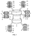
- a three dimensional (3D) cylindrical antenna 10 embodying certain features of the invention.
- the 3D antenna 10 is composed of six individual antenna coils 12,14,16,18, 20 and 22.
- the antenna coils are arranged in a nested relationship such that the antenna coils 12 and 14 which are designated horizontal middle antenna coils are nested within each other.
- the other antenna coils 16, 18, 20 and 22 are then nested within the horizontal middle antenna coils 12 and 14.
- the antenna coils 16 and 20 each have an upper portion (16a, 20a) and a lower portion (16b, 20b), the coils of which are wound about a horizontal axis to provide horizontal magnetic fields with different directions of flux as shown by the arrows 24, 26, 28 and 30, More specifically, the upper portion 16a of the antenna coil 16 provides a magnetic field which is directed horizontally from left to right (arrow 24) as shown in Fig. 1 , while the upper portion 20a of antenna coil 20 has a magnetic field (arrow 30) which is horizontal and at 90 ° to the direction of the magnetic field of the upper portion 16a of the antenna coil 16.
- the lower portion 16b of antenna coil 16 is wound such that it provides a horizontal magnetic field (arrow 26) which is phase shifted 180° from the magnetic field (arrow 24) of the upper portion 16a.
- the lower portion 20b of the antenna coil 20 is wound such as to provide a magnetic field (arrow 30) which is 90° phase shifted from the magnetic field (arrow 26) ofthe lower portion 16b of the antenna coil 16 and is also 180° phase shifted from the magnetic field (arrow 28) of the upper portion of the antenna coil 20.
- Each of the horizontal middle antenna coils 12, 14 has three portions, an upper portion (12a, 14a) a lower portion (12b, 14b) and a middle portion (12c, 14c), each of which is wound about a horizontal axis to provide a horizontal magnetic field in the direction shown in Fig. 1 . More specifically, the coils 12a and 12b of the upper and lower portions of the antenna coil 12 are wound so that the magnetic fields (arrows 32 and 34) are in the same direction and the middle portion 12c of the antenna coil 12 is wound such that its magnetic field (arrow 36) is 180 ° phase shifted from the upper and lower portions.
- the coils of the upper and lower portions 14a, 14b of the horizontal middle antenna 14 are wound such as to provide horizontal magnetic fields (arrows 38, 40) which are phase shifted 90° from the magnetic fields (arrows 32, 34) of the upper and lower portions 12a, 12b of the horizontal middle antenna 12 with the upper and lower portions 14a, 14b of the horizontal middle antenna 14 being oriented in the same direction and the middle portion 14c having a phase shift of 180° (arrow 42).
- the antenna coil 18 which is designated a vertical middle antenna has three coil portions, an upper, a lower and a middle coil portion (18a, 18b, 18c), each of which is wound around a vertical axis to provide vertical a magnetic field with the magnetic fields (arrows 44, 46) ofthe upper and lowerportions 18a and 18b being in the same direction and the magnetic field (arrow 48) ofthe middle portion 18c being phase shifted 180°.
- the antenna coil 22 which is designated as a vertical upper and lower antenna has two coils 22a and 22b which are wound about a vertical axis to provide opposing vertical magnetic fields as shown by the arrows 50 and 52.
- the upper and lower portions 16a, 16b of the antenna coil 16, the upper and lower portions 20a, 20b of the antenna coil 20, the upper and lower portions 12a, 12h of the antenna coil 12, the upper and lower portions 14a, 14b of the antenna coil 14 and the upper and lower portions 18a, 18b of the antenna coil 18 provide a noise compensation function. More specifically, the fields generated by these coils cooperate to reduce the emission of radiation from the 3D antenna 10 to comply with applicable government regulations and also act to minimize noise within the antenna 10 from external source.
- the middle portion 12 of the antenna coil 12, the middle portion 14c of the antenna coil 14, the middle portion 18c of the antenna coil 18 and the upper and lower portions 22a, 22b of the antenna coil 22 function to define a cylindrical reading portion to interrogate and read the identification codes of the transponders associated with items to be identified, as will be described in more detail below.
- the 3D antenna 10 has a reading portion bounded on the top and bottom by noise compensation portions.
- the turns 54 of the each of coils 12, 14, 16, 18, 20 and 22 have unequal spacing to provide a homogenous reading field. More specifically, the distance between the turns 54 increase when approaching the axis 56 of the coil. If the spacing were equal then the magnetic field would increase from outside to inside resulting in a non-homogenous magnetic field.
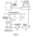
- FIG. 3 A block diagram of an embodiment ofthe invention for identifying items, such as gannents in slings 58 being transported by a conveyor system 60 is shown in Fig. 3 .
- Each of the garments has a transponder (not show in Fig. 3 ) which will be described in greater detail below.
- the sling 58 is conveyed into a position above a cylindrical 3D antenna, such as the antenna 10 of Fig. 1 , the sling 58 is lowered into the antenna 10.
- the antenna coils 12, 14, 16, 18, 20 and 22 ( Fig. 1 ) are then energized by a reader 62 which may be a Datamars D1 via an antenna muliiplex unit 64. This causes the antenna coils 12, 14, 16, 18, 20 and 22 ( Fig.
- Suitable means such as a computer 66, is provided to control the interrogaiion and reading of the transponders and also to control the conveyor system through a suitable controller 68, such as a Programmed Logic Control unit (PLC).
- PLC Programmed Logic Control unit
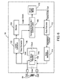
- FIG. 4 A more detailed block diagram of the reader 62 is shown in Fig. 4 .
- Each of the antenna coils 12, 14,16, 18, 20 and 22 is connected to the multiplexer 64 which, in turn, is connected to a receiver/transmitter 70 via an amplifier 72.
- the antenna coils 12, 14, 16, 18, 20 and 22 are energized sequentially causing the transponders (not shown) to generate return signals.
- the received return signals from the transponders are then sent to a digital processor 74 to identity the transponder.
- the signals received from the antenna coils 12, 14, 16, 18, 20 and 22 include both noise and the actual signal.
- An active noise cancellation unit 76 is used to remove noise.
- the active noise cancellation unit 76 provides signals similar to the reading signals received from the antenna coils 12, 14, 16, 18, 20 and 22 but based only on noise in the system. Essentially, the active noise cancellation unit 76 creates a small transmission system inside of the reader 62 which creates the same transmission situation as to the actual system but without any signals received from the transponders. in the digital processing unit 74, the noise cancellation signal is subtracted from the received signals so that the signal processed by the digital processing 74 unit is only the actual read signals received from the transponders.
- the digital processing unit 74 is controlled by an on board microprocessor. Alternatively, the digital processing unit may be controlled by an external computer.
- a power supply 80 is provided to supply power to the reader 64.
- the antennas coils 12, 14, 16, 18, 20 and 22 work sequentially under the control ofthe multiplexer 64 thereby providing a sequential reading field which results in a fractioning of the reading field.
- the coils 12, 14, 16, 18, 20 and 22 of the antenna 10 have a low Q (quality factor).
- the signals transmitted from the reader 62 to the transponders are modulated ASK (Amplitude Shift Keying) signals. If the modulation transition from 100% to 0% (OFF) or 0% to 100% (ON) is imperfect, the reader 64 is not able to transmit correct information to the transponders. Using lower Q antennas accelerates the transition from Off to On and vice versa. Thereby enhancing the accuracy of the reading.
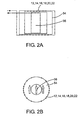
- Figs. 5A and 5B are cross sectional elevation and cross sectional plan views, respectively, of a transponder 82, such as a Datamars T-BT9200, illustrating certain features ofthe present invention.
- the transponder 82 includes a coil 84 mounted on a substrate 86 with spacers 88 so as to enable encapsulating material 90 to completely encircle the coil 84 therebyproviding protection and a rugged construction which enables the transponder to withstand severe environmental conditions, such as the repeated temperature changes which might be encountered when the transponder is embedded in clothing subjected to multiple washings.
- the coil 84 is connected via a printed circuit board 92 to an integrated circuit chip 94.
- the transponder 82 includes a suitable housing 98 which may be made ofPPS plastic, for example.
- the construction ofthe transponder enables the transponder to be minimized in size.
- the thickness 98 of the transponder may be less than 3mm and the diameter 100 may be less than 22 mm.
- Fig. 6 is a detailed block diagram of the integrated circuit chip 94
- the signals transmitted by the 3D antenna are received by the coil 84 which is in resonance with a capacitor Cres.
- a capacitor Csup provides a DC voltage or voltages for operating the remainder of the circuitry through a full wave rectifier 102.
- the signals received from the coil 84 also are sent to a clock extractor 104 and then to a divider 106 to provide a clock signal for sequencing operations in the reader. Data contained in the signal received from the reader is extracted from a data extractor 106 and sent to a command decoder/logic control circuit 108.
- the command decoder/control logic circuit 108 interrogates a ROM 110 which contains an identification code for the transponder 82 being interrogated.
- the information from the ROM 110 is then coded by a data encoder 112, modulated by a data modulator 114 and then transmitted to the reader via the coil 84. It should be noted that locating the capacitor Cres in the integrated circuit 94 enables minimization of the transponder 82.
- the reader 64 provides control logic data logic and software providing an "anti-collision protocol.
- the communication protocol employed must enable the simultaneous reception of a "0” and a "1" from different transponders 82 to be recognized and resolved. Further, the reception of the "0” or the "1” must still be reliably achieved if a number of transponders 82 simultaneously transmit that same value.
- the protocol employed in the present system is based upon binary coding having the characteristics of the known Manchester II Code.
- Manchester II code the values "0" and "1" are distinguished not by different high and low logic levels but by the position of a high logic level in either the first half or the second half of a defined bit period. There is, therefore, a logic transition at the middle of each bit period, the binary value of data being represented by the direction of the transition.
- the reader 62 alternately echoes back to the transponders 82 a binary value corresponding to the value last received.
- the reader 62 echoes back to the transponders 82 only a predetermined single value from the transponder(s) 82.
- the transponder(s) 82 which did not transmit that value then cease transmission. This process continues until one of the transponders 82 has transmitted and has echoed back to the reader 62 bit by bit all of its message.
- That transponder 82 then ceases transmission (i.e., is placed in a quiet mode) and the remaining transponders 82 recommence operation until by repetition of the process all of the individual transponder messages have been transmitted and echoed back.
- the reader 62 can specify the code number of a transponder 82 and put it in the quiet mode immediately. As there is more than one antenna in the reading system, one transponder 82 could be read more than one time with several different antennas (maximum of six times with six different antennas). If a transponder 82 is read one time, it is useless that that transponder be read again.
- the reader 62 puts the transponder 82 in the quiet mode before starting readings with the next antenna.
- the time needed for reading is less than reading a transponder several times with several different antennas because the time needed for putting the transponders in a quiet mode is much less than the time for reading them.
- the three dimensional antenna employed may have either have the cylindrical shape shown in Figs. 1 and 3 or any other suitable shape, such as cubical.
- a flat bed conveyor 116 transports a box 118 containing a plurality of item 120.
- the items 120 maybe placed in any position in the box 118.
- the system employs a cubic shape antenna 122 which is positioned above the conveyor 116 which has a vertically movable portion 124.
- the movable conveyor portion 124 When, as shown in Fig. 7B , the box 118 is positioned directly under the antenna 122, the movable conveyor portion 124 is raised such that the box 118 is moved into the antenna 122 such that it is completely encompassed by the antenna 122. In this position, all of the items 120 inside the box 118 are surrounded by the antenna 122 thus enabling the items 120 (i.e., their associated transponders) to be interrogated and read.
- the movable conveyor portion 124 is then moved downwardly.
- the box 118 then continues along the conveyor 116.
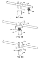
- FIG. 8A there is shown an embodiment of the invention employed in an industrial laundry where a bag 126 containing textile items 128, is transported with a conveyor 130 to one or more, processing station, such as washing machines (not shown).
- One part 132 of the conveyor 130 is mounted on a vertically movable mechanism 134 to enable it to be lifted up and down.
- An antenna 136 is positioned below the movable part 132 of the conveyor 130.
- the moveable part 132 of the conveyor is moved downwardly so that the bag 128 is placed inside the antenna 136.
- the movable part 132 of the conveyor has reached its lowermost position and the bag 126 is completely surrounded by the antenna 136. This enables the reading of all of the item 126 inside of the bag 126.
- the conveyor portion 132 is then lifted back to its original position ( Fig. 8D ) and the bag 126 continues its travel on the conveyor 130 ( Fig. 8E ).
Landscapes
- Engineering & Computer Science (AREA)
- Physics & Mathematics (AREA)
- General Physics & Mathematics (AREA)
- Theoretical Computer Science (AREA)
- Toxicology (AREA)
- Health & Medical Sciences (AREA)
- Artificial Intelligence (AREA)
- Computer Vision & Pattern Recognition (AREA)
- Computer Networks & Wireless Communication (AREA)
- Microelectronics & Electronic Packaging (AREA)
- Computer Hardware Design (AREA)
- Electromagnetism (AREA)
- General Health & Medical Sciences (AREA)
- Near-Field Transmission Systems (AREA)
- Control Of Conveyors (AREA)
- Discharge Of Articles From Conveyors (AREA)
Claims (12)
- Vorrichtung zur Identifizierung einer Vielzahl von Gegenständen, von denen ein jeder einen Hochfrequenztransponder (82) aufweist, wobei die Vorrichtung aufweist:eine Fördereinrichtung (60; 116; 130) für das Transportieren der Gegenstände;eine dreidimensionale Hochfrequenzantenne (10; 122; 136), die auf einer Seite der Fördereinrichtung positioniert ist, wobei die Fördereinrichtung einen beweglichen Teil (58; 124; 132) für das Bewegen der Gegenstände in die Antenne hinein und aus dieser heraus aufweist, so dass die Gegenstände, wenn sie sich in der Antenne befinden, vollständig durch die Antenne umgeben werden; undein Lesegerät (62) für das Senden von Abfragesignalen zu den Transpondern mittels der Antenne und für das Lesen der Identifizierungsinformation von den Transpondern.
- Vorrichtung nach Anspruch 1, bei der die dreidimensionale Antenne eine Vielzahl von Spulen aufweist, die in einer dreidimensionalen Anordnung derart montiert sind, dass ein dreidimensionales Lesefeld bereitgestellt wird, in dem alle Transponder im Lesefeld abgefragt werden können.
- Vorrichtung nach Anspruch 2, bei der die Spulen, die das Lesefeld definieren, sequentiell abgefragt werden, bis alle Transponder identifiziert sind.
- Vorrichtung nach Anspruch 3, bei der, nachdem ein Transponder identifiziert ist, er in eine geräuscharme Betriebsart gebracht wird, um zu verhindern, dass der gleiche Transponder auf Abfragesignale von der Antenne anspricht.
- Vorrichtung nach Anspruch 2, bei der die Antenne mindestens zwei Spulen aufweist, die eine Phasenverschiebung von 180° zwischen ihren Magnetfeldern aufweisen, wobei die Spulen in einer derartigen Weise strukturiert und angeordnet sind, dass ein unerwünschtes elektromagnetisches Rauschen verringert wird, das das Lesefeldes beeinflusst.
- Vorrichtung nach Anspruch 2, bei der die Antenne mindestens zwei Spulen aufweist, die eine Phasenverschiebung von 180° zwischen ihren Magnetfeldern aufweisen, wobei die Spulen in einer derartigen Weise strukturiert und angeordnet sind, dass eine elektromagnetische Strahlung minimiert wird, die außerhalb der Antenne emittiert wird.
- Vorrichtung nach Anspruch 2, bei der die Antenne Kompensationsspulen mit Magnetfeldern mit einer Phasenverschiebung von 180° umfasst, die an den externen Grenzen des Lesebereiches so positioniert sind, dass die Magnetfelder außerhalb des Lesebereiches unzureichend sind, um Transponder außerhalb des Lesefeldes abzufragen und zu lesen.
- Vorrichtung nach Anspruch 1, bei der der Hochfrequenztransponder (82) aufweist:ein Gehäuse (98);ein Substrat (86) innerhalb des Gehäuses;eine Leiterplatte (92), die auf dem Substrat montiert ist;eine Spule (84), die auf dem Substrat so montiert ist, dass sie davon beabstandet ist; undein Einkapselungsmittel (90), das das Substrat, die Leiterplatte, den integrierten Schaltchip und die Spule einkapselt, wobei der Abstand der Spule vom Substrat ermöglicht, dass das Einkapselungsmittel vollständig die Spule umgibt.
- Vorrichtung nach Anspruch 8, bei der die Spule vom Substrat durch eine Vielzahl von Distanzelementen beabstandet ist, die sich zwischen dem Substrat und der Spule erstrecken.
- Vorrichtung nach Anspruch 1, bei der die dreidimensionale Hochfrequenzantenne aufweist:eine Vielzahl von zylindrischen Antennenspulen (12, 14, 16, 18, 20, 22), die miteinander in einer ineinandergeschachtelten Beziehung angeordnet sind, wobei einige der Spulen (12, 14, 16, 20) so gewickelt sind, dass eine horizontale Magnetfeldphasenverschiebung bei 180° und 90° erzeugt werden kann, und wobei die anderen der Spulen (18, 22) so gewickelt sind, dass vertikale Magnetfelder mit Phasenverschiebungen von 180° entwickelt werden können;wobei die Vielzahl der zylindrischen Antennenspulen außerdem so angeordnet ist, dass ein dreidimensionaler Lesebereich entwickelt wird, und dass Rauschkompensationsbereiche an entgegengesetzten Enden des Lesebereiches entwickelt werden.
- Vorrichtung nach Anspruch 10, bei der eine jede Spule Windungen mit einem ungleichen Abstand dazwischen aufweist, so dass das durch die Spule entwickelte Magnetfeld homogen ist.
- Vorrichtung nach Anspruch 10, bei der die Spulen um die jeweiligen Achsen gewickelt sind und der Abstand zwischen den Windungen der Spulen größer wird, wenn sie sich der jeweiligen Achse nähern.
Applications Claiming Priority (4)
| Application Number | Priority Date | Filing Date | Title |
|---|---|---|---|
| US39126502P | 2002-06-24 | 2002-06-24 | |
| US39140202P | 2002-06-24 | 2002-06-24 | |
| US391265P | 2002-06-24 | ||
| US391402P | 2002-06-24 |
Publications (3)
| Publication Number | Publication Date |
|---|---|
| EP1376446A2 EP1376446A2 (de) | 2004-01-02 |
| EP1376446A3 EP1376446A3 (de) | 2004-04-14 |
| EP1376446B1 true EP1376446B1 (de) | 2010-01-13 |
Family
ID=29718541
Family Applications (1)
| Application Number | Title | Priority Date | Filing Date |
|---|---|---|---|
| EP03253967A Expired - Lifetime EP1376446B1 (de) | 2002-06-24 | 2003-06-24 | Verfahren und Vorrichtung zur Identifizierung von mehreren Gegenständen auf einem Transportband mit Transpondern |
Country Status (4)
| Country | Link |
|---|---|
| US (2) | US7198193B2 (de) |
| EP (1) | EP1376446B1 (de) |
| AT (1) | ATE455335T1 (de) |
| DE (1) | DE60330932D1 (de) |
Families Citing this family (12)
| Publication number | Priority date | Publication date | Assignee | Title |
|---|---|---|---|---|
| US7198193B2 (en) * | 2002-06-24 | 2007-04-03 | Datamars S.A. | Method and apparatus for identifying a set of multiple items on conveyor system with multiread transponders |
| USD615071S1 (en) * | 2003-09-09 | 2010-05-04 | Qinetiq Limited | Deployable sensor module |
| GB0321041D0 (en) * | 2003-09-09 | 2004-02-04 | Qinetiq Ltd | Sensor apparatus and system |
| DE102004054341A1 (de) * | 2004-11-09 | 2006-05-24 | ASTRA Gesellschaft für Asset Management mbH & Co. KG | Lesegerät zum berührungslosen Lesen von Transponderdaten |
| US7411508B2 (en) * | 2005-06-17 | 2008-08-12 | Perkinemer Las, Inc. | Methods and systems for locating and identifying labware using radio-frequency identification tags |
| WO2007061421A1 (en) * | 2005-11-28 | 2007-05-31 | Howard Jenkins | Scanning identification device |
| US7760093B2 (en) * | 2006-07-26 | 2010-07-20 | Broadcom Corporation | RFID interface and applications thereof |
| US20080115541A1 (en) * | 2006-11-22 | 2008-05-22 | Aldridge Jeffrey L | Garment Processing Personnel Safety Apparatus |
| US7876220B2 (en) * | 2006-11-22 | 2011-01-25 | Cintas Corporation | Garment tracking and processing system |
| US20080116274A1 (en) * | 2006-11-22 | 2008-05-22 | Aldridge Jeffrey L | Garment RFID Private Protocol Apparatus |
| EP2248074B1 (de) * | 2008-02-26 | 2016-05-25 | Avery Dennison Corporation | Rfid-etikett für direkten und indirekten lebensmittelkontakt |
| JP5482964B2 (ja) * | 2011-04-13 | 2014-05-07 | 株式会社村田製作所 | 無線icデバイス及び無線通信端末 |
Family Cites Families (14)
| Publication number | Priority date | Publication date | Assignee | Title |
|---|---|---|---|---|
| US3832530A (en) | 1972-01-04 | 1974-08-27 | Westinghouse Electric Corp | Object identifying apparatus |
| US4594550A (en) * | 1982-09-07 | 1986-06-10 | Utsunomiya University | Method of scanning specifying magnetic field for nuclear magnetic resonance imaging |
| US4623877A (en) * | 1983-06-30 | 1986-11-18 | Knogo Corporation | Method and apparatus for detection of targets in an interrogation zone |
| US5565846A (en) * | 1994-04-25 | 1996-10-15 | Indala Corporation | Reader system for waste bin pickup vehicles |
| US5648765A (en) * | 1995-03-08 | 1997-07-15 | Cresap; Michael S. | Tag tansponder system and method to identify items for purposes such as locating, identifying, counting, inventorying, or the like |
| US6218942B1 (en) * | 1995-10-11 | 2001-04-17 | Motorola, Inc. | Radio frequency identification tag exciter/reader |
| JPH11166963A (ja) * | 1997-12-04 | 1999-06-22 | Kyodo Kumiai Joint Labo Sendai | 磁界方向検出方法 |
| US6147604A (en) * | 1998-10-15 | 2000-11-14 | Intermec Ip Corporation | Wireless memory device |
| US6201474B1 (en) * | 1998-10-21 | 2001-03-13 | Intermec Ip Corp. | Magnetic tape storage media having RFID transponders |
| DE29905841U1 (de) | 1999-03-30 | 1999-06-24 | MOBA - Mobile Automation GmbH, 65604 Elz | Müllsackidentifikationssystem |
| CA2425597A1 (en) | 2000-10-10 | 2002-04-18 | Escort Memory Systems | Modular rfid antenna system |
| US6696954B2 (en) * | 2000-10-16 | 2004-02-24 | Amerasia International Technology, Inc. | Antenna array for smart RFID tags |
| US7198193B2 (en) * | 2002-06-24 | 2007-04-03 | Datamars S.A. | Method and apparatus for identifying a set of multiple items on conveyor system with multiread transponders |
| US20080117027A1 (en) * | 2006-11-16 | 2008-05-22 | Zih Corporation | Systems, methods, and associated rfid antennas for processing a plurality of transponders |
-
2003
- 2003-06-23 US US10/601,903 patent/US7198193B2/en not_active Expired - Fee Related
- 2003-06-24 AT AT03253967T patent/ATE455335T1/de not_active IP Right Cessation
- 2003-06-24 EP EP03253967A patent/EP1376446B1/de not_active Expired - Lifetime
- 2003-06-24 DE DE60330932T patent/DE60330932D1/de not_active Expired - Fee Related
-
2007
- 2007-03-30 US US11/731,053 patent/US7648069B2/en not_active Expired - Fee Related
Also Published As
| Publication number | Publication date |
|---|---|
| US7198193B2 (en) | 2007-04-03 |
| DE60330932D1 (de) | 2010-03-04 |
| EP1376446A3 (de) | 2004-04-14 |
| US20070182561A1 (en) | 2007-08-09 |
| US7648069B2 (en) | 2010-01-19 |
| ATE455335T1 (de) | 2010-01-15 |
| EP1376446A2 (de) | 2004-01-02 |
| US20040046022A1 (en) | 2004-03-11 |
Similar Documents
| Publication | Publication Date | Title |
|---|---|---|
| US7648069B2 (en) | Method and apparatus for identifying a set of multiple items on a conveyor system with multiread transponders | |
| AU665975B2 (en) | Transponder system | |
| US11030429B2 (en) | Multipurpose RFID transponder and a system for reading it | |
| AU2010315240B2 (en) | Signal cancelling transmit/receive multi-loop antenna for a radio frequency identification reader | |
| EP0918308A2 (de) | Artikelsortiersystem | |
| US6094173A (en) | Method and apparatus for detecting an RFID tag signal | |
| US7196613B2 (en) | System for multi-standard RFID tags | |
| US5099226A (en) | Intelligent security system | |
| US8810376B1 (en) | Encoding RFID tags of grouped items | |
| US10671822B1 (en) | Multipurpose RFID transponder and a system for reading it | |
| US20100237996A1 (en) | Reader for rfid transponders and corresponding method | |
| CN1246947A (zh) | 读取多个射频标识标签的防冲突协议 | |
| US11790191B2 (en) | Multipurpose RFID transponder and a system for reading it | |
| JP6470168B2 (ja) | 読取制御装置、読取制御方法、読取制御プログラム | |
| WO1986002186A1 (en) | Identification system | |
| EP0496609A1 (de) | Abfragestation zur Identifikation von Gegenständen | |
| JP2005108112A (ja) | タグ情報読取法及び読取装置 | |
| HU222800B1 (hu) | Eljárás válaszjeladók egyidejű vezérlésére és programozására és eszköz az eljárás megvalósítására | |
| KR101026438B1 (ko) | 가상 공간관리 방법 및 시스템과 가상 공간 이동장치 및이를 위한 기록매체 | |
| EP1388216B1 (de) | Kommunikationsgerät mit spulenkonfiguration zur kommunikation mit stationären datenträgern | |
| GB2568915A (en) | Reshaping interrogation range | |
| Chaffai et al. | Exploring Dual-Frequency Implementation for Semi-Passive RFID Tags | |
| JP2004244140A (ja) | 搬送ライン用アンテナ装置 | |
| CN220604030U (zh) | 一种可进行二次确认的rfid标签读取装置 | |
| CN210199773U (zh) | 一种物料自动识别装置 |
Legal Events
| Date | Code | Title | Description |
|---|---|---|---|
| PUAI | Public reference made under article 153(3) epc to a published international application that has entered the european phase |
Free format text: ORIGINAL CODE: 0009012 |
|
| 17P | Request for examination filed |
Effective date: 20030707 |
|
| AK | Designated contracting states |
Kind code of ref document: A2 Designated state(s): AT BE BG CH CY CZ DE DK EE ES FI FR GB GR HU IE IT LI LU MC NL PT RO SE SI SK TR |
|
| AX | Request for extension of the european patent |
Extension state: AL LT LV MK |
|
| RIN1 | Information on inventor provided before grant (corrected) |
Inventor name: DOTTI, ROBERTO Inventor name: HASSAN-ZADE, PARVIS Inventor name: ISHII, TAKAMASA |
|
| PUAL | Search report despatched |
Free format text: ORIGINAL CODE: 0009013 |
|
| AK | Designated contracting states |
Kind code of ref document: A3 Designated state(s): AT BE BG CH CY CZ DE DK EE ES FI FR GB GR HU IE IT LI LU MC NL PT RO SE SI SK TR |
|
| AX | Request for extension of the european patent |
Extension state: AL LT LV MK |
|
| AKX | Designation fees paid |
Designated state(s): AT BE BG CH CY CZ DE DK EE ES FI FR GB GR HU IE IT LI LU MC NL PT RO SE SI SK TR |
|
| 17Q | First examination report despatched |
Effective date: 20081219 |
|
| GRAP | Despatch of communication of intention to grant a patent |
Free format text: ORIGINAL CODE: EPIDOSNIGR1 |
|
| RIC1 | Information provided on ipc code assigned before grant |
Ipc: G06K 7/08 20060101AFI20090708BHEP Ipc: H01Q 1/22 20060101ALI20090708BHEP Ipc: G06K 7/10 20060101ALI20090708BHEP |
|
| GRAS | Grant fee paid |
Free format text: ORIGINAL CODE: EPIDOSNIGR3 |
|
| GRAA | (expected) grant |
Free format text: ORIGINAL CODE: 0009210 |
|
| AK | Designated contracting states |
Kind code of ref document: B1 Designated state(s): AT BE BG CH CY CZ DE DK EE ES FI FR GB GR HU IE IT LI LU MC NL PT RO SE SI SK TR |
|
| REG | Reference to a national code |
Ref country code: GB Ref legal event code: FG4D |
|
| REG | Reference to a national code |
Ref country code: CH Ref legal event code: EP |
|
| REG | Reference to a national code |
Ref country code: IE Ref legal event code: FG4D |
|
| REF | Corresponds to: |
Ref document number: 60330932 Country of ref document: DE Date of ref document: 20100304 Kind code of ref document: P |
|
| REG | Reference to a national code |
Ref country code: NL Ref legal event code: VDEP Effective date: 20100113 |
|
| PG25 | Lapsed in a contracting state [announced via postgrant information from national office to epo] |
Ref country code: AT Free format text: LAPSE BECAUSE OF FAILURE TO SUBMIT A TRANSLATION OF THE DESCRIPTION OR TO PAY THE FEE WITHIN THE PRESCRIBED TIME-LIMIT Effective date: 20100113 |
|
| PG25 | Lapsed in a contracting state [announced via postgrant information from national office to epo] |
Ref country code: NL Free format text: LAPSE BECAUSE OF FAILURE TO SUBMIT A TRANSLATION OF THE DESCRIPTION OR TO PAY THE FEE WITHIN THE PRESCRIBED TIME-LIMIT Effective date: 20100113 Ref country code: ES Free format text: LAPSE BECAUSE OF FAILURE TO SUBMIT A TRANSLATION OF THE DESCRIPTION OR TO PAY THE FEE WITHIN THE PRESCRIBED TIME-LIMIT Effective date: 20100424 Ref country code: PT Free format text: LAPSE BECAUSE OF FAILURE TO SUBMIT A TRANSLATION OF THE DESCRIPTION OR TO PAY THE FEE WITHIN THE PRESCRIBED TIME-LIMIT Effective date: 20100513 |
|
| PG25 | Lapsed in a contracting state [announced via postgrant information from national office to epo] |
Ref country code: SI Free format text: LAPSE BECAUSE OF FAILURE TO SUBMIT A TRANSLATION OF THE DESCRIPTION OR TO PAY THE FEE WITHIN THE PRESCRIBED TIME-LIMIT Effective date: 20100113 Ref country code: FI Free format text: LAPSE BECAUSE OF FAILURE TO SUBMIT A TRANSLATION OF THE DESCRIPTION OR TO PAY THE FEE WITHIN THE PRESCRIBED TIME-LIMIT Effective date: 20100113 |
|
| PG25 | Lapsed in a contracting state [announced via postgrant information from national office to epo] |
Ref country code: GR Free format text: LAPSE BECAUSE OF FAILURE TO SUBMIT A TRANSLATION OF THE DESCRIPTION OR TO PAY THE FEE WITHIN THE PRESCRIBED TIME-LIMIT Effective date: 20100414 Ref country code: SE Free format text: LAPSE BECAUSE OF FAILURE TO SUBMIT A TRANSLATION OF THE DESCRIPTION OR TO PAY THE FEE WITHIN THE PRESCRIBED TIME-LIMIT Effective date: 20100113 Ref country code: RO Free format text: LAPSE BECAUSE OF FAILURE TO SUBMIT A TRANSLATION OF THE DESCRIPTION OR TO PAY THE FEE WITHIN THE PRESCRIBED TIME-LIMIT Effective date: 20100113 Ref country code: EE Free format text: LAPSE BECAUSE OF FAILURE TO SUBMIT A TRANSLATION OF THE DESCRIPTION OR TO PAY THE FEE WITHIN THE PRESCRIBED TIME-LIMIT Effective date: 20100113 Ref country code: CY Free format text: LAPSE BECAUSE OF FAILURE TO SUBMIT A TRANSLATION OF THE DESCRIPTION OR TO PAY THE FEE WITHIN THE PRESCRIBED TIME-LIMIT Effective date: 20100113 Ref country code: BE Free format text: LAPSE BECAUSE OF FAILURE TO SUBMIT A TRANSLATION OF THE DESCRIPTION OR TO PAY THE FEE WITHIN THE PRESCRIBED TIME-LIMIT Effective date: 20100113 |
|
| PGFP | Annual fee paid to national office [announced via postgrant information from national office to epo] |
Ref country code: CH Payment date: 20100916 Year of fee payment: 8 |
|
| PLBE | No opposition filed within time limit |
Free format text: ORIGINAL CODE: 0009261 |
|
| STAA | Information on the status of an ep patent application or granted ep patent |
Free format text: STATUS: NO OPPOSITION FILED WITHIN TIME LIMIT |
|
| PG25 | Lapsed in a contracting state [announced via postgrant information from national office to epo] |
Ref country code: BG Free format text: LAPSE BECAUSE OF FAILURE TO SUBMIT A TRANSLATION OF THE DESCRIPTION OR TO PAY THE FEE WITHIN THE PRESCRIBED TIME-LIMIT Effective date: 20100413 Ref country code: CZ Free format text: LAPSE BECAUSE OF FAILURE TO SUBMIT A TRANSLATION OF THE DESCRIPTION OR TO PAY THE FEE WITHIN THE PRESCRIBED TIME-LIMIT Effective date: 20100113 Ref country code: SK Free format text: LAPSE BECAUSE OF FAILURE TO SUBMIT A TRANSLATION OF THE DESCRIPTION OR TO PAY THE FEE WITHIN THE PRESCRIBED TIME-LIMIT Effective date: 20100113 |
|
| 26N | No opposition filed |
Effective date: 20101014 |
|
| PG25 | Lapsed in a contracting state [announced via postgrant information from national office to epo] |
Ref country code: DK Free format text: LAPSE BECAUSE OF FAILURE TO SUBMIT A TRANSLATION OF THE DESCRIPTION OR TO PAY THE FEE WITHIN THE PRESCRIBED TIME-LIMIT Effective date: 20100113 Ref country code: MC Free format text: LAPSE BECAUSE OF NON-PAYMENT OF DUE FEES Effective date: 20100630 |
|
| GBPC | Gb: european patent ceased through non-payment of renewal fee |
Effective date: 20100624 |
|
| REG | Reference to a national code |
Ref country code: FR Ref legal event code: ST Effective date: 20110228 |
|
| PG25 | Lapsed in a contracting state [announced via postgrant information from national office to epo] |
Ref country code: IT Free format text: LAPSE BECAUSE OF FAILURE TO SUBMIT A TRANSLATION OF THE DESCRIPTION OR TO PAY THE FEE WITHIN THE PRESCRIBED TIME-LIMIT Effective date: 20100113 |
|
| PG25 | Lapsed in a contracting state [announced via postgrant information from national office to epo] |
Ref country code: IE Free format text: LAPSE BECAUSE OF NON-PAYMENT OF DUE FEES Effective date: 20100624 Ref country code: DE Free format text: LAPSE BECAUSE OF NON-PAYMENT OF DUE FEES Effective date: 20110101 |
|
| PG25 | Lapsed in a contracting state [announced via postgrant information from national office to epo] |
Ref country code: FR Free format text: LAPSE BECAUSE OF NON-PAYMENT OF DUE FEES Effective date: 20100630 |
|
| PG25 | Lapsed in a contracting state [announced via postgrant information from national office to epo] |
Ref country code: GB Free format text: LAPSE BECAUSE OF NON-PAYMENT OF DUE FEES Effective date: 20100624 |
|
| REG | Reference to a national code |
Ref country code: CH Ref legal event code: PL |
|
| PG25 | Lapsed in a contracting state [announced via postgrant information from national office to epo] |
Ref country code: LI Free format text: LAPSE BECAUSE OF NON-PAYMENT OF DUE FEES Effective date: 20110630 Ref country code: CH Free format text: LAPSE BECAUSE OF NON-PAYMENT OF DUE FEES Effective date: 20110630 |
|
| PG25 | Lapsed in a contracting state [announced via postgrant information from national office to epo] |
Ref country code: LU Free format text: LAPSE BECAUSE OF NON-PAYMENT OF DUE FEES Effective date: 20100624 Ref country code: HU Free format text: LAPSE BECAUSE OF FAILURE TO SUBMIT A TRANSLATION OF THE DESCRIPTION OR TO PAY THE FEE WITHIN THE PRESCRIBED TIME-LIMIT Effective date: 20100714 |
|
| PG25 | Lapsed in a contracting state [announced via postgrant information from national office to epo] |
Ref country code: TR Free format text: LAPSE BECAUSE OF FAILURE TO SUBMIT A TRANSLATION OF THE DESCRIPTION OR TO PAY THE FEE WITHIN THE PRESCRIBED TIME-LIMIT Effective date: 20100113 |