EP1378720A2 - Vorrichtung und Verfahren zur Montage eines Wärmetauschers, insbesondere für Kraftfahrzeuge - Google Patents
Vorrichtung und Verfahren zur Montage eines Wärmetauschers, insbesondere für Kraftfahrzeuge Download PDFInfo
- Publication number
- EP1378720A2 EP1378720A2 EP03015017A EP03015017A EP1378720A2 EP 1378720 A2 EP1378720 A2 EP 1378720A2 EP 03015017 A EP03015017 A EP 03015017A EP 03015017 A EP03015017 A EP 03015017A EP 1378720 A2 EP1378720 A2 EP 1378720A2
- Authority
- EP
- European Patent Office
- Prior art keywords
- heat exchanger
- housing
- type
- adapter piece
- heat
- Prior art date
- Legal status (The legal status is an assumption and is not a legal conclusion. Google has not performed a legal analysis and makes no representation as to the accuracy of the status listed.)
- Withdrawn
Links
Images

Classifications
-
- F—MECHANICAL ENGINEERING; LIGHTING; HEATING; WEAPONS; BLASTING
- F28—HEAT EXCHANGE IN GENERAL
- F28F—DETAILS OF HEAT-EXCHANGE AND HEAT-TRANSFER APPARATUS, OF GENERAL APPLICATION
- F28F9/00—Casings; Header boxes; Auxiliary supports for elements; Auxiliary members within casings
- F28F9/001—Casings in the form of plate-like arrangements; Frames enclosing a heat exchange core
- F28F9/002—Casings in the form of plate-like arrangements; Frames enclosing a heat exchange core with fastening means for other structures
-
- B—PERFORMING OPERATIONS; TRANSPORTING
- B60—VEHICLES IN GENERAL
- B60K—ARRANGEMENT OR MOUNTING OF PROPULSION UNITS OR OF TRANSMISSIONS IN VEHICLES; ARRANGEMENT OR MOUNTING OF PLURAL DIVERSE PRIME-MOVERS IN VEHICLES; AUXILIARY DRIVES FOR VEHICLES; INSTRUMENTATION OR DASHBOARDS FOR VEHICLES; ARRANGEMENTS IN CONNECTION WITH COOLING, AIR INTAKE, GAS EXHAUST OR FUEL SUPPLY OF PROPULSION UNITS IN VEHICLES
- B60K11/00—Arrangement in connection with cooling of propulsion units
- B60K11/02—Arrangement in connection with cooling of propulsion units with liquid cooling
- B60K11/04—Arrangement or mounting of radiators, radiator shutters, or radiator blinds
Definitions
- the invention relates to heat exchangers, in particular for motor vehicles.
- It relates more particularly to an equipment and a process for mounting a heat exchanger in a housing, the housing being delimited by walls and being arranged to be crossed by an air flow.
- the enclosure walls help to define a conduit for air flow in the passenger compartment of the motor vehicle under the action of an air blower.
- radiator again called “air heater”
- air heater arranged to heat an air flow which is sent into the passenger compartment.
- the box When the motor vehicle is also equipped with the air conditioning option, the box also houses an evaporator, which is generally placed upstream of the radiator of heating in relation to the air flow direction.
- the housing is formed of two mutually assembled shells.
- the mounting of the heat exchanger which be a heating radiator or an evaporator air conditioning, is carried out from an opening in a enclosure wall to allow drawer mounting.
- Such a heat exchanger usually comprises a body, usually a bundle of tubes and fins, connected to the minus a manifold.
- the air flow scans the body of the exchanger to be heated or cooled depending on the nature of the heat exchanger heat.
- the heat exchanger Once installed in the housing, the heat exchanger must be traversed entirely by the air flow, without creating parasitic air leaks between the heat exchanger and the enclosure walls.
- heat exchangers also called “brazed exchangers" which are essentially obtained by brazing of aluminum or aluminum alloy components.
- heat exchangers usually include a bundle of flat tubes and corrugated spacers, one of which at least one end is connected to a collecting box, all the components being brazed during the same surgery.
- heat exchangers in which the tubes of the bundle are assembled to one or two manifolds by mechanical means.
- the beam is composed of tubes which pass through flat fins. It could be parallel tubes received in two manifolds or else still hairpin tubes whose ends are received in a single manifold.
- exchangers of the first type above have a larger footprint than heat exchangers of the second type (mechanical exchangers) in at least one dimension.
- the object of the invention is in particular to overcome the drawbacks supra.
- the invention provides equipment for mounting the type defined above, which includes an adapter piece arranged to be interposed between the heat exchanger and the walls of the housing to make up for a dimensional difference.
- the same box can receive either directly a first type heat exchanger, or indirectly a heat exchanger of a second type, the latter being provided with the adapter piece.
- the adapter piece comprises a frame of general rectangular shape with two side faces together by two crosspieces to delimit two open faces for the passage of the air flow through the heat exchanger.
- one of the faces lateral also called introduction face
- the other side face also called face of reception
- the aforementioned receiving face may include at least one opening for the passage of at least one end heat exchanger.
- this face of reception includes a series of aligned openings, arranged to receive the u-bends of pin tubes the heat exchanger.
- the mounting equipment advantageously comprises means for fixing of the heat exchanger on the adapter piece.
- the heat exchanger and the adapter piece form a whole, which can then be put in place in the housing.
- the invention in another aspect, relates to a method of mounting a heat exchanger in a housing delimited by walls that define an air passage, this process including the operation of interposing, in the event of need, an adapter part as defined above between the heat exchanger and the walls of the housing for make up for a dimensional deviation.
- operation c2) includes the installation of the adapter piece around the front heat exchanger installation of the assembly in the housing.
- operation c1) advantageously comprises the setting in place of the heat exchanger in a drawer assembly.
- operation c2) advantageously includes setting up place of the heat exchanger and the adapter according to a drawer assembly.
- FIG. 1 shows, in section transverse, a box 10, called distribution box, being part of a heater and / or air conditioning of a motor vehicle.
- This box is formed by the assembly of two housing parts, a part 12A and a part 12B, joined together by assembly joints 14 and 16, in a manner known per se.
- the two parts of the case are advantageously made by molding a material plastic.
- This case has a cross section of general shape rectangular bounded by an upper wall 18, a wall lower 19, a side wall 20 (left side of Figure 1) and a side wall 22 (right side of Figure 1).
- a heat exchanger 24 in the example a heating radiator.
- This radiator is intended to heat an air flow which is set in motion in the housing by a pulser (not shown) to send a flow heated air in the passenger compartment of the vehicle.
- This radiator comprises a body 26, for example a bundle of tubes and fins (not shown in detail), connected to two boxes manifolds: a manifold 28 located near the wall side 20 and a manifold 30 located on the side of the side wall 22.
- the manifold 30 is protrudes outside the wall and is provided with two tubing 32 and 34 used for the admission and evacuation of a heat transfer fluid, for example coolant of the vehicle.
- the heat exchanger 24 is assembled by a "mounting in drawer “in the direction of arrow F1.
- the side wall 22 has an opening of general shape rectangular (not shown) through which is introduced the heat exchanger by first entering the box collector 28.
- the box collector 28 is received in the side wall 20, while the manifold 30 protrudes outside the wall 22, as shown in Figure 1.
- Tubing 32 and 34 can then be connected to a fluid circulation circuit, in itself known manner.
- the heat exchanger 24 is advantageously obtained by assembly, in a single operation of aluminum components or alloys based aluminum. Generally, these are flat tubes between which are placed corrugated dividers forming fins heat exchange, the ends of the tubes being received in manifolds 28 and 30.
- the heat exchanger 24 thus constitutes an exchanger of a first type (exchanger soldered) which is received directly in the housing 10.
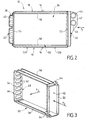
- the exchanger 36 can be assembled mechanically.
- the exchanger 36 includes a series of pin tubes 38, again called U-shaped tubes, each made up, in itself known, from two substantially parallel branches joined by a elbow 40.
- the ends of the branches are retained in a manifold 42 having two pipes 44 and 46 for the circulation of the heat transfer fluid.
- This fluid enters a compartment (not shown) of the manifold 42, runs from the first branches of the tubes 38 to the elbows 40 and then returns through the second branches of the tubes in U to reach another compartment (not shown) of the manifold 42.
- the elbows 40 are received in the side wall 20 of the housing.
- the heat exchanger is intended to be assembled by a drawer mounting.
- the manifold 42 protrudes outside the side wall 22 for allow the pipes 44 and 46 to be connected to the fluid circulation.
- the heat exchanger 36 which constitutes a exchanger of a second type (mechanical exchanger) is received in the housing 10 with the interposition of an adapter piece 50 which will now be described with reference to Figure 3.
- the adapter piece 50 includes a generally shaped frame rectangular having two lateral faces: a face 52, called “introduction face”, and an opposite face 54, called “face of reception ".
- the two side faces 52 and 54 are joined between them by two crosspieces: an upper crosspiece 56 and a lower cross member 58.
- the face 52 is a covered face delimiting an opening 60 of generally rectangular shape to allow the introduction, also by mounting in drawer, heat exchanger 36 (arrow F2).
- the receiving face 54 includes a series of openings aligned 62 arranged to receive the elbows 40 of the tubes of the bundle, in the example seven in number.
- the exchanger heat 36 is put in place, by a drawer assembly, in the adapter piece 50 in the direction of arrow F2.
- the latter is provided with two bosses 64 used for the mutual fixing of the heat exchanger 36 and the part adapter 50.
- This provides an assembly whose size corresponds substantially to the size of the heat exchanger 24 of Figure 1.
- the assembly can then be mounted in a drawer inside the case 10, under the same conditions as the heat exchanger 24.
- the same housing 10 can receive, as the case may be, either directly the heat exchanger 24 of Figure 1, or the heat exchanger 36 of Figure 2 with interposition of the adapter piece 50.
- the adapter piece 50 is advantageously produced by molding, preferably in one piece, of a plastic material.
- the adapter piece delimits two opposite open faces 66 and 68 which allow the passage of an air flow sweeping the heat exchanger bundle, as shown by arrow F3.
- the heat exchanger 36 could be mounted in the adapter piece 50 by one or other of the open faces 66 and 68.
- the invention finds particular application to exchangers heat for motor vehicles.
Landscapes
- Engineering & Computer Science (AREA)
- Mechanical Engineering (AREA)
- Chemical & Material Sciences (AREA)
- Combustion & Propulsion (AREA)
- Transportation (AREA)
- Physics & Mathematics (AREA)
- Thermal Sciences (AREA)
- General Engineering & Computer Science (AREA)
- Heat-Exchange Devices With Radiators And Conduit Assemblies (AREA)
- Air-Conditioning For Vehicles (AREA)
Applications Claiming Priority (2)
| Application Number | Priority Date | Filing Date | Title |
|---|---|---|---|
| FR0208388A FR2841974B1 (fr) | 2002-07-04 | 2002-07-04 | Equipement et procede de montage d'un echangeur de chaleur, notamment pour vehicule automobile |
| FR0208388 | 2002-07-04 |
Publications (2)
| Publication Number | Publication Date |
|---|---|
| EP1378720A2 true EP1378720A2 (de) | 2004-01-07 |
| EP1378720A3 EP1378720A3 (de) | 2004-05-19 |
Family
ID=29720092
Family Applications (1)
| Application Number | Title | Priority Date | Filing Date |
|---|---|---|---|
| EP03015017A Withdrawn EP1378720A3 (de) | 2002-07-04 | 2003-07-02 | Vorrichtung und Verfahren zur Montage eines Wärmetauschers, insbesondere für Kraftfahrzeuge |
Country Status (2)
| Country | Link |
|---|---|
| EP (1) | EP1378720A3 (de) |
| FR (1) | FR2841974B1 (de) |
Cited By (4)
| Publication number | Priority date | Publication date | Assignee | Title |
|---|---|---|---|---|
| WO2007017150A1 (de) * | 2005-08-06 | 2007-02-15 | Behr Gmbh & Co. Kg | Montageträgersystem |
| DE102005051661A1 (de) * | 2005-10-28 | 2007-05-16 | Hbpo Gmbh | Tragstruktur im Frontbereich eines Kraftfahrzeuges |
| EP2154464A3 (de) * | 2008-08-08 | 2013-08-28 | Behr GmbH & Co. KG | Wärmeübertrager und Verfahren zum Montieren eines Wärmeübertragers |
| CN107560206A (zh) * | 2017-10-25 | 2018-01-09 | 江苏科立德制冷设备有限公司 | 一种室外压缩冷凝机组 |
Family Cites Families (8)
| Publication number | Priority date | Publication date | Assignee | Title |
|---|---|---|---|---|
| DE2558895C3 (de) * | 1975-12-27 | 1986-07-10 | Süddeutsche Kühlerfabrik Julius Fr. Behr GmbH & Co KG, 7000 Stuttgart | Kühler für Fahrzeuge |
| US4137982A (en) * | 1977-08-08 | 1979-02-06 | Caterpillar Tractor Co. | Reinforced radiator mounting for heavy vehicles |
| JPH0689913B2 (ja) * | 1988-09-26 | 1994-11-14 | 三菱電機株式会社 | 熱交換器の保持装置 |
| FR2667935B1 (fr) * | 1990-10-12 | 1997-01-17 | Valeo Thermique Moteur Sa | Dispositif de fixation d'un echangeur de chaleur secondaire du type a serpentin sur un echangeur de chaleur principal et ensemble d'echangeurs ainsi obtenu |
| US5482113A (en) * | 1993-08-25 | 1996-01-09 | International Business Machines Corporation | Convertible heat exchanger for air or water cooling of electronic circuit components and the like |
| FR2724873A1 (fr) * | 1994-09-23 | 1996-03-29 | Socori Technologies | Procede de realisation d'une unite de chauffage pour climatiseur de vehicules automobiles, moyens en vue de sa mise en oeuvre, unite de chauffage et climatiseur obtenus a l'aide de ce procede. |
| US5570738A (en) * | 1995-11-13 | 1996-11-05 | Alliedsignal Inc. | Radiator assembly for use in a motor vehicle |
| FR2783765B1 (fr) * | 1998-09-25 | 2000-12-01 | Valeo Thermique Moteur Sa | Dispositif de fixation d'un equipement, notamment d'un echangeur de chaleur, sur un element de structure d'un vehicule automobile |
-
2002
- 2002-07-04 FR FR0208388A patent/FR2841974B1/fr not_active Expired - Fee Related
-
2003
- 2003-07-02 EP EP03015017A patent/EP1378720A3/de not_active Withdrawn
Cited By (4)
| Publication number | Priority date | Publication date | Assignee | Title |
|---|---|---|---|---|
| WO2007017150A1 (de) * | 2005-08-06 | 2007-02-15 | Behr Gmbh & Co. Kg | Montageträgersystem |
| DE102005051661A1 (de) * | 2005-10-28 | 2007-05-16 | Hbpo Gmbh | Tragstruktur im Frontbereich eines Kraftfahrzeuges |
| EP2154464A3 (de) * | 2008-08-08 | 2013-08-28 | Behr GmbH & Co. KG | Wärmeübertrager und Verfahren zum Montieren eines Wärmeübertragers |
| CN107560206A (zh) * | 2017-10-25 | 2018-01-09 | 江苏科立德制冷设备有限公司 | 一种室外压缩冷凝机组 |
Also Published As
| Publication number | Publication date |
|---|---|
| EP1378720A3 (de) | 2004-05-19 |
| FR2841974B1 (fr) | 2005-02-25 |
| FR2841974A1 (fr) | 2004-01-09 |
Similar Documents
| Publication | Publication Date | Title |
|---|---|---|
| EP2064506B1 (de) | Wärmetauscher, insbesondere ein systemluftkühler | |
| EP2402694B1 (de) | Kondensator insbesondere für ein klimaanlagensystem eines kraftfahrzeugs, und mit einem solchen kondensator ausgestatteter wärmetauscher | |
| EP1000308B1 (de) | Wärmetauscheranordnung für kraftfahrzeug | |
| EP1139054B2 (de) | Baueinheit aus Endkammer und Rohr für Wärmetauscher | |
| FR2789164A1 (fr) | Echangeur de chaleur ayant un reservoir formant collecteur | |
| FR2748316A1 (fr) | Echangeur de chaleur a boite collectrice tubulaire et patte de fixation | |
| FR2814230A1 (fr) | Module d'echange de chaleur pour vehicule automobile | |
| EP3077231B1 (de) | Anlage für ein kraftfahrzeug | |
| EP1089048A1 (de) | Vorrichtung zum Zusammenbau eines Einsatzes mit einem Wärmetauscher, insbesondere für Kraftfahrzeug | |
| EP1378720A2 (de) | Vorrichtung und Verfahren zur Montage eines Wärmetauschers, insbesondere für Kraftfahrzeuge | |
| WO1999030097A1 (fr) | Dispositif pour la fixation d'un conduit d'un premier echangeur de chaleur sur une boite a fluide d'un deuxieme echangeur de chaleur | |
| WO2011120972A1 (fr) | Echangeur de chaleur muni d'une bride de raccordement | |
| EP0838653A1 (de) | Wärmetauscher mit verbesserter Zufuhr für die Heizung, Lüftung und/ oder Klimaanlage, insbesondere für Kraftwagen | |
| FR2755222A1 (fr) | Echangeur de chaleur comportant une boite collectrice a deux compartiments adjacents | |
| FR2779221A1 (fr) | Ensemble d'echangeurs de chaleur destine a un vehicule automobile | |
| FR2892803A1 (fr) | Boite collectrice pour echangeur de chaleur, notamment pour evaporateur de climatisation, echangeur comportant une telle boite | |
| EP1676088A2 (de) | Schaltungselement für einen wärmetauscher und so erhaltener wärmetauscher | |
| EP0611940B1 (de) | Vorrichtung mit zwei Wärmetauschern und einem Ausdehnungsgefäss | |
| FR2849176A1 (fr) | Echangeur de chaleur muni d'un reservoir, en particulier pour vehicule automobile, et procede pour sa fabrication. | |
| FR2825459A1 (fr) | Module d'echange de chaleur comportant un reservoir fixe par l'intermediaire d'une piece de support, et piece de support | |
| WO2020043972A1 (fr) | Composant d'interface pour boîte collectrice d'échangeur thermique | |
| FR2931544A1 (fr) | Module d'echange de chaleur comprenant au moins deux echangeurs de chaleur parcourus par un meme fluide caloporteur. | |
| FR2786560A1 (fr) | Echangeur de chaleur brase a boites collectrices emboitees, en particulier pour vehicule automobile | |
| FR3060724A1 (fr) | Echangeur thermique, notamment evaporateur, muni d'un dispositif de raccordement pour l'introduction et l'extraction d'un fluide caloporteur. | |
| EP1509740B1 (de) | Verteilerwärmetauscher und verteilerkammer einfacher ausführung, insbesondere für kraftfahrzeug |
Legal Events
| Date | Code | Title | Description |
|---|---|---|---|
| PUAI | Public reference made under article 153(3) epc to a published international application that has entered the european phase |
Free format text: ORIGINAL CODE: 0009012 |
|
| AK | Designated contracting states |
Kind code of ref document: A2 Designated state(s): AT BE BG CH CY CZ DE DK EE ES FI FR GB GR HU IE IT LI LU MC NL PT RO SE SI SK TR |
|
| AX | Request for extension of the european patent |
Extension state: AL LT LV MK |
|
| PUAL | Search report despatched |
Free format text: ORIGINAL CODE: 0009013 |
|
| AK | Designated contracting states |
Kind code of ref document: A3 Designated state(s): AT BE BG CH CY CZ DE DK EE ES FI FR GB GR HU IE IT LI LU MC NL PT RO SE SI SK TR |
|
| AX | Request for extension of the european patent |
Extension state: AL LT LV MK |
|
| AKX | Designation fees paid | ||
| REG | Reference to a national code |
Ref country code: DE Ref legal event code: 8566 |
|
| STAA | Information on the status of an ep patent application or granted ep patent |
Free format text: STATUS: THE APPLICATION IS DEEMED TO BE WITHDRAWN |
|
| 18D | Application deemed to be withdrawn |
Effective date: 20070201 |