EP1378894A2 - Support d' enregistrement optique et procédé pour y enregistrer des données - Google Patents
Support d' enregistrement optique et procédé pour y enregistrer des données Download PDFInfo
- Publication number
- EP1378894A2 EP1378894A2 EP03014433A EP03014433A EP1378894A2 EP 1378894 A2 EP1378894 A2 EP 1378894A2 EP 03014433 A EP03014433 A EP 03014433A EP 03014433 A EP03014433 A EP 03014433A EP 1378894 A2 EP1378894 A2 EP 1378894A2
- Authority
- EP
- European Patent Office
- Prior art keywords
- recording layer
- recording
- layer
- dielectric layer
- recording medium
- Prior art date
- Legal status (The legal status is an assumption and is not a legal conclusion. Google has not performed a legal analysis and makes no representation as to the accuracy of the status listed.)
- Withdrawn
Links
Images


Classifications
-
- G—PHYSICS
- G11—INFORMATION STORAGE
- G11B—INFORMATION STORAGE BASED ON RELATIVE MOVEMENT BETWEEN RECORD CARRIER AND TRANSDUCER
- G11B7/00—Recording or reproducing by optical means, e.g. recording using a thermal beam of optical radiation by modifying optical properties or the physical structure, reproducing using an optical beam at lower power by sensing optical properties; Record carriers therefor
- G11B7/004—Recording, reproducing or erasing methods; Read, write or erase circuits therefor
- G11B7/0045—Recording
- G11B7/00455—Recording involving reflectivity, absorption or colour changes
-
- G—PHYSICS
- G11—INFORMATION STORAGE
- G11B—INFORMATION STORAGE BASED ON RELATIVE MOVEMENT BETWEEN RECORD CARRIER AND TRANSDUCER
- G11B7/00—Recording or reproducing by optical means, e.g. recording using a thermal beam of optical radiation by modifying optical properties or the physical structure, reproducing using an optical beam at lower power by sensing optical properties; Record carriers therefor
- G11B7/004—Recording, reproducing or erasing methods; Read, write or erase circuits therefor
- G11B7/0045—Recording
- G11B7/00456—Recording strategies, e.g. pulse sequences
-
- G—PHYSICS
- G11—INFORMATION STORAGE
- G11B—INFORMATION STORAGE BASED ON RELATIVE MOVEMENT BETWEEN RECORD CARRIER AND TRANSDUCER
- G11B7/00—Recording or reproducing by optical means, e.g. recording using a thermal beam of optical radiation by modifying optical properties or the physical structure, reproducing using an optical beam at lower power by sensing optical properties; Record carriers therefor
- G11B7/24—Record carriers characterised by shape, structure or physical properties, or by the selection of the material
- G11B7/2403—Layers; Shape, structure or physical properties thereof
- G11B7/24067—Combinations of two or more layers with specific interrelation
-
- G—PHYSICS
- G11—INFORMATION STORAGE
- G11B—INFORMATION STORAGE BASED ON RELATIVE MOVEMENT BETWEEN RECORD CARRIER AND TRANSDUCER
- G11B7/00—Recording or reproducing by optical means, e.g. recording using a thermal beam of optical radiation by modifying optical properties or the physical structure, reproducing using an optical beam at lower power by sensing optical properties; Record carriers therefor
- G11B7/24—Record carriers characterised by shape, structure or physical properties, or by the selection of the material
- G11B7/241—Record carriers characterised by shape, structure or physical properties, or by the selection of the material characterised by the selection of the material
- G11B7/242—Record carriers characterised by shape, structure or physical properties, or by the selection of the material characterised by the selection of the material of recording layers
- G11B7/243—Record carriers characterised by shape, structure or physical properties, or by the selection of the material characterised by the selection of the material of recording layers comprising inorganic materials only, e.g. ablative layers
-
- G—PHYSICS
- G11—INFORMATION STORAGE
- G11B—INFORMATION STORAGE BASED ON RELATIVE MOVEMENT BETWEEN RECORD CARRIER AND TRANSDUCER
- G11B7/00—Recording or reproducing by optical means, e.g. recording using a thermal beam of optical radiation by modifying optical properties or the physical structure, reproducing using an optical beam at lower power by sensing optical properties; Record carriers therefor
- G11B7/24—Record carriers characterised by shape, structure or physical properties, or by the selection of the material
- G11B7/241—Record carriers characterised by shape, structure or physical properties, or by the selection of the material characterised by the selection of the material
- G11B7/252—Record carriers characterised by shape, structure or physical properties, or by the selection of the material characterised by the selection of the material of layers other than recording layers
- G11B7/257—Record carriers characterised by shape, structure or physical properties, or by the selection of the material characterised by the selection of the material of layers other than recording layers of layers having properties involved in recording or reproduction, e.g. optical interference layers or sensitising layers or dielectric layers, which are protecting the recording layers
Definitions
- the present invention relates to an optical recording medium and a method for recording data in the optical recording medium and, particularly, to an optical recording medium capable of reproducing a signal having excellent signal characteristics and a method for recording data in the same so that a signal having excellent signal characteristics can be reproduced.
- optical recording media such as the CD, DVD and the like have been widely used as recording media for recording digital data.
- These optical recording media can be roughly classified into optical recording media such as the CD-ROM and the DVD-ROM that do not enable writing and rewriting of data (ROM type optical recording media), optical recording media such as the CD-R and DVD-R that enable writing but not rewriting of data (write-once type optical recording media), and optical recording media such as the CD-RW and DVD-RW that enable rewriting of data (data rewritable type optical recording media).
- phase change material is generally used as the material of the recording layer and data are recorded utilizing changes in an optical characteristic caused by phase change of the phase change material.
- an organic dye such as a cyanine dye, phthalocyanine dye or azo dye is generally used as the material of the recording layer and data are recorded utilizing changes in an optical characteristic caused by chemical change of the organic dye, which change may be accompanied by physical deformation.
- an optical recording material formed by laminating two recording layers is known as an example of an optical recording medium whose recording layer is formed of a material other than an organic dye.
- eutectic is formed of elements contained in the two recording layers when a laser beam is projected onto the optical recording medium, thereby forming a record mark and data are recorded therein as a difference between the optical property of the record mark and those of other regions.
- optical recording media other than the optical recording medium constituted so as to form a record mark of eutectic of elements contained in the two recording layers.
- the inventors of the present invention vigorously pursued a study for accomplishing the above objects and, as a result, made the discovery that when an optical recording medium including a first recording layer containing Si as a primary component, a second recording layer containing Cu as a primary component and a dielectric layer provided adjacent to the first recording layer or the second recording layer was irradiated with a laser beam having a wavelength ⁇ via an objective lens having a numerical aperture NA satisfying ⁇ / NA ⁇ 640 nm, Si contained in the first recording layer as a primary component and Cu contained in second recording layer as a primary component were mixed at a region irradiated with the laser beam, thereby forming a record mark whose reflection coefficient was different from those of other regions of the first recording layer and the second recording layer and a crystallized region whose reflection coefficient was different from those of other regions of the dielectric layer was formed at a region adjacent to the record mark, whereby the difference between the reflection coefficient of the region irradiated with the laser beam and those of other regions was increased
- an optical recording medium including a first recording layer containing one element selected from the group consisting of Ge, Sn, Mg, C, Al, Zn, In, Cu, Ti and Bi as a primary component
- a second recording layer containing one element from the group consisting of Cu, Si, Al, Zn and Ag and different from the element contained in the first recording layer as a primary component and a dielectric layer provided adjacent to the first recording layer or the second recording layer is irradiated with a laser beam having a wavelength ⁇ via an objective lens having a numerical aperture NA satisfying ⁇ / NA ⁇ 640 nm
- the element contained in the first recording layer as a primary component and the element contained in the second recording layer as a primary component were mixed at a region irradiated with the laser beam, thereby forming a record mark whose reflection coefficient was different from those of other regions of the first recording layer and the second recording layer and a crystallized region
- an optical recording medium including a single recording layer containing an inorganic element such as Sn, Ti or the like and a dielectric layer provided adjacent to the recording layer with a laser beam having a wavelength ⁇ via an objective lens having a numerical aperture NA satisfying ⁇ / NA ⁇ 640 nm
- a crystallized region whose reflection coefficient was different from those of other regions of the dielectric layer was formed at a region irradiated with the laser beam, whereby the difference between the reflection coefficient of the region irradiated with the laser beam and those of other regions was increased as a whole, the C/N ratio of a reproduced signal could be improved and jitter of the reproduced signal could be lowered.
- an optical recording medium comprising a substrate, at least one recording layer provided on the substrate and at least one dielectric layer provided adjacent to the at least one recording layer, the optical recording medium being constituted so that when it is irradiated with a laser beam having a wavelength ⁇ via an objective lens having a numerical aperture NA satisfying ⁇ / NA ⁇ 640 nm from the side opposite from the substrate, a record mark whose reflection coefficient is different from those of other regions of the at least one recording layer is formed in the at least one recording layer and at least a part of a region(s) of the at least one dielectric layer adjacent to the record mark is crystallized to form a crystallized region.
- the record mark is a region whose reflection coefficient has been changed as a result of irradiation with a laser beam.
- the at least one recording layer is constituted by a first recording layer containing one element selected from the group consisting of Si, Ge, Sn, Mg, C, Al, Zn, In, Cu, Ti and Bi as a primary component and a second recording layer provided in the vicinity of the first recording layer and containing one element selected from the group consisting of Cu, Si, Al, Zn and Ag and different from the element contained in the first recording layer as a primary component and when the laser beam is projected, the element contained in the first recording layer as a primary component and the element contained in the second recording layer as a primary component are mixed with each other, thereby forming a record mark.
- the statement that the first recording layer contains a certain element as a primary component means that the content of the element is maximum among the elements contained in the first recording layer
- the statement that the second recording layer contains a certain element as a primary component means that the content of the element is maximum among the elements contained in the second recording layer.
- the second recording layer it is not absolutely necessary for the second recording layer to be in contact with the first recording layer and it is sufficient for the second recording layer to be so located in the vicinity of the first recording layer as to enable formation of a mixed region including the primary component element of the first recording layer and the primary component element of the second recording layer when the region is irradiated with a laser beam.
- one or more other layers such as a dielectric layer may be interposed between the first recording layer and the second recording layer.
- the second recording layer is formed to be in contact with the first recording layer.
- the optical recording medium includes one or more recording layers containing the same element as a primary component as that contained in the first recording layer as a primary component or one or more recording layers containing the same element as a primary component as that contained in the second recording layer as a primary component.
- the optical recording medium when the optical recording medium is irradiated with a laser beam, since the element contained in the first recording layer as a primary component and the element contained in second recording layer as a primary component are mixed to each other, thereby forming a record mark whose reflection coefficient exhibiting with respect to a laser beam for reproducing data is different from those of other regions in the first recording layer and the second recording layer and at least a part of a region in contact with the record mark of the at least one dielectric layer is crystallized, thereby forming a crystallized region whose reflection coefficient exhibiting with respect to a laser beam for reproducing data is different from those of other regions in the at least one dielectric layer, the difference between the reflection coefficient exhibiting with respect to a laser beam for reproducing data of the region where the record mark is formed and those of other regions is considerably large and it is therefore possible to reproduce recorded data utilizing such large difference in the reflection coefficients, thereby obtaining a reproduced signal having an improved C/N ratio.
- a first dielectric layer is formed so as to be in contact with the first recording layer and a second dielectric layer is formed so as to be in contact with the second recording layer.
- the first recording layer contains an element selected from the group consisting of Si, Ge and Sn as a primary component.
- the second recording layer is added with an element selected from the group consisting of Cu, Al, Zn, Ag, Mg, Sn, Au, Ti and Pd and different from the element contained in the first recording layer as a primary component.
- the first recording layer contains an element selected from the group consisting of Si, Ge, Sn, Mg, In, Zn, Bi and Al as a primary component and the second recording layer contains Cu as a primary component.
- the first recording layer contains an element selected from the group consisting of Si, Ge, Sn, Mg and Al as a primary component.
- an element selected from the group consisting of Al, Si, Zn, Mg, Au, Sn, Ge, Ag, P, Cr, Fe and Ti is added to the second recording layer containing Cu as a primary component.
- an element selected from the group consisting of Al, Zn, Sn and Au is added to the second recording layer containing Cu as a primary component.
- the first recording layer contains an element selected from the group consisting of Si, Ge, C, Sn, Zn and Cu as a primary component and the second recording layer contains Al as a primary component.
- an element selected from the group consisting of Mg, Au, Ti and Cu is added to the second recording layer containing Al as a primary component.
- the first recording layer contains an element selected from the group consisting of Si, Ge, C and Al as a primary component and the second recording layer contains Zn as a primary component.
- an element selected from the group consisting of Mg, Cu and Al is added to the second recording layer containing Zn as a primary component.
- the first recording layer contains an element selected from the group consisting of Si, Ge and Sn as a primary component and the second recording layer contains Ag as a primary component.
- an element selected from the group consisting of Cu and Pd is added to the second recording layer containing Ag as a primary component.
- the first recording layer and the second recording layer are preferably formed so that a total thickness thereof is 2 nm to 40 nm, more preferably, 2 nm to 30 nm, most preferably, 2 nm to 15 nm.
- a dielectric material for forming the at least one dielectric layer is not particularly limited insofar as it is transparent and can be crystallized when irradiated with a laser beam and the at least one dielectric layer can be formed of a dielectric material containing oxide, sulfide, nitride or a combination thereof, for example, as a primary component.
- the at least one dielectric layer prefferably contains at least one dielectric material selected from the group consisting of Al 2 O 3 , AlN, ZnO, ZnS, GeN, GeCrN, CeO, SiO, SiO 2 , SiN and SiC as a primary component and it is more preferable for the at least one dielectric layer to contain ZnS• SiO 2 as a primary component.
- the optical recording medium further comprises a light transmission layer provided on a side opposite to the substrate with respect to the first recording layer and the second recording layer.
- the light transmission layer is formed so as to have a thickness of 10 ⁇ m to 300 ⁇ m.
- an optical recording medium further comprises a reflective layer provided between the substrate and the second dielectric layer.
- a method for recording data in an optical recording medium comprising the steps of irradiating an optical recording medium comprising a substrate, at least one recording layer provided on the substrate and at least one dielectric layer provided adjacent to at least one recording layer with a laser beam having a wavelength ⁇ via an objective lens having a numerical aperture NA satisfying ⁇ / NA ⁇ 640 nm from the side opposite from the substrate, forming a record mark in the at least one recording layer and crystallizing at least a part of a region(s) of the at least one dielectric layer adjacent to the record mark, thereby forming a crystallized region in the at least one dielectric layer.
- the method for optically recording data includes a step of projecting a laser beam having a wavelength of 450 nm or shorter onto the optical recording medium, thereby recording data in the first recording layer and the second recording layer.
- the power of the laser beam is modulated in accordance with a single pulse pattern when a recording linear velocity is equal to or higher than a predetermined recording linear velocity.
- the power of the laser beam is modulated in accordance with a single pulse pattern when a recording linear velocity is equal to or higher than a predetermined recording linear velocity, even in the case where a recording linear velocity is high, an amount of heat added to the first recording layer and the second recording layer from the laser beam becomes high. Therefore, since an amount of heat added to the at least one dielectric layer becomes high, a crystallize region can be formed in a desired manner at a region of the at least one dielectric layer adjacent to the record mark.
- Figure 1 is a schematic cross-sectional view showing the structure of an optical recording medium that is a preferred embodiment of the present invention.
- an optical recording medium 10 is constituted as a write-once type optical recording medium and includes a substrate 11, a reflective layer 12 formed on the surface of the substrate 11, a second dielectric layer 13 formed on the surface of the reflective layer 12, a second recording layer 32 formed on the surface of the second dielectric layer 13, a first recording layer 31 formed on the surface of the second recording layer 32, a first dielectric layer 15 formed on the surface of the first recording layer 31 and a light transmission layer 16 formed on the surface of the first dielectric layer 15.
- a center hole is formed at a center portion of the optical recording medium 10.
- a laser beam L10 is projected onto the surface of the light transmission layer 16, thereby recording data in the optical recording medium 10 or reproducing data from the optical recording medium 10.
- the substrate 11 serves as a support for ensuring mechanical strength required for the optical recording medium 10.
- the material used to form the substrate 11 is not particularly limited insofar as the substrate 11 can serve as the support of the optical recording medium 10.
- the substrate 11 can be formed of glass, ceramic, resin or the like.
- resin is preferably used for forming the substrate 11 since resin can be easily shaped.
- Illustrative examples of resins suitable for forming the substrate 11 include polycarbonate resin, acrylic resin, epoxy resin, polystyrene resin, polyethylene resin, polypropylene resin, silicone resin, fluoropolymers, acrylonitrile butadiene styrene resin, urethane resin and the like.
- polycarbonate resin is most preferably used for forming the substrate 11 from the viewpoint of easy processing, optical characteristics and the like.
- the substrate 11 has a thickness of about 1.1 mm.
- the shape of the substrate 11 is not particularly limited but is normally disk-like, card-like or sheet-like.
- grooves 11a and lands 11b are alternately formed on the surface of the substrate 11.
- the grooves 11a and/or lands 11b serve as a guide track for the laser beam L10 when data are to be recorded or when data are to be reproduced.
- the reflective layer 12 serves to reflect the laser beam L10 entering through the light transmission layer 16 so as to emit it from the light transmission layer 16.
- the thickness of the reflective layer 12 is not particularly limited but is preferably from 5 nm to 300 nm, more preferably from 20 nm to 200 nm.
- the material used to form the reflective layer 12 is not particularly limited insofar as it can reflect a laser beam, and the reflective layer 12 can be formed of Mg, Al, Ti, Cr, Fe, Co, Ni, Cu, Zn, Ge, Ag, Pt, Au and the like. Among these materials, it is preferable to form the reflective layer 12 of a metal material having a high reflection characteristic, such as Al, Au, Ag, Cu or alloy containing at least one of these metals, such as alloy of Al and Ti.
- a metal material having a high reflection characteristic such as Al, Au, Ag, Cu or alloy containing at least one of these metals, such as alloy of Al and Ti.
- the reflective layer 12 is provided in order to increase the difference in reflection coefficient between a recorded region and an unrecorded region by a multiple interference effect when the laser beam L10 is used to optically reproduce data from the first recording layer 31 and the second recording layer 32, thereby obtaining a higher reproduced signal (C/N ratio).
- the first dielectric layer 15 and the second dielectric layer 13 serve to protect the first recording layer 31 and the second recording layer 32. Degradation of optically recorded data can be prevented over a long period by the first dielectric layer 15 and the second dielectric layer 13. Further, since the second dielectric layer 13 also serves to prevent the substrate 11 and the like from being deformed by heat, it is possible to effectively prevent jitter and the like from becoming worse due to the deformation of the substrate 11 and the like.
- the first dielectric layer 15 and the second dielectric layer 13 are formed of a material which can be crystallized when irradiated with the laser beam L10.
- the dielectric material used to form the first dielectric layer 15 and the second dielectric layer 13 is not particularly limited insofar as it is transparent and can be crystallized when irradiated with the laser beam L10 and the first dielectric layer 15 and the second dielectric layer 13 can be formed of a dielectric material containing oxide, sulfide, nitride or a combination thereof, for example, as a primary component.
- the first dielectric layer 15 and the second dielectric layer 13 in order to prevent the substrate 11 and the like from being deformed by heat and thus protect the first recording layer 31 and the second recording layer 32, it is preferable for the first dielectric layer 15 and the second dielectric layer 13 to contain at least one dielectric material selected from the group consisting of Al 2 O 3 , AlN, ZnO, ZnS, GeN, GeCrN, CeO, SiO, SiO 2 , SiN and SiC as a primary component and it is more preferable for the first dielectric layer 15 and the second dielectric layer 13 to contain ZnS ⁇ SiO 2 as a primary component.
- the first dielectric layer 15 and the second dielectric layer 13 may be formed of the same dielectric material or of different dielectric materials. Moreover, at least one of the first dielectric layer 15 and the second dielectric layer 13 may have a multi-layered structure including a plurality of dielectric films.
- a dielectric layer contains a certain dielectric material as a primary component means that the dielectric material is maximum among dielectric materials contained in the dielectric layer.
- ZnS ⁇ SiO 2 means a mixture of ZnS and SiO 2 .
- the thickness of the first dielectric layer 15 and the second dielectric layer 13 is not particularly limited but is preferably from 3 nm to 200 nm. If the first dielectric layer 15 or the second dielectric layer 13 is thinner than 3 nm, it is difficult to obtain the above-described advantages. On the other hand, if the first dielectric layer 15 or the second dielectric layer 13 is thicker than 200 nm, it takes a long time to form the first dielectric layers 15 and the second dielectric layers 13, thereby lowering the productivity of the optical recording medium 10, and cracks may be generated in the optical recording medium 10 owing to stress present in the first dielectric layers 15 and/or the second dielectric layer 13.
- the first recording layer 31 and the second recording layer 32 are adapted for recording data therein.
- the first recording layer 31 is disposed on the side of the light transmission layer 16 and the second recording layer 32 is disposed on the side of the substrate 11.
- the first recording layer 31 contains an element selected from the group consisting of Si, Ge and Sn as a primary component and the second recording layer 32 contains Ag as a primary component.
- an element selected from the group consisting of Cu and Pd is added to the second recording layer 32 containing Ag as a primary component.
- the surface smoothness of the first recording layer 31 irradiated with the laser beam L10 becomes worse as the total thickness of the first recording layer 31 and the second recording layer 32 becomes thicker. As a result, the noise level of the reproduced signal becomes higher and the recording sensitivity is lowered. Further, the transfer efficiency of heat generated by a laser beam in the first recording layer 31 and the second recording layer 32 becomes lower as the total thickness of the first recording layer 31 and the second recording layer 32 becomes thicker.
- the total thickness of the first recording layer 31 and the second recording layer 32 thinner but in the case where the total thickness of the first recording layer 31 and the second recording layer 32 is too small, the change in reflection coefficient between before and after irradiation with the laser beam L10 is small, so that a reproduced signal having high strength (C/N ratio) cannot be obtained. Moreover, it becomes difficult to control the thickness of the first recording layer 31 and the second recording layer 32.
- the first recording layer 31 and the second recording layer 32 are formed so that the total thickness thereof is from 2 nm to 40 nm.
- the total thickness of the first recording layer 31 and the second recording layer 32 is preferably from 2 nm to 30 nm and more preferably 2 nm to 15 nm.
- the individual thicknesses of the first recording layer 31 and the second recording layer 32 are not particularly limited but in order to considerably improve the recording sensitivity and greatly increase the change in reflection coefficient between before and after irradiation with the laser beam L10, the thickness of the first recording layer 31 is preferably from 1 nm to 30 nm and the thickness of the second recording layer 32 is preferably from 1 nm to 30 nm. Further, it is preferable to define the ratio of the thickness of the first recording layer 31 to the thickness of the second recording layer 32 (thickness of first recording layer 31 / thickness of second recording layer 32) to be from 0.2 to 5.0.
- the light transmission layer 16 serves to transmit a laser beam L10 and preferably has a thickness of 10 ⁇ m to 300 ⁇ m. More preferably, the light transmission layer 16 has a thickness of 50 ⁇ m to 150 ⁇ m.
- the material used to form the light transmission layer 16 is not particularly limited but in the case where the light transmission layer 16 is to be formed by the spin coating process or the like, ultraviolet ray curable resin, electron beam curable resin or the like is preferably used. More preferably, the light transmission layer 16 is formed of ultraviolet ray curable resin.
- the light transmission layer 16 may be formed by adhering a sheet made of light transmittable resin to the surface of the first dielectric layer 15 using an adhesive agent.
- the optical recording medium 10 having the above-described configuration can, for example, be fabricated in the following manner.
- the reflective layer 12 is first formed on the surface of the substrate 11 formed with the grooves 11a and lands 11b.
- the reflective layer 12 can be formed by a gas phase growth process using chemical species containing elements for forming the reflective layer 12.
- gas phase growth processes include vacuum deposition process, sputtering process and the like.
- the second dielectric layer 13 is then formed on surface of the reflective layer 12.
- the second dielectric layer 13 can be also formed by a gas phase growth process using chemical species containing elements for forming the second dielectric layer 13.
- gas phase growth processes include vacuum deposition process, sputtering process and the like.
- the second recording layer 32 is further formed on the second dielectric layer 13.
- the second recording layer 32 can be also formed by a gas phase growth process using chemical species containing elements for forming the second recording layer 32.
- the first recording layer 31 is then formed on the second recording layer 32.
- the first recording layer 31 can be also formed by a gas phase growth process using chemical species containing elements for forming the first recording layer 31.
- the first dielectric layer 15 is then formed on the first recording layer 31.
- the first dielectric layer 15 can be also formed by a gas phase growth process using chemical species containing elements for forming the first dielectric layer 15.
- the light transmission layer 16 is formed on the first dielectric layer 15.
- the light transmission layer 16 can be formed, for example, by applying an acrylic ultraviolet ray curable resin or epoxy ultraviolet ray curable resin adjusted to an appropriate viscosity onto the surface of the second dielectric layer 15 by spin coating to form a coating layer and irradiating the coating layer with ultraviolet rays to cure the coating layer.
- the optical recording medium 10 was fabricated.
- Data are recorded in the optical recording medium 10 of the above-described configuration, in the following manner, for example.
- the first recording layer 31 and the second recording layer 32 are first irradiated via the light transmission layer 16 with a laser beam L10 having predetermined power.
- a laser beam L10 having a wavelength ⁇ of 450 nm or shorter onto the optical recording medium 10 via an objective lens (not shown) having a numerical aperture NA of 0.7 or more and it is more preferable that ⁇ /NA be equal to or smaller than 640 nm.
- a laser beam L10 having a wavelength ⁇ of 405 nm is projected onto the optical recording medium 10 via an objective lens having a numerical aperture NA of 0.85.
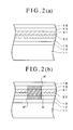
- dielectric materials contained in the first dielectric layer 15 and the second dielectric layer 13 are crystallized at a region irradiated with the laser beam L10 and, as shown in Figure 2(b), crystallized regions M' are formed in the first dielectric layer 15 and the second dielectric layer 13 so as to be adjacent to the record mark M.
- the power of the laser beam L10 is set to be equal to or higher than 1.5 mW at the surface of the light transmission layer 16.
- the reflection coefficient of the record mark M is different from those of other regions of the first recording layer 31 and the second recording layer 32, and data recorded in the optical recording medium 10 can be reproduced utilizing the difference in the reflection coefficients between the record mark M and other regions of the first recording layer 31 and the second recording layer 32.
- the difference in the reflection coefficient between the record mark M and other regions of the first recording layer 31 and the second recording layer 32 is not sufficiently large, a reproduced signal having a high C/N ratio cannot be obtained.
- the power of the laser beam L10 is modulated using a pulse train pattern including a recording power Pw and a ground power Pb.
- data are recorded in the optical recording medium 10 by projecting the laser beam L10 thereonto to form record marks M and crystallized regions M', and data recorded in the optical recording medium 10 are reproduced utilizing the difference in reflection coefficients between the regions where the record marks M and crystallized regions M' are formed and other regions.
- the pulse train pattern is therefore selected in accordance with the data recording linear velocity and the thermal conductivity of the first recording layer 31 and the second recording layer 32 so that the crystallized regions M' can be formed in the first dielectric layer 15 and the second dielectric layer 13 in a desired manner.
- the pulse train pattern for modulating the laser beam L10 is selected so that the amount of heat imparted to the first dielectric layer 15 and the second dielectric layer 13 becomes as large as possible.
- the pulse train pattern for modulating the laser beam L10 is selected so that the amount of heat imparted to the first dielectric layer 15 and the second dielectric layer 13 is not so large.
- Figure 3 is a diagram showing the waveform of a single pulse pattern for the case where 2T signal to 8T signal are recorded in the (1, 7) RLL modulation mode.
- the single pulse pattern shown in Figure 3 is one of a pulse train pattern preferably selected for modulating the power of a laser beam in the case where the recording linear velocity is high and the thermal conductivity of the first recording layer 31 and the second recording layer 32 is high.
- the single pulse has a width corresponding to the length of a record mark M to be formed and the laser beam is set to have a recording power Pw1 at the peak thereof and to have a ground power Pb1 at other times.
- the recording power Pw 1 is set to a high level at which the element contained in the first recording layer 31 as a primary component and the element contained in the second recording layer 32 as a primary component can be heated and mixed to form a record mark M and crystallized regions M' can be formed at regions of the first dielectric layer 15 and the second dielectric layer 13 adjacent to the record mark M when a laser beam having the recording power Pw1 is projected onto the optical recording medium 10.
- the ground power Pb1 is set to a low level at which the element contained in the first recording layer 31 as a primary component and the element contained in the second recording layer 32 as a primary component cannot be substantially mixed and no crystallized region M' can be formed in the first dielectric layer 15 and the second dielectric layer 13 when a laser beam having the ground power Pb1 is projected onto the optical recording medium 10.
- the ground power Pb1 is set higher than the reproducing power Pr.
- the temperature of the track can be raised as a whole by the laser beam having the ground power Pb1 and it is therefore possible to form a record mark M and crystallized regions M' without setting the level of the recording power Pw1 so high.
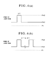
- Figure 4 is a diagram showing the waveform of a basic pulse train pattern wherein Figure 4 (a) shows a pulse train pattern for recording a 2T signal in the (1, 7) RLL modulation mode and Figure 4 (b) shows a pulse train pattern for recording 3T signal to 8T signal.
- the basic pulse train pattern shown in Figure 4 is a pulse train pattern preferably selected for modulating the power of the laser beam in the case where the recording linear velocity is low and the thermal conductivity of the first recording layer 31 and the second recording layer 32 is low.
- the pulse for forming a record mark M is divided into (n-1) pulses and the laser beam is set to have a recording power Pw2 at the peak of each of the divided pulses and to have a ground power Pb2 at other times.
- the power of the laser beam is modulated using the basic pulse train pattern, even if the recording linear velocity is low, the amount of heat imparted to the first recording layer 31 and the second recording layer 32 can be prevented from becoming too large and it is therefore possible to effectively prevent the width of the record mark from becoming large and crosstalk from increasing.
- the recording power Pw2 is set to a high level at which the element contained in the first recording layer 31 as a primary component and the element contained in the second recording layer 32 as a primary component can be heated and mixed to form a record mark M and crystallized regions M' can be formed at regions of the first dielectric layer 15 and the second dielectric layer 13 adjacent to the record mark M when a laser beam having the recording power Pw2 is projected onto the optical recording medium 10.
- the ground power Pb2 is set to a low level at which the element contained in the first recording layer 31 as a primary component and the element contained in the second recording layer 32 as a primary component cannot be substantially mixed and no crystallized region M' can be formed in the first dielectric layer 15 and the second dielectric layer 13 when a laser beam having the ground power Pb2 is projected onto the optical recording medium 10.
- the ground power Ph2 is set higher than the reproducing power Pr.
- the temperature of the track can be raised as a whole by the laser beam having the ground power Pb2 and it is therefore possible to form a record mark M and crystallized regions M' without setting the level of the recording power Pw2 so high.
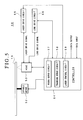
- Figure 5 is a block diagram showing a data recording apparatus for recording data in the optical recording medium 10.
- the data recording apparatus includes a spindle motor 52 for rotating the optical recording medium 10, a head 53 for projecting a laser beam L10 onto the optical recording medium 10 and receiving light reflected from the optical recording medium 10, a controller 54 for controlling the operations of the spindle motor 52 and the head 53, a laser drive circuit 55 for feeding a laser drive signal and a lens drive circuit 56 for feeding a lens drive signal to the head 53.
- the controller 54 includes a focus servo circuit 57, a tracking servo circuit 58 and a laser control circuit 59.
- a laser beam L10 is focused on the first recording layer 31 of the optical recording medium 10 being rotated and when the tracking servo circuit 58 is activated, the spot of the laser beam L10 automatically follows a track of the optical recording medium 10.
- the focus servo circuit 57 and the tracking servo circuit 58 have automatic gain control capability for automatically regulating focus gain and automatic gain control capability for automatically regulating tracking gain, respectively.
- the laser control circuit 59 generates the laser drive signal fed to the head 53 by the laser drive circuit 55.
- the optical recording medium 10 is prerecorded in the form of wobbles or pits with data for identifying the single pulse pattern or the basic pulse train pattern described above as data for setting the recording conditions and is also recorded with the recording linear velocity and other data for identifying recording conditions required to record data.
- the laser control circuit 59 reads the data for setting recording conditions recorded in the optical recording medium 10, selects the single pulse pattern or the basic pulse train pattern based on the thus read data for setting recording conditions, generates a laser drive signal, and causes the laser drive circuit 55 to output the laser drive signal to the head 53.
- a record mark M is formed by mixing the element contained in the first recording layer 31 as a primary component and the element contained in second recording layer 32 as a primary component and crystallized regions M' are formed at a regions of the first dielectric layer 15 and the second dielectric layer 13 adjacent to the record mark M, the difference in reflection coefficients between the region where the record mark M and the crystallized regions M' are formed and other regions can be made large as a whole and it is possible reproduce data recorded in the optical recording medium 10 utilizing the difference in reflection coefficients between the region where the record mark M and the crystallized regions M' are formed and other regions, thereby obtaining a reproduced signal having a high C/N ratio and reducing jitter of the reproduced signal.
- An optical recording medium sample # 1 having the same structure as that shown in Figure 1 was fabricated in the following manner.
- a polycarbonate substrate having a thickness of 1.1 mm and a diameter of 120 mm was first set on a sputtering apparatus. Then, a reflective layer containing Ag as a primary component and having a thickness of 100 nm, a second dielectric layer containing a mixture of ZnS and SiO 2 and having a thickness of 28 nm, a second recording layer containing Cu as a primary component, added with 21 atomic % of Mg and having a thickness of 5 nm, a first recording layer containing Si as a primary component and having a thickness of 5 nm and a first dielectric layer containing the mixture of ZnS and SiO 2 and having a thickness of 22 nm were sequentially formed on the polycarbonate substrate using the sputtering process.
- the mole ratio of ZnS to SiO 2 in the mixture of ZnS and SiO 2 contained in the first dielectric layer and the second dielectric layer was 80:20.
- the first dielectric layer was coated using the spin coating method with a resin solution prepared by dissolving acrylic ultraviolet ray curable resin in a solvent to form a coating layer and the coating layer was irradiated with ultraviolet rays, thereby curing the acrylic ultraviolet ray curable resin to form a light transmission layer having a thickness of 100 ⁇ m.
- An optical recording medium sample # 2 was fabricated in the manner of the optical recording medium sample # 1, except that a second recording layer was formed by adding 17 atomic % of Al instead of Mg.
- Each of the optical recording medium samples # 1 and # 2 was set in a DDU1000 optical recording medium evaluation apparatus manufactured by Pulstec Industrial Co., Ltd., a blue laser beam having a wavelength of 405 nm was employed as the laser beam for recording data and the laser beam was condensed onto each of the optical recording media via the light transmission layer using an objective lens whose numerical aperture was 0.85, and data were optically recorded therein under the following recording signal conditions.
- the power of the laser beam was modulated using the basic pulse train pattern shown in Figure 4 so that the width of each pulse was set to be 0.5 T, the ground power Pb2 was set to be 0.1 mW and the recording power Pw2 was set to be 5.0 mW.
- the data transfer rate was about 35 Mbps assuming that the format efficiency was 80 %.
- the first recording layer and the second recording layer in each of the optical recording medium samples # 1 and # 2 were observed using an Auger analysis apparatus and the first dielectric layer and the second dielectric layer thereof were observed using a transmission electron microscope.
- An optical recording medium sample # 3 was fabricated in the manner of the optical recording medium sample # 1, except that a second recording layer containing Al as the primary component and added with 17 atomic % of Mg was formed.
- An optical recording medium sample # 4 was fabricated in the manner of the optical recording medium sample # 1, except that a second recording layer containing Cu as the primary component and added with 23 atomic % of Al and 12.8 atomic % of Au was formed.
- the ground power Pb1 of the single pulse pattern was set to 0.1 mW and the recording power Pw 1 thereof was set to 3.8 mW.
- the width of each pulse of the basic pulse train pattern was set to 0.3 T, the ground power Pb2 thereof was set to 0.1 mW and the recording power Pw2 thereof was set to 5.0 mW.
- the first recording layer, the second recording layer, the first dielectric layer and the second dielectric layer of the optical recording medium sample # 4 were further observed in each of the case where data were recorded using the laser beam whose power was modulated in accordance with the single pulse pattern and the case where data were recorded using the laser beam whose power was modulated in accordance with the basic pulse train pattern.
- An optical recording medium sample # 5 was fabricated in the following manner.
- a polycarbonate substrate having a thickness of 1.1 mm and a diameter of 120 mm was first set on a sputtering apparatus. Then, a reflective layer containing Ag as a primary component and having a thickness of 100 nm, a second dielectric layer containing a mixture of ZnS and SiO 2 and having a thickness of 30 nm, a recording layer containing Sn as a primary component and having a thickness of 3 nm, and a first dielectric layer containing the mixture of ZnS and SiO 2 and having a thickness of 30 nm were sequentially formed on the polycarbonate substrate using the sputtering process.
- the mole ratio of ZnS to SiO 2 in the mixture of ZnS and SiO 2 contained in the first dielectric layer and the second dielectric layer was 80:20.
- the first dielectric layer was coated using the spin coating method with a resin solution prepared by dissolving acrylic ultraviolet ray curable resin in a solvent to form a coating layer and the coating layer was irradiated with ultraviolet rays, thereby curing the acrylic ultraviolet ray curable resin to form a light transmission layer having a thickness of 100 ⁇ m.
- the width of each pulse of the basic pulse train pattern was set to 0.6 T, the ground power Pb2 thereof was set to 0.1 mW and the recording power Pw2 thereof was set to 9.0 mW.
- An optical recording medium sample # 6 was fabricated in the following manner.
- a polycarbonate substrate having a thickness of 1.1 mm and a diameter of 120 mm was first set on a sputtering apparatus. Then, a second dielectric layer containing a mixture of ZnS and SiO 2 and having a thickness of 100 nm, a recording layer containing Sn as a primary component and having a thickness of 3.5 nm, and a first dielectric layer containing the mixture of ZnS and SiO 2 and having a thickness of 80 nm were sequentially formed on the polycarbonate substrate using the sputtering process.
- the mole ratio of ZnS to SiO 2 in the mixture of ZnS and SiO 2 contained in the first dielectric layer and the second dielectric layer was 80:20.
- the first dielectric layer was coated using the spin coating method with a resin solution prepared by dissolving acrylic ultraviolet ray curable resin in a solvent to form a coating layer and the coating layer was irradiated with ultraviolet rays, thereby curing the acrylic ultraviolet ray curable resin to form a light transmission layer having a thickness of 100 ⁇ m.
- the width of each pulse of the basic pulse train pattern was set to 0.6 T, the ground power Pb2 thereof was set to 0.1 mW and the recording power Pw2 thereof was set to 8.0 mW.
- An optical recording medium sample # 7 was fabricated in the following manner.
- a polycarbonate substrate having a thickness of 1.1 mm and a diameter of 120 mm was first set on a sputtering apparatus. Then, a dielectric layer containing a mixture of ZnS and SiO 2 and having a thickness of 60 nm and a recording layer containing Sn as a primary component and having a thickness of 6 nm were sequentially formed on the polycarbonate substrate using the sputtering process.
- the mole ratio of ZnS to SiO 2 in the mixture of ZnS and SiOg contained in the dielectric layer was 80:20.
- the recording layer was coated using the spin coating method with a resin solution prepared by dissolving acrylic ultraviolet ray curable resin in a solvent to form a coating layer and the coating layer was irradiated with ultraviolet rays, thereby curing the acrylic ultraviolet ray curable resin to form a light transmission layer having a thickness of 100 ⁇ m.
- the width of each pulse of the basic pulse train pattern was set to 0.6 T, the ground power Pb2 thereof was set to 0.1 mW and the recording power Pw2 thereof was set to 7.0 mW.
- ZnS crystal was observed at regions of the dielectric layer adjacent to a region of the recording layer irradiated with the laser beam having the recording power Pw2.
- An optical recording medium sample # 8 was fabricated in the following manner.
- a polycarbonate substrate having a thickness of 1.1 mm and a diameter of 120 mm was first set on a sputtering apparatus. Then, a second dielectric layer containing a mixture of ZnS and SiO 2 and having a thickness of 20 nm, a recording layer containing Ti as a primary component and having a thickness of 10 nm, and a first dielectric layer containing the mixture of ZnS and SiO 2 and having a thickness of 20 nm were sequentially formed on the polycarbonate substrate using the sputtering process.
- the mole ratio of ZnS to SiO 2 in the mixture of ZnS and SiO 2 contained in the first dielectric layer and the second dielectric layer was 80:20.
- the first dielectric layer was coated using the spin coating method with a resin solution prepared by dissolving acrylic ultraviolet ray curable resin in a solvent to form a coating layer and the coating layer was irradiated with ultraviolet rays, thereby curing the acrylic ultraviolet ray curable resin to form a light transmission layer having a thickness of 100 ⁇ m.
- the width of each pulse of the basic pulse train pattern was set to 0.6 T, the ground power Pb2 thereof was set to 0.1 mW and the recording power Pw2 thereof was set to 10.0 mW.
- the optical recording medium 10 is provided with the first recording layer 31 and the second recording layer 32, it is not absolutely necessary for the optical recording medium to be provided with two recording layers 31, 32 and the present invention can be widely applied also to an optical recording medium provided with a single recording layer.
- first recording layer 31 and the second recording layer 32 are formed in contact with each other, it is not absolutely necessary to form the first recording layer 31 and the second recording layer 32 in contact with each other but it is sufficient for the second recording layer 32 to be so located in the vicinity of the first recording layer 31 as to enable formation of a mixed region including the primary component element of the first recording layer 31 and the primary component element of the second recording layer 32 when the region is irradiated with a laser beam. Further, one or more other layers such as a dielectric layer may be interposed between the first recording layer 31 and the second recording layer 32.
- the optical recording medium 10 in the above described embodiment includes the first recording layer 31 and the second recording layer 32
- the optical recording medium may include one or more recording layers containing as a primary component, the element contained in the first recording layer 31 as a primary component or one or more recording layers containing as a primary component, the element contained in the second recording layer 32 as a primary element, in addition to the first recording layer 31 and the second recording layer 32.
- the optical recording medium 10 in the above described embodiment includes the first dielectric layer 15 and the second dielectric layer 13 and the first recording layer 31 and the second recording layer 32 are disposed between the first dielectric layer 15 and the second dielectric layer 13.
- the optical recording medium 10 may include a single dielectric layer and in such a case, the dielectric layer may be disposed on either the side of the substrate 11 or the side of the light transmission layer 16 with respect to the first recording layer 31 and the second recording layer 32.
- first recording layer 31 and the second recording layer 32 are formed so as to have the same thickness in the above described embodiment and working examples, it is not absolutely necessary to form the first recording layer 31 and the second recording layer 32 so as to have the same thickness.
- the first recording layer 31 is disposed on the side of the light transmission layer 16 and the second recording layer 32 is disposed on the side of the substrate 11 in the above described embodiment and working examples, it is possible to dispose the first recording layer 31 on the side of the substrate 11 and the second recording layer 32 on the side of the light transmission layer 16.
- the crystallized regions M' are formed throughout the regions of the first dielectric layer 15 and the second dielectric layer 13 adjacent to the record mark M, it is not absolutely necessary for the crystallized regions M' to be formed throughout the regions of the first dielectric layer 15 and the second dielectric layer 13 adjacent to the record mark M and it is sufficient for the crystallized regions M' to be formed in at least a part of regions of the first dielectric layer 15 or the second dielectric layer 13 adjacent to the record mark M.
- the present invention is not limited to the next-generation optical recording medium and can be widely applied to write-once type optical recording media.
- an optical recording medium capable of reproducing a signal having excellent signal characteristics.
Landscapes
- Chemical & Material Sciences (AREA)
- Inorganic Chemistry (AREA)
- Optical Record Carriers And Manufacture Thereof (AREA)
- Thermal Transfer Or Thermal Recording In General (AREA)
Applications Claiming Priority (2)
| Application Number | Priority Date | Filing Date | Title |
|---|---|---|---|
| JP2002191613 | 2002-07-01 | ||
| JP2002191613 | 2002-07-01 |
Publications (2)
| Publication Number | Publication Date |
|---|---|
| EP1378894A2 true EP1378894A2 (fr) | 2004-01-07 |
| EP1378894A3 EP1378894A3 (fr) | 2004-11-24 |
Family
ID=29720221
Family Applications (1)
| Application Number | Title | Priority Date | Filing Date |
|---|---|---|---|
| EP03014433A Withdrawn EP1378894A3 (fr) | 2002-07-01 | 2003-06-30 | Support d' enregistrement optique et procédé pour y enregistrer des données |
Country Status (2)
| Country | Link |
|---|---|
| US (2) | US20040038080A1 (fr) |
| EP (1) | EP1378894A3 (fr) |
Families Citing this family (26)
| Publication number | Priority date | Publication date | Assignee | Title |
|---|---|---|---|---|
| TWI254301B (en) * | 2002-04-05 | 2006-05-01 | Tdk Corp | Optical recording medium and method for optically recording information in the same |
| TWI254934B (en) * | 2002-04-26 | 2006-05-11 | Tdk Corp | Optical recording medium and method for optically recording data in the same |
| TWI277076B (en) * | 2002-06-03 | 2007-03-21 | Tdk Corp | Regeneration method for optical recording, and optical recording medium |
| US20040038080A1 (en) * | 2002-07-01 | 2004-02-26 | Tdk Corporation | Optical recording medium and method for recording data in the same |
| JP4092147B2 (ja) * | 2002-07-04 | 2008-05-28 | Tdk株式会社 | 光記録媒体及び光記録方法 |
| JP4282285B2 (ja) * | 2002-08-12 | 2009-06-17 | Tdk株式会社 | 光記録媒体及び光記録方法 |
| US20040076907A1 (en) * | 2002-10-22 | 2004-04-22 | Tdk Corporation | Optical recording medium and method for manufacturing the same |
| US7781146B2 (en) * | 2002-11-22 | 2010-08-24 | Tdk Corporation | Optical recording medium |
| US7932015B2 (en) | 2003-01-08 | 2011-04-26 | Tdk Corporation | Optical recording medium |
| JP2004355743A (ja) * | 2003-05-30 | 2004-12-16 | Tdk Corp | 光情報記録媒体 |
| JP2005044395A (ja) * | 2003-07-23 | 2005-02-17 | Tdk Corp | 光情報記録媒体 |
| JP2005071408A (ja) * | 2003-08-25 | 2005-03-17 | Tdk Corp | 光情報記録媒体 |
| JP2005071402A (ja) * | 2003-08-25 | 2005-03-17 | Tdk Corp | 光情報記録媒体 |
| JP2005302275A (ja) * | 2004-03-18 | 2005-10-27 | Sharp Corp | 光情報記録媒体、記録再生方法、ならびに記録再生装置 |
| JP2006240289A (ja) * | 2005-02-07 | 2006-09-14 | Kobe Steel Ltd | 光情報記録媒体用記録膜および光情報記録媒体ならびにスパッタリングターゲット |
| US20080057255A2 (en) * | 2005-10-20 | 2008-03-06 | Lanyo Technology Co., Ltd. | Contrast Inversion for Optical Recording |
| US20080056088A2 (en) * | 2005-10-20 | 2008-03-06 | Lanyo Technology Co., Ltd. | Multiple Recording Structures for Optical Recording |
| US20070092681A1 (en) * | 2005-10-20 | 2007-04-26 | Shuy Geoffrey W | Generating optical contrast using thin layers |
| US20080056089A2 (en) * | 2005-10-20 | 2008-03-06 | Lanyo Technology Co., Ltd. | Generating Optical Contrast Using Thin Layers |
| JP2007157314A (ja) * | 2005-11-10 | 2007-06-21 | Canon Inc | 追記型光ディスク及び光記録方法 |
| EP2094268A2 (fr) * | 2006-05-26 | 2009-09-02 | Bayer HealthCare, LLC | Associations de médicaments comportant des urées de diaryle substituées pour le traitement du cancer |
| JP2009032307A (ja) * | 2007-07-25 | 2009-02-12 | Tdk Corp | 光情報媒体 |
| US8119218B2 (en) * | 2008-11-06 | 2012-02-21 | Lg Electronics Inc. | Optical recording medium |
| US8119219B2 (en) * | 2008-11-06 | 2012-02-21 | Lg Electronics Inc. | Optical recording medium |
| JP2011204307A (ja) * | 2010-03-25 | 2011-10-13 | Tdk Corp | 光記録媒体、光記録方法 |
| JP2011238324A (ja) * | 2010-05-13 | 2011-11-24 | Tdk Corp | 光記録媒体、光記録方法 |
Family Cites Families (84)
| Publication number | Priority date | Publication date | Assignee | Title |
|---|---|---|---|---|
| US3959799A (en) * | 1974-09-09 | 1976-05-25 | International Business Machines Corporation | Information storage by laser beam initiated reactions |
| US4357616A (en) * | 1979-03-26 | 1982-11-02 | Hitachi, Ltd. | Recording medium |
| JPS5841311A (ja) * | 1981-09-07 | 1983-03-10 | Nippon Soken Inc | 静電容量式回転検出装置 |
| EP0089168B1 (fr) * | 1982-03-15 | 1986-07-23 | Kabushiki Kaisha Toshiba | Support d'enregistrement d'information par voie optique |
| US4477819A (en) * | 1982-06-14 | 1984-10-16 | International Business Machines Corporation | Optical recording medium |
| JPS6028045A (ja) * | 1983-07-25 | 1985-02-13 | Sony Corp | 情報記録媒体 |
| JPS60187933A (ja) * | 1984-03-07 | 1985-09-25 | Toshiba Corp | 光学的記録再生装置 |
| US4670345A (en) * | 1985-02-22 | 1987-06-02 | Asahi Kasei Kogyo Kabushiki Kaisha | Information recording medium |
| JPH0695388B2 (ja) * | 1985-06-14 | 1994-11-24 | 株式会社東芝 | 情報記録媒体 |
| WO1988003310A1 (fr) * | 1986-10-29 | 1988-05-05 | Dai Nippon Insatsu Kabushiki Kaisha | Support d'enregistrement optique du type draw |
| US5194363A (en) * | 1990-04-27 | 1993-03-16 | Matsushita Electric Industrial Co., Ltd. | Optical recording medium and production process for the medium |
| US5325351A (en) * | 1990-10-22 | 1994-06-28 | Tdk Corporation | Optical recording medium having a reflective layer made of Cu-Ag or Cu-Au alloy |
| JP2813844B2 (ja) * | 1990-11-22 | 1998-10-22 | ティーディーケイ株式会社 | 光記録媒体 |
| JP3266627B2 (ja) * | 1991-10-11 | 2002-03-18 | 株式会社日立製作所 | 情報再生装置 |
| JPH0677510A (ja) * | 1992-08-24 | 1994-03-18 | Canon Inc | 光起電力素子 |
| JPH06139621A (ja) * | 1992-10-29 | 1994-05-20 | Matsushita Electric Ind Co Ltd | 光記録媒体 |
| US5709978A (en) * | 1993-06-18 | 1998-01-20 | Hitachi, Ltd. | Supperresolution readout thin film and information recording medium |
| US5458941A (en) * | 1994-06-09 | 1995-10-17 | Minnesota Mining And Manufacturing Company | Optical recording medium exhibiting eutectic phase equilbria |
| JPH08235641A (ja) * | 1995-02-27 | 1996-09-13 | Sony Corp | 光学記録媒体とその製法 |
| KR100411658B1 (ko) * | 1995-03-27 | 2004-04-03 | 히다치 마쿠세루가부시키가이샤 | 정보기록매체및정보메모리장치 |
| DE69738285T2 (de) * | 1996-09-06 | 2008-02-28 | Ricoh Co., Ltd. | Optisches Speichermedium |
| US5914214A (en) * | 1996-12-06 | 1999-06-22 | Matsushita Electric Industrial Co., Ltd. | Method for manufacturing an optical information recording medium |
| EP0971345B1 (fr) * | 1996-12-19 | 2006-05-03 | Matsushita Electric Industrial Co., Ltd. | Disque optique et procede d'enregistrement sur disque optique |
| US6033752A (en) * | 1997-05-22 | 2000-03-07 | Kao Corporation | Optical recording medium and method for recording optical information |
| US6231945B1 (en) * | 1997-09-09 | 2001-05-15 | Hitachi, Ltd. | Information recording medium |
| JP3584472B2 (ja) * | 1997-10-17 | 2004-11-04 | 株式会社豊田中央研究所 | 光記憶媒体 |
| JPH11240252A (ja) * | 1997-12-22 | 1999-09-07 | Tdk Corp | 光記録媒体 |
| DE69928190T2 (de) * | 1998-02-24 | 2006-07-27 | Sony Corp. | Optisches aufzeichnungsmedium |
| US6210860B1 (en) * | 1998-04-09 | 2001-04-03 | Kabushiki Kaisha Toyota Chuo Kenkyusho | Recording medium |
| US6544616B2 (en) * | 2000-07-21 | 2003-04-08 | Target Technology Company, Llc | Metal alloys for the reflective or the semi-reflective layer of an optical storage medium |
| US6254966B1 (en) * | 1998-08-04 | 2001-07-03 | Victor Company Of Japan, Ltd. | Information recording mediums, supporter used in the mediums, manufacture methods of the supporter, manufacturing apparatus of the supporter and stampers for producing the mediums |
| US6355326B1 (en) * | 1998-09-30 | 2002-03-12 | Skc Limited | Phase change optical disk |
| US6636477B1 (en) * | 1998-10-07 | 2003-10-21 | Hitachi, Ltd. | Information recording medium and information recording device |
| US6449239B1 (en) * | 1998-11-25 | 2002-09-10 | Matsushita Electric Industrial Co., Ltd. | Optical information recording medium with thermal diffusion layer |
| US6660451B1 (en) * | 1999-06-18 | 2003-12-09 | Matsushita Electric Industrial Co., Ltd. | Optical information recording medium |
| WO2001004888A1 (fr) * | 1999-07-12 | 2001-01-18 | Matsushita Electric Industrial Co., Ltd. | Support d'enregistrement d'information optique et procede d'initialisation correspondant |
| JP4433654B2 (ja) * | 1999-07-22 | 2010-03-17 | ソニー株式会社 | 光記録媒体 |
| WO2001016947A1 (fr) * | 1999-08-31 | 2001-03-08 | Kabushiki Kaisha Toshiba | Disque optique, procede et appareil de lecture de donnees dudit disque |
| TW527585B (en) * | 2000-02-21 | 2003-04-11 | Ind Tech Res Inst | Compact disk device, access method of compact disk, and the compact disk |
| JP2001344824A (ja) * | 2000-03-30 | 2001-12-14 | Tdk Corp | 光記録媒体の製造方法および光記録媒体 |
| JP2001307393A (ja) * | 2000-04-25 | 2001-11-02 | Canon Inc | 光磁気再生装置 |
| JP2002157737A (ja) * | 2000-05-12 | 2002-05-31 | Tdk Corp | 光記録方法および光記録媒体 |
| TW575873B (en) * | 2000-07-13 | 2004-02-11 | Matsushita Electric Industrial Co Ltd | Information recording medium, method for producing the same, and recording/reproducing method using the same |
| TWI233098B (en) * | 2000-08-31 | 2005-05-21 | Matsushita Electric Industrial Co Ltd | Data recoding medium, the manufacturing method thereof, and the record reproducing method thereof |
| EP1193696B1 (fr) * | 2000-09-28 | 2007-01-03 | Ricoh Company, Ltd. | Support d'enregistrement optique, procédé de fabrication de ce support d'enregistrement optique et méthode et appareil pour enregistrer sur et reproduire à partir du support d'enregistrement optique |
| US6700862B2 (en) * | 2000-10-03 | 2004-03-02 | Matsushita Electric Industrial Co., Ltd. | Optical disc and manufacturing method for the same |
| JP2002117576A (ja) * | 2000-10-03 | 2002-04-19 | Tdk Corp | 光記録媒体および光学的情報記録方法 |
| TWI246681B (en) * | 2000-12-15 | 2006-01-01 | Koninkl Philips Electronics Nv | Optical information medium and its use |
| US7088666B2 (en) * | 2001-07-05 | 2006-08-08 | Samsung Electronics Co., Ltd. | High density optical disk having capacity of 25GB |
| JP2003203338A (ja) * | 2001-12-28 | 2003-07-18 | Tdk Corp | 光記録媒体の記録方法及び光記録媒体 |
| US6899938B2 (en) * | 2002-02-22 | 2005-05-31 | Energy Conversion Devices, Inc. | Phase change data storage device for multi-level recording |
| EP1347448B1 (fr) * | 2002-03-22 | 2005-11-23 | Ricoh Company, Ltd. | Support d'enregistrement optique et procédé d'enregistrement utilisant ledit support |
| JP2003281780A (ja) * | 2002-03-26 | 2003-10-03 | Toshiba Corp | 光記録媒体 |
| TWI254301B (en) * | 2002-04-05 | 2006-05-01 | Tdk Corp | Optical recording medium and method for optically recording information in the same |
| TWI254934B (en) * | 2002-04-26 | 2006-05-11 | Tdk Corp | Optical recording medium and method for optically recording data in the same |
| US6996055B2 (en) * | 2002-04-30 | 2006-02-07 | Tdk Corporation | Optical recording medium and method for optically recording data in the same |
| JP2003331461A (ja) * | 2002-05-15 | 2003-11-21 | Pioneer Electronic Corp | 追記型光記録媒体 |
| US7231649B2 (en) * | 2002-05-31 | 2007-06-12 | Tdk Corporation | Optical recording medium and method for optically recording data in the same |
| JP2004013947A (ja) * | 2002-06-04 | 2004-01-15 | Victor Co Of Japan Ltd | 情報記録担体、再生装置、記録装置、記録再生装置、再生方法、記録方法及び記録再生方法 |
| US20040038080A1 (en) * | 2002-07-01 | 2004-02-26 | Tdk Corporation | Optical recording medium and method for recording data in the same |
| JP4059714B2 (ja) * | 2002-07-04 | 2008-03-12 | Tdk株式会社 | 光記録媒体 |
| JP4092147B2 (ja) * | 2002-07-04 | 2008-05-28 | Tdk株式会社 | 光記録媒体及び光記録方法 |
| JP4282285B2 (ja) * | 2002-08-12 | 2009-06-17 | Tdk株式会社 | 光記録媒体及び光記録方法 |
| US20040076907A1 (en) * | 2002-10-22 | 2004-04-22 | Tdk Corporation | Optical recording medium and method for manufacturing the same |
| US7781146B2 (en) * | 2002-11-22 | 2010-08-24 | Tdk Corporation | Optical recording medium |
| US7932015B2 (en) * | 2003-01-08 | 2011-04-26 | Tdk Corporation | Optical recording medium |
| JP4084674B2 (ja) * | 2003-01-28 | 2008-04-30 | Tdk株式会社 | 光記録媒体 |
| JP2004265561A (ja) * | 2003-03-04 | 2004-09-24 | Tdk Corp | 光記録媒体 |
| JP4053916B2 (ja) * | 2003-03-24 | 2008-02-27 | Tdk株式会社 | 光記録媒体及び光記録媒体用スパッタリングターゲット |
| JP4090377B2 (ja) * | 2003-03-28 | 2008-05-28 | Tdk株式会社 | 光記録媒体 |
| US20040202097A1 (en) * | 2003-04-08 | 2004-10-14 | Tdk Corporation | Optical recording disk |
| US6965245B2 (en) * | 2003-05-01 | 2005-11-15 | K&S Interconnect, Inc. | Prefabricated and attached interconnect structure |
| JP2004355743A (ja) * | 2003-05-30 | 2004-12-16 | Tdk Corp | 光情報記録媒体 |
| JP3868406B2 (ja) * | 2003-07-07 | 2007-01-17 | Tdk株式会社 | 光記録媒体へのデータの記録方法および光記録媒体へのデータの記録装置 |
| JP2005044395A (ja) * | 2003-07-23 | 2005-02-17 | Tdk Corp | 光情報記録媒体 |
| JP2005044397A (ja) * | 2003-07-23 | 2005-02-17 | Tdk Corp | 光情報記録媒体 |
| JP2005044396A (ja) * | 2003-07-23 | 2005-02-17 | Tdk Corp | 光情報記録媒体 |
| JP2005071406A (ja) * | 2003-08-25 | 2005-03-17 | Tdk Corp | 光情報記録媒体 |
| JP2005071403A (ja) * | 2003-08-25 | 2005-03-17 | Tdk Corp | 光情報記録媒体 |
| JP2005071402A (ja) * | 2003-08-25 | 2005-03-17 | Tdk Corp | 光情報記録媒体 |
| JP2005071405A (ja) * | 2003-08-25 | 2005-03-17 | Tdk Corp | 光情報記録媒体 |
| JP2005071408A (ja) * | 2003-08-25 | 2005-03-17 | Tdk Corp | 光情報記録媒体 |
| JP2005071407A (ja) * | 2003-08-25 | 2005-03-17 | Tdk Corp | 光情報記録媒体 |
| ITVR20030049U1 (it) * | 2003-10-01 | 2005-04-02 | Montresor & C Srl | Dispositivo a dima per il controllo della movimentazione di frese diam antate o simili, applicabile su macchine lucidacoste di lastre in mate riale lapideo. |
-
2003
- 2003-06-27 US US10/608,814 patent/US20040038080A1/en not_active Abandoned
- 2003-06-30 EP EP03014433A patent/EP1378894A3/fr not_active Withdrawn
-
2005
- 2005-11-07 US US11/268,109 patent/US20060078825A1/en not_active Abandoned
Also Published As
| Publication number | Publication date |
|---|---|
| US20060078825A1 (en) | 2006-04-13 |
| US20040038080A1 (en) | 2004-02-26 |
| EP1378894A3 (fr) | 2004-11-24 |
Similar Documents
| Publication | Publication Date | Title |
|---|---|---|
| EP1378894A2 (fr) | Support d' enregistrement optique et procédé pour y enregistrer des données | |
| US7018695B2 (en) | Optical recording medium | |
| US6929840B2 (en) | Optical recording medium, method for manufacturing the same and target used for sputtering process | |
| US20040157158A1 (en) | Optical recording medium | |
| US7018694B2 (en) | Optical recording medium, method for manufacturing the same and target used for sputtering process | |
| US7002887B2 (en) | Method of recording data in optical recording medium and an apparatus for recording data in optical recording medium | |
| EP1394786B1 (fr) | Support d'enregistrement optique et procédé d'enregistrement des données optiques sur lemême | |
| EP1533796A1 (fr) | Procede de decision de motif de modulation de puissance de faisceau laser, dispositif permettant d'enregistrer des donnees sur un support d'enregistrement optique, et support d'enregistrement optique | |
| US7351516B2 (en) | Optical information recording medium | |
| US20040208105A1 (en) | Optical recording medium | |
| US20040191689A1 (en) | Optical recording medium and data recording medium for recording data in the same | |
| JP2003054135A (ja) | 光記録媒体および光記録方法 | |
| EP1276105B1 (fr) | Support d'enregistrement optique et procédé l'utilisant | |
| JP3790673B2 (ja) | 光記録方法、光記録装置および光記録媒体 | |
| US20040213124A1 (en) | Optical recording medium and data recording apparatus for recording data in the same | |
| US7136343B2 (en) | Optical recording/reproducing method and optical recording medium | |
| JPH11115313A (ja) | 光記録媒体及びこれの記録再生方法 | |
| US7525891B2 (en) | Method for recording data in optical recording medium, an apparatus for recording data in optical recording medium and optical recording medium | |
| US7554892B2 (en) | Method for recording data in optical recording medium, an apparatus for recording data in optical recording medium and optical recording medium | |
| US20040027983A1 (en) | Optical recording/reproducing method and optical recording medium | |
| US7443775B2 (en) | Method for recording data in optical recording medium, and apparatus for recording data in optical recording medium and optical recording medium | |
| JP2004047053A (ja) | 光記録媒体へのデータの記録方法、光記録媒体へのデータの記録装置および光記録媒体 | |
| JP2004158167A (ja) | 光記録媒体および光記録媒体へのデータ記録方法 | |
| US20050118530A1 (en) | Optical recording medium | |
| JP2003091873A (ja) | 光学的情報記録媒体およびそれを用いた記録方法 |
Legal Events
| Date | Code | Title | Description |
|---|---|---|---|
| PUAI | Public reference made under article 153(3) epc to a published international application that has entered the european phase |
Free format text: ORIGINAL CODE: 0009012 |
|
| AK | Designated contracting states |
Kind code of ref document: A2 Designated state(s): AT BE BG CH CY CZ DE DK EE ES FI FR GB GR HU IE IT LI LU MC NL PT RO SE SI SK TR |
|
| AX | Request for extension of the european patent |
Extension state: AL LT LV MK |
|
| RIN1 | Information on inventor provided before grant (corrected) |
Inventor name: AOSHIMA, MASAKI Inventor name: MISHIMA, KOJI Inventor name: INOUE, HIROYASU |
|
| PUAL | Search report despatched |
Free format text: ORIGINAL CODE: 0009013 |
|
| AK | Designated contracting states |
Kind code of ref document: A3 Designated state(s): AT BE BG CH CY CZ DE DK EE ES FI FR GB GR HU IE IT LI LU MC NL PT RO SE SI SK TR |
|
| AX | Request for extension of the european patent |
Extension state: AL LT LV MK |
|
| 17P | Request for examination filed |
Effective date: 20050128 |
|
| 17Q | First examination report despatched |
Effective date: 20050523 |
|
| AKX | Designation fees paid |
Designated state(s): DE GB |
|
| STAA | Information on the status of an ep patent application or granted ep patent |
Free format text: STATUS: THE APPLICATION IS DEEMED TO BE WITHDRAWN |
|
| 18D | Application deemed to be withdrawn |
Effective date: 20051004 |