EP1380231A1 - Dispositif de fixation d'un rail de guidage à une paroi - Google Patents
Dispositif de fixation d'un rail de guidage à une paroi Download PDFInfo
- Publication number
- EP1380231A1 EP1380231A1 EP03012455A EP03012455A EP1380231A1 EP 1380231 A1 EP1380231 A1 EP 1380231A1 EP 03012455 A EP03012455 A EP 03012455A EP 03012455 A EP03012455 A EP 03012455A EP 1380231 A1 EP1380231 A1 EP 1380231A1
- Authority
- EP
- European Patent Office
- Prior art keywords
- web
- fitting
- wall
- guide rail
- holding device
- Prior art date
- Legal status (The legal status is an assumption and is not a legal conclusion. Google has not performed a legal analysis and makes no representation as to the accuracy of the status listed.)
- Withdrawn
Links
- 239000002184 metal Substances 0.000 abstract description 2
- 210000002105 tongue Anatomy 0.000 abstract 3
- 230000015572 biosynthetic process Effects 0.000 description 2
- 230000037431 insertion Effects 0.000 description 1
- 238000003780 insertion Methods 0.000 description 1
- 238000009434 installation Methods 0.000 description 1
- 239000000463 material Substances 0.000 description 1
- 230000003287 optical effect Effects 0.000 description 1
- 238000005096 rolling process Methods 0.000 description 1
Images




Classifications
-
- A—HUMAN NECESSITIES
- A47—FURNITURE; DOMESTIC ARTICLES OR APPLIANCES; COFFEE MILLS; SPICE MILLS; SUCTION CLEANERS IN GENERAL
- A47B—TABLES; DESKS; OFFICE FURNITURE; CABINETS; DRAWERS; GENERAL DETAILS OF FURNITURE
- A47B88/00—Drawers for tables, cabinets or like furniture; Guides for drawers
- A47B88/40—Sliding drawers; Slides or guides therefor
- A47B88/423—Fastening devices for slides or guides
- A47B88/43—Fastening devices for slides or guides at cabinet side
Definitions
- the present invention relates to a device for fastening a guide rail on a wall, in particular a rear wall of a pull-out guide, according to the preamble of claim 1.
- DE 38 32 701 discloses a fastening arrangement for a guide rail a pull-out guide known in which a guide rail at the rear end has a folded tab that has locking teeth on the side edges is.
- This tab can be inserted into a bracket fitting on the rear wall a piece of furniture can be fixed.
- the bracket fitting has two web sections on, between which a receiving opening for inserting the tab is provided.
- locking teeth are in turn provided are resiliently connected to the locking teeth of the tab.
- This task is accomplished with a device for fastening a guide rail solved on a wall with the features of claim 1.
- the fitting has a spacing from the guide section Sidewall and the guide rail is stepless between a first end position, in which the guide rail laterally on the guide section of the fitting abuts, and a second end position in which the guide rail on the Sidewall abuts, slidable.
- the stepless adjustability is a finer one Adjustment of the guide rail on the fitting possible.
- the web-shaped holding device is steplessly movable between the two end positions, including larger ones Forces absorbed by the interconnected walls of the fitting can be. An unintentional pulling out is also caused by the side wall the guide rail avoided.
- the web-shaped holding device held clamped in the elastic guide portion.
- the clamping can take place both in the vertical and in the horizontal direction, preferably edge-shaped clamping takes place in which good guidance is ensured becomes.
- the guide rail only by a combined swivel and Moving movement can be removed from the fitting. With a side Adjustment is prevented, however, that the guide rail inadvertently from the Fitting is removed, since then the side wall serves as a stop.
- the web-shaped holding device preferably has two webs, each in a receptacle formed on the guide section can be inserted.
- the formation of two webs is the surface used for guidance on the Fitting enlarged, because there is a space between the webs, in the guide elements of the fitting can intervene. This improves the guidance of the web-shaped Holding device and also prevents rotation of the holding device within the fitting.
- the web-shaped holding device can be in the area of the guide section and adjacent to the guide section substantially positively guided on the upper and lower side wall of the fitting his.
- at least one web can be provided within the guide section be applied to the web-shaped holding device for guidance and can also ensure a certain clamping.
- the holding device With such webs you can Guide the holding device along several edges so that a particularly precise fit Movement within the recording is possible.
- Pins are preferably formed on the rear wall of the fitting Openings can be hung on a wall. This allows the fitting to be opened easy to mount on a piece of furniture. Show for secure attachment the pins on a flange portion, with a wall between the Flange section and the rear wall of the fitting is insertable.
- the guide rail 3 is in a side area on a wall, not shown, or on the Furniture front or a front frame 5 of a piece of furniture set and thus stationary.
- the guide rail 3 is connected to the fitting 2 via a web-shaped holding device 6, which is on the face of the Guide rail 3 is formed.
- the guide rail 3 is C-shaped and comprises a middle section 30, on which an upper leg 31 with a Front edge 32 and a lower leg 33 are formed.
- On the guide rail Rolling elements can be provided in a known manner.
- the web-shaped holding device 6 is formed, the upper one Web 7 and a lower web 8 has. Between the webs 7 and 8 is one Recess 9 formed.
- the fitting 2 is essentially box-shaped and includes one rear wall 22 that is between an upper wall 20 and a lower wall 21 is arranged.
- the terms “rear” and “front” refer to those in FIG. 1 Installation situation shown with a pull-out guide.
- a front wall 23 which is the upper side wall 20 connects to the lower side wall 21.
- the fitting 2 further comprises a flange section 27 which defines the rear wall 22 extended.
- a pin 29 is formed, which on a front region has a holding section 18.
- the flange section 27 is reinforced by a rib 28 connected to the upper side wall 20.
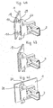
- the web-shaped holding device To mount the guide rail 3 on the fitting 2, the web-shaped holding device first inserted obliquely into the guide section 26, insofar as this is due to the inclined position of the web-shaped holding device 6 at all is possible ( Figure 2B). Once the holding device 6 within the guide section 26 jammed, the holding device with the guide rail must pass are pivoted on the side wall 24, so that the web-shaped holding device 6 is aligned parallel to the rear wall 22 and front wall 23. The Crosspieces 7 and 8 engage in the guide section 26.
- the assembled guide rail in the horizontal direction between a first end position at which the guide rail 3 abuts the front wall 23 with one leg (FIG. 3C) up to a second end position, in which the middle section 30 of the guide rail 3 rests against the side wall 24 (FIG. 3A).
- the front section of the holding device 6 In the second End position, the front section of the holding device 6 is still within the Guide section 26 arranged so that a movement of the guide rail 3 in Longitudinal direction is prevented.
- the guide rail 3 is without pivoting movement held captive on the fitting 2.
- the rear wall 22 is not continuous, so that a recess 19 is present between the side wall 24 and the rear wall 22.
- This is the side wall 24 is designed somewhat more flexibly and can also be insignificant during assembly be pushed backwards so that the web-shaped holding device 6 can be more easily inserted into the guide section 26.
- the fitting 2 is mounted on one Wall 1 shown.
- the guide rail 3 When mounting the guide rail 3 is already with the Fitting 2 connected. It is also possible to attach the fitting 2 to the wall 1 in advance to assemble and only then the web-shaped holding device 6 on the fitting 2 set.
- the pin 29 is with the flange portion 18 in an upper opening 10 and lower pin 29 is inserted into an opening 11 in the wall 1 and then pivoted so that the rear wall 22 abuts the wall 1.
- This Position is wall 1 between flange portion 18 and wall 22 held and the pin 29 can by a pulling movement in the direction of the longitudinal axis the guide rail 3 are not moved.
- the in Figs. 4A to 5C shown wall 1 is of small thickness. If walls are thicker used, the length of the pin 29 and, if necessary, the formation of the Holding section 18 or the diameter of the openings 10, 11 accordingly can be adjusted in order to be able to insert the pins 29 into the openings 10, 11.
- the fitting 2 is shown before assembly.
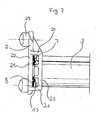
- the leadership section 26 is divided into individual chambers by webs 25, the Bars 25 do not reach up to the rear wall 22.
- the leadership section is further through the side walls 20 and 21 as well as the rear wall 22 and the front Wall 23 limited.
- the guide section 26 is for a large extent positive guidance of the webs 7 and 8 of the web-shaped holding device 6 designed.
- the webs 7 and 8 each have a profile 17, the cross section represents a curvature facing the front wall 23. Neighboring too the profiling 17 of the web 7 and 8 is each flat and lies on the rear wall 22. Part of the web 7 lies on the opposite side and 8 on the end face 25 and prevents the webs 7 or 8 in the direction the axis of the guide rail 3 are moved.
- the profiling 17 further achieved that the movement of the webs 7 and 8 each to the middle of the Guide section 26 is limited out, the webs 25 with an edge of the profiling 17. This limitation with the webs 25 further avoided that the web-shaped holding device 6 about an axis is rotated perpendicular to the sheet plane of Figure 7.
- the web-shaped holding device 6 has two webs 7 and 8. It is of course possible to have only one web or more than two Provide webs.
- the profiling 17 also serves to stiffen the web-shaped Holding device 6. If the profiling 17 is omitted, it will be useful, too to omit the recess 9 and to modify the webs 7 and 8 so that the holding device 6 receives the required stability. Then it can be useful to change the position and shape of the webs 25 to the project achieve the described purpose.
- the fitting 2 consists of a plastic and the guide rail 3 with the web-shaped holding device 6 made of metal. However, other materials can also be used be used.
Landscapes
- Drawers Of Furniture (AREA)
- Clamps And Clips (AREA)
Applications Claiming Priority (2)
| Application Number | Priority Date | Filing Date | Title |
|---|---|---|---|
| DE20210571U | 2002-07-09 | ||
| DE20210571U DE20210571U1 (de) | 2002-07-09 | 2002-07-09 | Vorrichtung zur Befestigung einer Führungsschiene an einer Wand |
Publications (1)
| Publication Number | Publication Date |
|---|---|
| EP1380231A1 true EP1380231A1 (fr) | 2004-01-14 |
Family
ID=7972975
Family Applications (1)
| Application Number | Title | Priority Date | Filing Date |
|---|---|---|---|
| EP03012455A Withdrawn EP1380231A1 (fr) | 2002-07-09 | 2003-05-30 | Dispositif de fixation d'un rail de guidage à une paroi |
Country Status (4)
| Country | Link |
|---|---|
| US (1) | US20040104651A1 (fr) |
| EP (1) | EP1380231A1 (fr) |
| CA (1) | CA2433305A1 (fr) |
| DE (1) | DE20210571U1 (fr) |
Cited By (1)
| Publication number | Priority date | Publication date | Assignee | Title |
|---|---|---|---|---|
| US10905238B1 (en) | 2019-11-12 | 2021-02-02 | Masterbrand Cabinets, Inc | Bracket for drawer slide rail |
Families Citing this family (13)
| Publication number | Priority date | Publication date | Assignee | Title |
|---|---|---|---|---|
| US7331644B2 (en) * | 2004-10-13 | 2008-02-19 | Mark Jeffrey Lowe | Stay-closed drawer slide with socket |
| US7625051B1 (en) * | 2004-11-05 | 2009-12-01 | Accuride International, Inc. | Drawer and drawer slide face-frame bracket adjuster |
| US20060226748A1 (en) * | 2005-04-08 | 2006-10-12 | Merillat Industries, Llc | Drawer guide support bracket |
| DE202008004100U1 (de) * | 2008-03-25 | 2009-08-06 | Paul Hettich Gmbh & Co. Kg | Teleskopierbare Auszugsführung |
| US8616664B2 (en) * | 2009-05-19 | 2013-12-31 | Tenn-Tex Plastics, Inc. | Inset undermounted bracket for drawer and tray slides in cabinetry |
| WO2013027285A1 (fr) * | 2011-08-24 | 2013-02-28 | 富士通株式会社 | Rail monté sur boîtier, plaque vierge et système de montage de bâti |
| US8876232B2 (en) | 2011-10-27 | 2014-11-04 | Rsi Home Products Management, Inc. | Drawer glide mechanism |
| US12193567B2 (en) | 2012-03-02 | 2025-01-14 | American Woodmark Management Company | Drawer glide mechanism |
| USD729611S1 (en) * | 2012-11-15 | 2015-05-19 | Fulterer U.S.A., Inc. | Bracket for drawer slide |
| US9211008B2 (en) * | 2014-01-22 | 2015-12-15 | King Slide Works Co., Ltd. | Slide assembly |
| US9375084B2 (en) | 2014-05-09 | 2016-06-28 | Rsi Home Products Management, Inc. | Drawer glide mechanism |
| DE202014106052U1 (de) * | 2014-12-15 | 2016-03-16 | Grass Gmbh | Vorrichtung zur Führung eines Schubelements und Kücheneinrichtung mit einer solchen Vorrichtung |
| USD904864S1 (en) * | 2017-12-22 | 2020-12-15 | Julius Blum Gmbh | Drawer synchronizing element |
Citations (2)
| Publication number | Priority date | Publication date | Assignee | Title |
|---|---|---|---|---|
| DE3832701A1 (de) | 1988-09-27 | 1990-03-29 | Lautenschlaeger Kg Karl | Befestigungsanordnung fuer die fuehrungsschiene einer ausziehfuehrung |
| US5636820A (en) * | 1995-05-12 | 1997-06-10 | Grass America, Inc. | Bracket for supporting a drawer guide in a furniture article |
Family Cites Families (5)
| Publication number | Priority date | Publication date | Assignee | Title |
|---|---|---|---|---|
| US5387033A (en) * | 1993-02-23 | 1995-02-07 | Grass America, Inc. | Laterally adjustable mounting bracket for use in a desk or cabinet drawer and with a drawer guide having a bent tongue |
| US5746490A (en) * | 1996-10-02 | 1998-05-05 | Grass America, Inc. | Drawer guide support bracket |
| US5823648A (en) * | 1997-04-10 | 1998-10-20 | Grass America, Inc. | Bracket for mounting a drawer guide |
| US6367900B1 (en) * | 2000-05-30 | 2002-04-09 | Hafele America Co. | Mounting bracket for the side rails of rear-mounted drawer slide assemblies |
| US6494550B1 (en) * | 2001-05-31 | 2002-12-17 | King Slide Works Co., Ltd. | Fixing base structure of a slide track |
-
2002
- 2002-07-09 DE DE20210571U patent/DE20210571U1/de not_active Expired - Lifetime
-
2003
- 2003-05-30 EP EP03012455A patent/EP1380231A1/fr not_active Withdrawn
- 2003-06-25 CA CA002433305A patent/CA2433305A1/fr not_active Abandoned
- 2003-07-08 US US10/614,077 patent/US20040104651A1/en not_active Abandoned
Patent Citations (2)
| Publication number | Priority date | Publication date | Assignee | Title |
|---|---|---|---|---|
| DE3832701A1 (de) | 1988-09-27 | 1990-03-29 | Lautenschlaeger Kg Karl | Befestigungsanordnung fuer die fuehrungsschiene einer ausziehfuehrung |
| US5636820A (en) * | 1995-05-12 | 1997-06-10 | Grass America, Inc. | Bracket for supporting a drawer guide in a furniture article |
Cited By (1)
| Publication number | Priority date | Publication date | Assignee | Title |
|---|---|---|---|---|
| US10905238B1 (en) | 2019-11-12 | 2021-02-02 | Masterbrand Cabinets, Inc | Bracket for drawer slide rail |
Also Published As
| Publication number | Publication date |
|---|---|
| DE20210571U1 (de) | 2003-03-06 |
| CA2433305A1 (fr) | 2004-01-09 |
| US20040104651A1 (en) | 2004-06-03 |
Similar Documents
| Publication | Publication Date | Title |
|---|---|---|
| DE3832701C2 (de) | Befestigungsanordnung für die Führungsschiene einer Ausziehführung | |
| AT404664B (de) | Vorrichtung zur befestigung der frontblende einer schublade an schubladenzargen | |
| DE3716923C2 (fr) | ||
| EP3760076A1 (fr) | Broche de raccordement pour parties de meuble | |
| EP3289925B1 (fr) | Support d'angle | |
| DE29613357U1 (de) | Befestigungsanordnung von Führungsschienen von Ausziehführungen | |
| DE8307469U1 (de) | Schubkasten aus kunststoff fuer moebel | |
| WO1994018870A1 (fr) | Ferrure de fixation pour les panneaux avant de tiroirs | |
| EP1084658B1 (fr) | Ensemble de glissières | |
| DE20210571U1 (de) | Vorrichtung zur Befestigung einer Führungsschiene an einer Wand | |
| WO2016050464A1 (fr) | Dispositif de guidage pour le guidage d'une porte coulissante et armoire de mobilier | |
| EP2168455B1 (fr) | Rail de guidage d'un guidage d'extraction de meuble | |
| DE102008011672B4 (de) | Kabelführungsvorrichtung | |
| WO2013087503A1 (fr) | Élément de fixation et grille latérale | |
| AT510773B1 (de) | Schubladenanordnung mit einer an einem Schubladenbehälter vormontierten Behältnisschiene | |
| DE19837367C2 (de) | Rahmenprofil für einen Schaltschrank | |
| WO2021110426A1 (fr) | Dispositif d'ombrage | |
| EP1568838A2 (fr) | Rail de guidage pour portes coulissantes ou portes coulissantes et pliantes | |
| WO2017072106A1 (fr) | Dispositif de guidage de portes coulissantes et meuble de rangement | |
| EP3852579A1 (fr) | Tiroir et unité constituée d'un guide de tiroir et d'un tiroir | |
| EP0927530A1 (fr) | Guide de sortie pour tiroirs | |
| AT395809B (de) | Ausziehfuehrung fuer schubladen u.dgl. | |
| DE202009002713U1 (de) | Gleitbeschlag | |
| DE102007009667B4 (de) | Profilkonstruktion | |
| EP2067906B1 (fr) | Système de connexion pour tiges de profil en forme de cannelure et agencement de connexion |
Legal Events
| Date | Code | Title | Description |
|---|---|---|---|
| PUAI | Public reference made under article 153(3) epc to a published international application that has entered the european phase |
Free format text: ORIGINAL CODE: 0009012 |
|
| AK | Designated contracting states |
Kind code of ref document: A1 Designated state(s): AT BE BG CH CY CZ DE DK EE ES FI FR GB GR HU IE IT LI LU MC NL PT RO SE SI SK TR |
|
| AX | Request for extension of the european patent |
Extension state: AL LT LV MK |
|
| AKX | Designation fees paid | ||
| REG | Reference to a national code |
Ref country code: DE Ref legal event code: 8566 |
|
| STAA | Information on the status of an ep patent application or granted ep patent |
Free format text: STATUS: THE APPLICATION IS DEEMED TO BE WITHDRAWN |
|
| 18D | Application deemed to be withdrawn |
Effective date: 20040715 |