EP3760076A1 - Broche de raccordement pour parties de meuble - Google Patents
Broche de raccordement pour parties de meuble Download PDFInfo
- Publication number
- EP3760076A1 EP3760076A1 EP20192834.8A EP20192834A EP3760076A1 EP 3760076 A1 EP3760076 A1 EP 3760076A1 EP 20192834 A EP20192834 A EP 20192834A EP 3760076 A1 EP3760076 A1 EP 3760076A1
- Authority
- EP
- European Patent Office
- Prior art keywords
- connecting pin
- fastening
- drawer
- wall
- front panel
- Prior art date
- Legal status (The legal status is an assumption and is not a legal conclusion. Google has not performed a legal analysis and makes no representation as to the accuracy of the status listed.)
- Granted
Links
Images



Classifications
-
- A—HUMAN NECESSITIES
- A47—FURNITURE; DOMESTIC ARTICLES OR APPLIANCES; COFFEE MILLS; SPICE MILLS; SUCTION CLEANERS IN GENERAL
- A47B—TABLES; DESKS; OFFICE FURNITURE; CABINETS; DRAWERS; GENERAL DETAILS OF FURNITURE
- A47B88/00—Drawers for tables, cabinets or like furniture; Guides for drawers
- A47B88/90—Constructional details of drawers
- A47B88/919—Accessories or additional elements for drawers, e.g. drawer lighting
- A47B88/931—Rails or rods mounted above the drawer walls, e.g. for stabilisation of the drawer or for suspension of the content
-
- A—HUMAN NECESSITIES
- A47—FURNITURE; DOMESTIC ARTICLES OR APPLIANCES; COFFEE MILLS; SPICE MILLS; SUCTION CLEANERS IN GENERAL
- A47B—TABLES; DESKS; OFFICE FURNITURE; CABINETS; DRAWERS; GENERAL DETAILS OF FURNITURE
- A47B88/00—Drawers for tables, cabinets or like furniture; Guides for drawers
- A47B88/90—Constructional details of drawers
- A47B88/941—Drawers being constructed from two or more parts
-
- A—HUMAN NECESSITIES
- A47—FURNITURE; DOMESTIC ARTICLES OR APPLIANCES; COFFEE MILLS; SPICE MILLS; SUCTION CLEANERS IN GENERAL
- A47B—TABLES; DESKS; OFFICE FURNITURE; CABINETS; DRAWERS; GENERAL DETAILS OF FURNITURE
- A47B88/00—Drawers for tables, cabinets or like furniture; Guides for drawers
- A47B88/90—Constructional details of drawers
- A47B88/944—Drawers characterised by the front panel
- A47B88/95—Drawers characterised by the front panel characterised by connection means for the front panel
-
- F—MECHANICAL ENGINEERING; LIGHTING; HEATING; WEAPONS; BLASTING
- F16—ENGINEERING ELEMENTS AND UNITS; GENERAL MEASURES FOR PRODUCING AND MAINTAINING EFFECTIVE FUNCTIONING OF MACHINES OR INSTALLATIONS; THERMAL INSULATION IN GENERAL
- F16B—DEVICES FOR FASTENING OR SECURING CONSTRUCTIONAL ELEMENTS OR MACHINE PARTS TOGETHER, e.g. NAILS, BOLTS, CIRCLIPS, CLAMPS, CLIPS OR WEDGES; JOINTS OR JOINTING
- F16B12/00—Jointing of furniture or the like, e.g. hidden from exterior
- F16B12/10—Jointing of furniture or the like, e.g. hidden from exterior using pegs, bolts, tenons, clamps, clips, or the like
- F16B12/12—Jointing of furniture or the like, e.g. hidden from exterior using pegs, bolts, tenons, clamps, clips, or the like for non-metal furniture parts, e.g. made of wood, of plastics
- F16B12/14—Jointing of furniture or the like, e.g. hidden from exterior using pegs, bolts, tenons, clamps, clips, or the like for non-metal furniture parts, e.g. made of wood, of plastics using threaded bolts or screws
-
- F—MECHANICAL ENGINEERING; LIGHTING; HEATING; WEAPONS; BLASTING
- F16—ENGINEERING ELEMENTS AND UNITS; GENERAL MEASURES FOR PRODUCING AND MAINTAINING EFFECTIVE FUNCTIONING OF MACHINES OR INSTALLATIONS; THERMAL INSULATION IN GENERAL
- F16B—DEVICES FOR FASTENING OR SECURING CONSTRUCTIONAL ELEMENTS OR MACHINE PARTS TOGETHER, e.g. NAILS, BOLTS, CIRCLIPS, CLAMPS, CLIPS OR WEDGES; JOINTS OR JOINTING
- F16B12/00—Jointing of furniture or the like, e.g. hidden from exterior
- F16B12/10—Jointing of furniture or the like, e.g. hidden from exterior using pegs, bolts, tenons, clamps, clips, or the like
- F16B12/12—Jointing of furniture or the like, e.g. hidden from exterior using pegs, bolts, tenons, clamps, clips, or the like for non-metal furniture parts, e.g. made of wood, of plastics
- F16B12/24—Jointing of furniture or the like, e.g. hidden from exterior using pegs, bolts, tenons, clamps, clips, or the like for non-metal furniture parts, e.g. made of wood, of plastics using separate pins, dowels, or the like
-
- F—MECHANICAL ENGINEERING; LIGHTING; HEATING; WEAPONS; BLASTING
- F16—ENGINEERING ELEMENTS AND UNITS; GENERAL MEASURES FOR PRODUCING AND MAINTAINING EFFECTIVE FUNCTIONING OF MACHINES OR INSTALLATIONS; THERMAL INSULATION IN GENERAL
- F16B—DEVICES FOR FASTENING OR SECURING CONSTRUCTIONAL ELEMENTS OR MACHINE PARTS TOGETHER, e.g. NAILS, BOLTS, CIRCLIPS, CLAMPS, CLIPS OR WEDGES; JOINTS OR JOINTING
- F16B12/00—Jointing of furniture or the like, e.g. hidden from exterior
- F16B12/44—Leg joints; Corner joints
- F16B12/46—Non-metal corner connections
-
- A—HUMAN NECESSITIES
- A47—FURNITURE; DOMESTIC ARTICLES OR APPLIANCES; COFFEE MILLS; SPICE MILLS; SUCTION CLEANERS IN GENERAL
- A47B—TABLES; DESKS; OFFICE FURNITURE; CABINETS; DRAWERS; GENERAL DETAILS OF FURNITURE
- A47B88/00—Drawers for tables, cabinets or like furniture; Guides for drawers
- A47B88/90—Constructional details of drawers
- A47B88/944—Drawers characterised by the front panel
- A47B88/95—Drawers characterised by the front panel characterised by connection means for the front panel
- A47B2088/953—Drawers characterised by the front panel characterised by connection means for the front panel fastening the front panel to a metal sheet side wall
-
- A—HUMAN NECESSITIES
- A47—FURNITURE; DOMESTIC ARTICLES OR APPLIANCES; COFFEE MILLS; SPICE MILLS; SUCTION CLEANERS IN GENERAL
- A47B—TABLES; DESKS; OFFICE FURNITURE; CABINETS; DRAWERS; GENERAL DETAILS OF FURNITURE
- A47B88/00—Drawers for tables, cabinets or like furniture; Guides for drawers
- A47B88/40—Sliding drawers; Slides or guides therefor
- A47B88/423—Fastening devices for slides or guides
-
- F—MECHANICAL ENGINEERING; LIGHTING; HEATING; WEAPONS; BLASTING
- F16—ENGINEERING ELEMENTS AND UNITS; GENERAL MEASURES FOR PRODUCING AND MAINTAINING EFFECTIVE FUNCTIONING OF MACHINES OR INSTALLATIONS; THERMAL INSULATION IN GENERAL
- F16B—DEVICES FOR FASTENING OR SECURING CONSTRUCTIONAL ELEMENTS OR MACHINE PARTS TOGETHER, e.g. NAILS, BOLTS, CIRCLIPS, CLAMPS, CLIPS OR WEDGES; JOINTS OR JOINTING
- F16B5/00—Joining sheets or plates, e.g. panels, to one another or to strips or bars parallel to them
- F16B5/0004—Joining sheets, plates or panels in abutting relationship
Definitions
- the invention further relates to an arrangement with a first furniture part in the form of a front panel and / or a second furniture part in the form of a drawer rail and / or a drawer wall and / or a wall element placed on the drawer wall and with a connecting pin of the type to be described.
- the invention relates to a set of drawers consisting of a connecting pin, a first drawer wall and / or a drawer rail and / or a second drawer wall, which has a lower height than the first drawer wall, a wall element being placed on the second drawer wall.
- connection system for furniture parts having a socket, a dowel which can be detachably connected to the socket and an expansion body for expanding the dowel.
- the socket can be inserted into a first bore of a first furniture part, a tapered neck of the dowel being able to be pushed into a recess in the socket and thereby the socket being locked in the first bore is.
- the dowel can also be inserted into a second bore in the second furniture part and can be expanded in this second bore by the expansion dowel, so that, overall, there is a firm connection between the two furniture parts.
- the object of the invention is to provide a connecting pin of the type mentioned at the beginning with various possible uses.
- the holding section of the connecting pin has a connecting piece facing the fastening section in the form of a projection or a recess for positively connecting the second furniture part to the connecting pin and a head part spaced apart over a neck in a longitudinal direction of the connecting pin, in one State in which the connecting pin is attached to the first furniture part via the fastening section, optionally at least two different second furniture parts can be connected positively to the connecting pin by the connecting piece and / or non-positively connected to the connecting pin by the head part.
- the connecting pin with the connecting piece and the head part it is possible that at least two differently designed second furniture parts, for example a first drawer wall, a drawer rail and / or a wall element placed on a second drawer wall, optionally form-fitting and / or force-fitting with a first Drawer wall, for example in the form of a front panel, can be connected.
- second furniture parts for example a first drawer wall, a drawer rail and / or a wall element placed on a second drawer wall, optionally form-fitting and / or force-fitting with a first Drawer wall, for example in the form of a front panel, can be connected.
- the connecting piece of the connecting pin can thus comprise at least one projection or at least one recess through which a form-fitting connection between the connecting pin and the second furniture part can be established with the aid of a cooperating counter-contour of the second furniture part. If necessary, this form-fitting connection can also be brought about with the aid of a further component.
- the form-fit connection can also be secured by the force of a spring element, whereby the load-bearing capacity of the form-fit connection can be additionally increased.
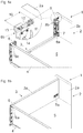
- Fig. 1a shows a part of a first drawer 1 with a drawer bottom 5, a first furniture part 2 in the form of a front panel 2a, a second furniture part 3 in the form of a drawer wall 3a and a rear wall 4.
- the drawer wall 3a is a hollow chamber profile with an inner profile wall and an outer profile wall formed, the hollow profile in Fig. 1a is hidden for improved visualization.
- the drawer wall 3a has a rear wall holder 6 with projections 6a, which in the assembled state in corresponding openings 16 ( Fig. 3a ) engage the rear wall 4.
- the drawer wall 3a has a first fastening device 8a, which - as per se from the EP 0 740 917 A1 known - can be releasably latched to a holding part 7 to be attached to the front panel 2a.
- the drawer wall 3a further comprises a second fastening device 8b, which in the assembly position occupies a higher position than the first fastening device 8a.
- the second fastening device 8b can be connected positively and / or non-positively to a preassembled connecting pin 9 to be fastened to the front panel 2a.
- the in Fig. 1a The circled area is shown to the side in an enlarged view.
- the connecting pin 9 is via a fastening section 19 ( Fig. 4 ) to be mounted on the rear side of the front panel 2a and has a holding section 10 which comprises a connecting piece 11 and a head part 13 connected via a neck 12.
- the connecting piece 11 is not used in this embodiment.
- Figure 1b shows the design of the drawer 1 according to Fig. 1a , the drawer wall 3a, which is designed as a hollow chamber profile, is displayed.
- the drawer wall 3 a can have essentially the same height as the rear wall 4. This is a relatively high drawer wall 3 a, as a result of which the receiving volume of the drawer 1 is increased.
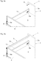
- Fig. 2a shows a portion of a second drawer 1 with a drawer bottom 5, a first furniture part 2 in the form of a front panel 2a, a side drawer wall 15 and a rear wall 4.
- This drawer wall 15 can be less than half the height of the one in Figure 1b
- the drawer wall 15 is again designed as a hollow chamber profile with an inner profile wall and an outer profile wall and has a rear wall holder 6 with projections 6a, which in the assembled state in corresponding openings 16 ( Fig. 3a ) engage the rear wall 4.
- the drawer wall 15 includes - as in the Figures 1a, 1b shown - a first fastening device 8a, which can be releasably locked to a holding part 7 to be fastened to the front panel 2a.
- the connecting pin 9, which can be connected to a second furniture part 3 - here with a drawer rail 3b arranged above the drawer wall 15 - is to be mounted on the back of the front panel 2a.
- the mounted position of the drawer rail 3b is in Figure 2b shown.
- one and the same connecting pin 9 is both connected to the in Figure 1b shown drawer wall 3a as well as with the in Figure 2b shown drawer railing 3b connectable.
- Fig. 3a shows a third drawer 1 with the drawer bottom 5, the rear wall 4, the front panel 2a and a drawer wall 15 designed as a hollow chamber profile, which is the same height as the lower drawer wall 15 according to FIG Figures 2a, 2b may have.
- the drawer wall 15 has in the front end area a first fastening device 8a for releasable locking with the holding part 7 to be fastened to the front panel 2a ( Fig. 1a ) on.
- the second furniture part 3 is formed in this embodiment by a wall element 3c, which - optionally forming a Gap - is placed on the side wall of the drawer 15.
- the wall element 3c can be designed as a hollow chamber profile with an inner and an outer profile wall.
- FIG. 3a only the second fastening device 8b is shown of the wall element 3c.
- the wall element 3c To assemble the wall element 3c, it is first pushed onto the connecting pin 9 with a front face and then placed on the drawer wall 15 by a downward vertical movement, with a counter-contour 17 of the wall element 3c being insertable into the connecting piece 11 of the connecting pin 9. In this way, the wall element 3c can be positively connected to the connecting pin 9 in the assembled position.
- the wall element 3c has at least one counter-stop 18 which, in the assembled position, rests against the underside of the head part 13 and fixes the wall element 3c in a force-locking manner in the longitudinal direction.
- Figure 3b shows the wall element 3c mounted on the drawer 1, the top side of the wall element 3c being flush with the top side of the rear wall.
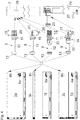
- Fig. 4 shows a view of various second furniture parts 3 in the form of the high drawer wall 3a, the drawer rail 3b arranged above the lower drawer wall 15 and the wall element 3c placed on the lower drawer wall 15.
- the high drawer wall 3a and the two lower drawer walls 15 each have a first fastening device 8a in the front end area, each of which is connected to the holding part 7 to be fastened to the front panel 3a ( Fig. 1a ) is releasably lockable.
- These first fastening devices 8a are each arranged close to the bottom (ie in a position adjacent to the drawer bottom 5).
- second fastening devices 8b Located above these first fastening devices 8a are second fastening devices 8b, which can each be locked with four different types of connecting pins 9 in a form-fitting and / or force-fitting manner.
- the first (uppermost) of the four connecting pins 9 shown comprises a head part 13, a neck 12, a connecting piece 11 and a Fastening section 19 in the form of a dowel 20, which together with the holding section 10 ( Fig. 1a ) is formed in one piece.
- the dowel 20 can be pressed into a bore 26 of the first furniture part 2.
- the fastening section 19 has a thread 21 which can be screwed into the first furniture part 2 for fastening the connecting pin 9.
- the dowel 20 is connected to the holding section 10 ( Fig. 1a ) pivotally connected via a hinge axis 22, the connecting pin 9 having an expanding part 23 for expanding the dowel 20, the expanding part 23 being movable about the hinge axis 22 by a pivoting movement of the holding section 10, so that the dowel 20 can be moved into an expanded position and thus within the bore 26 of the first furniture part 2 can be locked.
- the connecting pin 9 having an expanding part 23 for expanding the dowel 20, the expanding part 23 being movable about the hinge axis 22 by a pivoting movement of the holding section 10, so that the dowel 20 can be moved into an expanded position and thus within the bore 26 of the first furniture part 2 can be locked.
- Such a functionality of an expandable dowel 20 is for example in the EP 0 698 357 A1 disclosed by the applicant.
- the head part 13 can be detachably connected to the fastening section 19, preferably by a snap connection 24.
- the connecting pin 9 can also be fastened to a front panel 2a (for example an internal pull-out) by a pivotable lever 25, the lever 25 engaging in the connecting piece 11 in the assembled position of the connecting pin 9 and thus the connecting pin 9 through Form fit locked on the front panel 2a.
- Fig. 5 shows an embodiment of a connecting pin 9 in a perspective view.
- the connecting pin 9 has a fastening section 19, for example with a dowel 20, for fastening to the first furniture part 2.
- the holding section 10 is provided for connection to the second furniture part 3 and comprises a connecting piece 11 for the positive connection of the second furniture part 3 with the connecting pin 9 and a head part 13 spaced apart in a longitudinal direction (L) via a neck 12, with optionally at least two different second ones Furniture parts 3 can be connected to the connecting pin 9 in a form-fitting manner by the connecting piece 11 and / or by the head part 13 in a force-fitting manner.
- the connecting piece 11 has a first, preferably designed as a web, Projection 27a and at least one second, preferably designed as a web, projection 27b, the first projection 27a and the second projection 27b each protruding transversely from the connecting pin 9 and in the longitudinal direction (L) of the connecting pin 9 through a recess 27c, for example in the form of a cylindrical portion, are spaced apart. It can be provided that the first projection 27a and / or the second projection 27b and / or the cylindrical section and / or the head part 13 is or are rotationally symmetrical about the longitudinal direction (L), whereby the connecting pin 9 is particularly easy to manufacture.
- the cylindrical section can have a smaller diameter than the first projection 27a and the second projection 27b.
- the first projection 27a and / or the second projection 27b can be configured as an annular web and the recess 27c can be configured as an annular groove.
- the first projection 27a fixes the second furniture part 3 in a direction transverse to the longitudinal direction (L), while the second furniture part 3 is fixed relative to the connecting pin 9 through the recess 27c in the longitudinal direction (L).
- the head part 13 for the frictional connection with the second furniture part 3 has a larger diameter than the neck 12, a stop surface 13a that preferably runs at right angles to the longitudinal direction (L), an annular section 13b and an inclined surface 13c running towards the tip of the head part 13 .
- the head part 13 can be provided with a tool holder 13d, whereby a thread 21 of the connecting pin 9 can be screwed into the first furniture part 2 by rotating the tool holder 13d by means of a tool.
- the arrows (F) shown each identify those areas of the holding section 10 at which the non-positive and positive connection are effective in the assembled state of the second furniture part 3.
- Figure 6a shows the high side wall 3a, which has two fastening devices 8a, 8b spaced from one another in the height direction.
- the second (upper) fastening device 8b can be releasably locked with the connecting pin 9.
- Figure 6b shows an enlarged detailed view of the second fastening device 8b according to FIG Figure 6a which comprises at least one resilient or spring-loaded locking element 14, which can be releasably connected, preferably latched, to the holding section 10 of the connecting pin 9.
- the connecting pin 9 can be inserted into the second fastening device 8b in an insertion direction 29, the locking element 14 being movable against its resilient effect in a direction transverse to the insertion direction 29 through an entry of the connecting pin 9 into the second fastening device 8b and the connecting pin 9 can be locked automatically by a continued movement in the insertion direction 29 by the resilient effect of the locking element 14.
- the locking element 14 is mounted pivotably about the axis of rotation 28 and is pretensioned by a spring element (not shown), with an inclined surface 14a of the locking element 14 cooperating with the inclined surface 13c of the head part 13 when the connecting pin 9 is inserted, whereby the locking element 14 about the axis of rotation 28 in the Tilted counterclockwise and the connecting pin 9 can be locked by the subsequent snapping open of the locking element 14.
- the locking element 14 rests against the stop surface 13a of the head part 13, as a result of which the connecting pin 9 is fixed in a non-positive manner.
- Figure 6c shows the drawer rail 3b, which has a second fastening device 8b for fastening the connecting pin 9 in the front end region.
- the second fastening device 8b is shown enlarged.
- the locking element 14 has two spring tongues which, when the connecting pin 9 is inserted into the second fastening device 8b, are elastically bendable against their resilient effect in a direction running transversely to the insertion direction 29, with continued movement of the connecting pin 9 in Insertion direction 29 snap back the said spring tongues and thereby fix the connecting pin 9 in a non-positive manner.
- the free ends of the spring tongues rest against the stop surface 13a of the head part 13.
- Figure 6e shows the wall element 3c placed on the drawer wall 15, which has a second fastening device 8b in the front end region.
- Fig. 6f shows the second fastening device 8b in an enlarged view.
- the wall element 3c is pushed with one end face onto the connecting pin 9 and then pushed onto the holding section 10 of the connecting pin 9 from above (ie by a downward vertical movement of the wall part 3c towards the drawer wall 15), with a mating contour 17 of the wall part 3c can be introduced into the connecting piece 11 of the connecting pin 9 and thus the positive fit between the wall element 3c and the connecting pin 9 is established.
- the counter attacks 18 see also Fig.
- the stop surface 13a of the head part 13 can rest on the stop surface 13a of the head part 13 or possibly be slightly spaced from the stop surface 13a. For example, if a person pulls jerkily on the front panel 2a of the drawer 1, the stop surface 13a of the connecting pin 9 strikes the counter-stops 18 of the wall part 3c, preventing the connecting pin 9 from slipping out of the second fastening device 8b in such an overload situation.
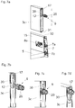
- Figure 7a shows the front end area of a lower drawer wall 15 and the wall element 3c to be arranged thereon.
- the first (lower) fastening device 8a of the drawer wall 15 can be releasably latched to the holding part 7 which is to be fastened to the rear of the front panel 2a and which has two fastening dowels 7a, 7b spaced apart in the height direction.
- An opening 32 is provided on the top of the drawer wall 15, into which the wall element 3c can be suspended via a hook 31 is.
- the wall element 3c has a keyhole 30 on its front side, through which the slightly inclined wall element 3c can be pushed onto the preassembled connecting pin 9.
- the assembly of the wall element 3c is in the Figures 7b-7d shown.
Landscapes
- Engineering & Computer Science (AREA)
- General Engineering & Computer Science (AREA)
- Mechanical Engineering (AREA)
- Drawers Of Furniture (AREA)
- Connection Of Plates (AREA)
- Furniture Connections (AREA)
Applications Claiming Priority (3)
| Application Number | Priority Date | Filing Date | Title |
|---|---|---|---|
| ATA50137/2017A AT518790B1 (de) | 2017-02-21 | 2017-02-21 | Verbindungsstift für Möbelteile |
| EP18707223.6A EP3585211B1 (fr) | 2017-02-21 | 2018-02-08 | Arrangement avec des pieces de fournitures et un element de connection |
| PCT/AT2018/060034 WO2018152557A1 (fr) | 2017-02-21 | 2018-02-08 | Tige de liaison destinée à des éléments de meuble |
Related Parent Applications (1)
| Application Number | Title | Priority Date | Filing Date |
|---|---|---|---|
| EP18707223.6A Division EP3585211B1 (fr) | 2017-02-21 | 2018-02-08 | Arrangement avec des pieces de fournitures et un element de connection |
Publications (2)
| Publication Number | Publication Date |
|---|---|
| EP3760076A1 true EP3760076A1 (fr) | 2021-01-06 |
| EP3760076B1 EP3760076B1 (fr) | 2023-08-23 |
Family
ID=60996861
Family Applications (2)
| Application Number | Title | Priority Date | Filing Date |
|---|---|---|---|
| EP18707223.6A Active EP3585211B1 (fr) | 2017-02-21 | 2018-02-08 | Arrangement avec des pieces de fournitures et un element de connection |
| EP20192834.8A Active EP3760076B1 (fr) | 2017-02-21 | 2018-02-08 | Set de tiroir comprenant trois cotés différents |
Family Applications Before (1)
| Application Number | Title | Priority Date | Filing Date |
|---|---|---|---|
| EP18707223.6A Active EP3585211B1 (fr) | 2017-02-21 | 2018-02-08 | Arrangement avec des pieces de fournitures et un element de connection |
Country Status (9)
| Country | Link |
|---|---|
| US (1) | US10966523B2 (fr) |
| EP (2) | EP3585211B1 (fr) |
| JP (1) | JP6840258B2 (fr) |
| CN (1) | CN110300531B (fr) |
| AT (1) | AT518790B1 (fr) |
| ES (2) | ES2963459T3 (fr) |
| MY (1) | MY196776A (fr) |
| TW (1) | TWI663342B (fr) |
| WO (1) | WO2018152557A1 (fr) |
Families Citing this family (17)
| Publication number | Priority date | Publication date | Assignee | Title |
|---|---|---|---|---|
| AT521512B1 (de) | 2018-10-05 | 2020-02-15 | Blum Gmbh Julius | Befestigungsvorrichtung zum lösbaren Befestigen einer Frontblende an einer Schublade |
| CN109915445B (zh) * | 2019-03-01 | 2024-05-14 | 黄勇 | 一种家具连接件及家具锁紧装置 |
| CN110742391A (zh) * | 2019-11-04 | 2020-02-04 | 泰山学院 | 一种桌腿长度调节装置 |
| DE202019106842U1 (de) * | 2019-12-09 | 2019-12-18 | Häfele Berlin Gmbh & Co Kg | Verbindungsbolzen und zugehöriger Verbindungsbeschlag |
| US11898584B2 (en) | 2020-02-07 | 2024-02-13 | Hni Technologies Inc. | Tool-less fastening system |
| TWI806690B (zh) * | 2022-07-04 | 2023-06-21 | 川湖科技股份有限公司 | 傢俱及其傢俱組件 |
| TWI806689B (zh) * | 2022-07-04 | 2023-06-21 | 川湖科技股份有限公司 | 傢俱及其傢俱組件 |
| TWI806691B (zh) * | 2022-07-04 | 2023-06-21 | 川湖科技股份有限公司 | 傢俱及其傢俱組件 |
| CN117432692A (zh) * | 2022-07-12 | 2024-01-23 | 川湖科技股份有限公司 | 家具及其家具组件 |
| CN117432693A (zh) * | 2022-07-12 | 2024-01-23 | 川湖科技股份有限公司 | 家具及其家具组件 |
| AT17942U1 (de) * | 2022-07-21 | 2023-08-15 | Blum Gmbh Julius | Schubladenseitenwand für eine Schublade |
| JP2024073919A (ja) * | 2022-11-18 | 2024-05-30 | タキゲン製造株式会社 | 溝付き柱材用取り付け部材及びその締結具 |
| TWI838155B (zh) * | 2023-03-06 | 2024-04-01 | 川湖科技股份有限公司 | 傢俱及其傢俱組件 |
| TWI843467B (zh) * | 2023-03-06 | 2024-05-21 | 川湖科技股份有限公司 | 傢俱及其傢俱組件 |
| TWI843468B (zh) * | 2023-03-06 | 2024-05-21 | 川湖科技股份有限公司 | 傢俱及其傢俱組件 |
| CN116538174B (zh) * | 2023-04-04 | 2025-12-16 | 中国科学院工程热物理研究所 | 一种金属与复合纤维材料的连接结构及加工方法 |
| USD1074417S1 (en) * | 2023-09-25 | 2025-05-13 | Yangjiang Yugongfang Home Furnishings Co., Ltd | Furniture connector |
Citations (11)
| Publication number | Priority date | Publication date | Assignee | Title |
|---|---|---|---|---|
| FR2106883A5 (fr) * | 1970-09-28 | 1972-05-05 | Blanc Lucien | |
| DE2546749A1 (de) * | 1975-10-18 | 1977-04-28 | Heinze Fa R | Beschlag zum loesbaren verbinden zweier bauteile, insbesondere zweier senkrecht aufeinanderstossender plattenfoermiger bauteile |
| DE29518690U1 (de) * | 1994-12-07 | 1996-02-15 | Julius Blum Ges.m.b.H., Höchst | Möbelbeschlag, insbesondere Verbindungsbeschlag |
| EP0698357A1 (fr) | 1994-08-26 | 1996-02-28 | Julius Blum Gesellschaft m.b.H. | Accessoire pour meubles, en particulier élément d'assemblage |
| EP0740917A1 (fr) | 1993-09-21 | 1996-11-06 | Julius Blum Gesellschaft m.b.H. | Dispositif pour fixer le panneau avant de tiroir, en particulier tiroir à double paroi, sur les parois latérales |
| US6120226A (en) * | 1999-07-09 | 2000-09-19 | Grass Gmbh | Railing fastener for drawer |
| DE10229300B3 (de) | 2002-06-29 | 2004-03-25 | Werthmüller Systeme Geisa GmbH & Co.KG | Verbindungssystem für Bauteile, insbesondere für Möbelteile |
| EP1516561A1 (fr) * | 2003-09-18 | 2005-03-23 | Grass AG | Tiroir doté de parois supérieurs |
| DE202009012750U1 (de) * | 2009-09-19 | 2011-02-10 | Hettich-Heinze Gmbh & Co. Kg | Dübelbolzen einer Verbindungsvorrichtung |
| EP2868228A1 (fr) * | 2013-10-31 | 2015-05-06 | Guangdong Taiming Metal Products Co., Ltd. | Structure de tige de traction pour tiroir |
| DE202016101285U1 (de) | 2015-03-16 | 2016-03-18 | Julius Blum Gmbh | Vorrichtung zur Montage eines Möbelbeschlages |
Family Cites Families (34)
| Publication number | Priority date | Publication date | Assignee | Title |
|---|---|---|---|---|
| FR1574425A (fr) * | 1968-07-04 | 1969-07-11 | ||
| DE3123185C2 (de) * | 1981-06-11 | 1984-07-26 | Arturo Salice S.P.A., Novedrate, Como | Verbindungsbeschlag |
| DE3127795C2 (de) | 1981-07-14 | 1985-08-29 | Arturo Salice S.P.A., Novedrate, Como | Verbindungsbeschlag |
| JPS58151705A (ja) | 1982-03-05 | 1983-09-09 | Mitsubishi Electric Corp | 導波管形スロツトアレイアンテナ |
| JPS58151705U (ja) * | 1982-04-06 | 1983-10-11 | 有限会社遠藤製作所 | 板状素材等の接続具 |
| JPS5920012A (ja) | 1982-07-17 | 1984-02-01 | ロバ−ト・ミカエル・ネルソン | 液面制御装置 |
| JPS5920012U (ja) * | 1982-07-28 | 1984-02-07 | 株式会社ドリ−ム総合研究所 | 組立収納家具における額縁装着金具 |
| FR2559557A1 (fr) * | 1984-02-09 | 1985-08-16 | Artech | Dispositif de maintien en trois dimensions d'assemblages |
| JPH0730487B2 (ja) | 1986-12-19 | 1995-04-05 | 帝人株式会社 | スパンライク複合嵩高糸 |
| AT391063B (de) * | 1987-01-08 | 1990-08-10 | Blum Gmbh Julius | Verbindungsbeschlag zur befestigung der reling einer schublade |
| US4886326A (en) * | 1988-01-29 | 1989-12-12 | Tetrad Marketing/Sales Ltd. | Interlock system for ready to assemble furniture, and furniture incorporating such system |
| US5403109A (en) * | 1993-06-09 | 1995-04-04 | Hon Industries Inc. | Fastening device for furniture construction and method of manufacture |
| DE59404139D1 (de) | 1993-07-28 | 1997-10-30 | Blum Gmbh Julius | Vorrichtung zur Befestigung der Frontblende einer Schublade an Schubladenzargen |
| GB2305226B (en) * | 1993-12-23 | 1997-07-16 | Titus Int Plc | Joint forming device |
| JP2002106525A (ja) * | 2000-09-27 | 2002-04-10 | Matsushita Electric Works Ltd | パネル接合構造とその構造を有するキャビネット |
| US20070160418A1 (en) * | 2006-01-10 | 2007-07-12 | Boyce Lo | Quick assembly bolt jacket |
| CN201534973U (zh) * | 2009-10-20 | 2010-07-28 | 江苏江达生态科技有限公司 | 预埋式真空固结堆场 |
| DE102010037281A1 (de) * | 2010-09-02 | 2012-03-08 | Paul Hettich Gmbh & Co. Kg | Möbelauszugsteil |
| AT510906A1 (de) * | 2011-01-03 | 2012-07-15 | Blum Gmbh Julius | Reling für ein bewegbares möbelteil |
| AT13522U1 (de) * | 2012-06-12 | 2014-02-15 | Blum Gmbh Julius | Schubladenreling |
| DE202013011421U1 (de) * | 2013-12-20 | 2015-03-23 | Grass Gmbh | Schubladenfrontanbindungselnheit |
| USD799313S1 (en) * | 2015-05-15 | 2017-10-10 | Häfele GmbH & Co KG | Screw |
| CN104895888B (zh) * | 2015-05-26 | 2017-03-08 | 中国石油天然气股份有限公司 | 一种驴头连接销 |
| DE102015110561A1 (de) * | 2015-07-01 | 2017-01-05 | Form Orange Produktentwicklung | Schublade mit einer Bodenplatte, einer Blende, einer Rückwand und zwei Seitenwänden, die fest miteinander verbunden sind |
| CN105054625B (zh) * | 2015-08-06 | 2018-08-03 | 伍志勇 | 家具抽屉的前面板与侧板连接结构 |
| DE202015008847U1 (de) * | 2015-12-22 | 2017-03-23 | Grass Gmbh | Befestigungsvorrichtung |
| US10377020B2 (en) * | 2017-03-15 | 2019-08-13 | International Business Machines Corporation | Fastener head adapter |
| DE202017102763U1 (de) * | 2017-05-09 | 2017-06-09 | Anton Schneider Gmbh & Co Kg | Frontblenden-Verbindungsbeschlag |
| DE202017003832U1 (de) * | 2017-07-19 | 2018-10-22 | Grass Gmbh | Vorrichtung zur Verbindung einer Front mit einer Zarge |
| AT520788B1 (de) * | 2017-12-21 | 2023-03-15 | Blum Gmbh Julius | Schubladenanordnung |
| AT18053U1 (de) * | 2017-12-21 | 2023-12-15 | Blum Gmbh Julius | Relingstrebe für eine Schublade |
| JP1627527S (ja) * | 2017-12-22 | 2019-03-25 | 引き出し用締結具 | |
| USD887259S1 (en) * | 2017-12-22 | 2020-06-16 | Julius Blum Gmbh | Fastening device |
| AT521512B1 (de) * | 2018-10-05 | 2020-02-15 | Blum Gmbh Julius | Befestigungsvorrichtung zum lösbaren Befestigen einer Frontblende an einer Schublade |
-
2017
- 2017-02-21 AT ATA50137/2017A patent/AT518790B1/de active
-
2018
- 2018-02-08 EP EP18707223.6A patent/EP3585211B1/fr active Active
- 2018-02-08 ES ES20192834T patent/ES2963459T3/es active Active
- 2018-02-08 WO PCT/AT2018/060034 patent/WO2018152557A1/fr not_active Ceased
- 2018-02-08 CN CN201880012742.2A patent/CN110300531B/zh active Active
- 2018-02-08 EP EP20192834.8A patent/EP3760076B1/fr active Active
- 2018-02-08 JP JP2019545241A patent/JP6840258B2/ja active Active
- 2018-02-08 MY MYPI2019004315A patent/MY196776A/en unknown
- 2018-02-08 ES ES18707223T patent/ES2832575T3/es active Active
- 2018-02-21 TW TW107105717A patent/TWI663342B/zh active
-
2019
- 2019-07-24 US US16/521,151 patent/US10966523B2/en active Active
Patent Citations (11)
| Publication number | Priority date | Publication date | Assignee | Title |
|---|---|---|---|---|
| FR2106883A5 (fr) * | 1970-09-28 | 1972-05-05 | Blanc Lucien | |
| DE2546749A1 (de) * | 1975-10-18 | 1977-04-28 | Heinze Fa R | Beschlag zum loesbaren verbinden zweier bauteile, insbesondere zweier senkrecht aufeinanderstossender plattenfoermiger bauteile |
| EP0740917A1 (fr) | 1993-09-21 | 1996-11-06 | Julius Blum Gesellschaft m.b.H. | Dispositif pour fixer le panneau avant de tiroir, en particulier tiroir à double paroi, sur les parois latérales |
| EP0698357A1 (fr) | 1994-08-26 | 1996-02-28 | Julius Blum Gesellschaft m.b.H. | Accessoire pour meubles, en particulier élément d'assemblage |
| DE29518690U1 (de) * | 1994-12-07 | 1996-02-15 | Julius Blum Ges.m.b.H., Höchst | Möbelbeschlag, insbesondere Verbindungsbeschlag |
| US6120226A (en) * | 1999-07-09 | 2000-09-19 | Grass Gmbh | Railing fastener for drawer |
| DE10229300B3 (de) | 2002-06-29 | 2004-03-25 | Werthmüller Systeme Geisa GmbH & Co.KG | Verbindungssystem für Bauteile, insbesondere für Möbelteile |
| EP1516561A1 (fr) * | 2003-09-18 | 2005-03-23 | Grass AG | Tiroir doté de parois supérieurs |
| DE202009012750U1 (de) * | 2009-09-19 | 2011-02-10 | Hettich-Heinze Gmbh & Co. Kg | Dübelbolzen einer Verbindungsvorrichtung |
| EP2868228A1 (fr) * | 2013-10-31 | 2015-05-06 | Guangdong Taiming Metal Products Co., Ltd. | Structure de tige de traction pour tiroir |
| DE202016101285U1 (de) | 2015-03-16 | 2016-03-18 | Julius Blum Gmbh | Vorrichtung zur Montage eines Möbelbeschlages |
Also Published As
| Publication number | Publication date |
|---|---|
| US10966523B2 (en) | 2021-04-06 |
| CN110300531B (zh) | 2022-03-08 |
| TW201835458A (zh) | 2018-10-01 |
| JP2020509308A (ja) | 2020-03-26 |
| US20190343279A1 (en) | 2019-11-14 |
| EP3760076B1 (fr) | 2023-08-23 |
| ES2963459T3 (es) | 2024-03-27 |
| AT518790B1 (de) | 2018-01-15 |
| TWI663342B (zh) | 2019-06-21 |
| EP3585211A1 (fr) | 2020-01-01 |
| WO2018152557A1 (fr) | 2018-08-30 |
| EP3585211B1 (fr) | 2020-09-09 |
| AT518790A4 (de) | 2018-01-15 |
| CN110300531A (zh) | 2019-10-01 |
| JP6840258B2 (ja) | 2021-03-10 |
| MY196776A (en) | 2023-05-03 |
| ES2832575T3 (es) | 2021-06-10 |
Similar Documents
| Publication | Publication Date | Title |
|---|---|---|
| EP3585211B1 (fr) | Arrangement avec des pieces de fournitures et un element de connection | |
| DE602004001734T2 (de) | Ein Befestigungselement zur Verbindung von an einem Trägerteil | |
| EP3478533B1 (fr) | Dispositif de réglage en longueur et siège de véhicule | |
| AT503418A4 (de) | Schublade mit wenigstens einer hölzernen schubladenseitenwand | |
| AT511905A1 (de) | Schublade | |
| EP3344841A1 (fr) | Dispositif de protection des doigts côté paumelle | |
| WO2018204956A1 (fr) | Commande de meuble à moteur | |
| DE29818651U1 (de) | Blendenbefestigungsvorrichtung für Schubladen | |
| EP4245954A2 (fr) | Chariot de guidage pour le montage mobile d'une partie de meuble | |
| WO1989005387A1 (fr) | Plaque de montage de charnieres de meubles | |
| DE102016117717A1 (de) | Befestigungseinrichtung für ein wandhängendes Sanitärobjekt, Befestigungsanordnung und Verfahren zur Montage eines wandhängenden Sanitärobjekts | |
| EP2420685A1 (fr) | Connecteur de raccordement de rainures profilées ainsi qu'agencement doté de ce type de connecteur | |
| DE102008044922A1 (de) | Vorrichtung und Verfahren zur Montage einer Führungsschienenanordnung | |
| WO2013087375A1 (fr) | Élément de fixation et grille latérale | |
| WO2019193043A1 (fr) | Élément de fixation par clip | |
| EP3745919B1 (fr) | Système | |
| EP3773074B1 (fr) | Systeme de tiroir comprenant un rail sur lequel differents types de tiroirs peuvent etre installes | |
| DE102016117714A1 (de) | Befestigungseinrichtung für ein wandhängendes Sanitärobjekt, Befestigungsanordnung und Verfahren zur Demontage eines wandhängenden Sanitärobjekts | |
| EP3369946B1 (fr) | Cheville plate et procédé de montage d'une cheville plate dans une paroi | |
| DE19707741A1 (de) | Möbelscharnier | |
| DE2641606C2 (de) | Wandkonstruktion für Kabinen, insbesondere für Sanitärkabinen | |
| EP1428941B1 (fr) | Dispositif de fixation d'un article sanitaire | |
| EP1479316A1 (fr) | Tiroir d'armoire avec moyens de guidage monté sur un coté | |
| EP2116800B1 (fr) | Appareil de refroidissement et élément de montage correspondant pour la plaque de recouvrement de celui-ci | |
| DE10324662B4 (de) | Griffbeschlag |
Legal Events
| Date | Code | Title | Description |
|---|---|---|---|
| PUAI | Public reference made under article 153(3) epc to a published international application that has entered the european phase |
Free format text: ORIGINAL CODE: 0009012 |
|
| STAA | Information on the status of an ep patent application or granted ep patent |
Free format text: STATUS: THE APPLICATION HAS BEEN PUBLISHED |
|
| AC | Divisional application: reference to earlier application |
Ref document number: 3585211 Country of ref document: EP Kind code of ref document: P |
|
| AK | Designated contracting states |
Kind code of ref document: A1 Designated state(s): AL AT BE BG CH CY CZ DE DK EE ES FI FR GB GR HR HU IE IS IT LI LT LU LV MC MK MT NL NO PL PT RO RS SE SI SK SM TR |
|
| STAA | Information on the status of an ep patent application or granted ep patent |
Free format text: STATUS: REQUEST FOR EXAMINATION WAS MADE |
|
| 17P | Request for examination filed |
Effective date: 20210702 |
|
| RBV | Designated contracting states (corrected) |
Designated state(s): AL AT BE BG CH CY CZ DE DK EE ES FI FR GB GR HR HU IE IS IT LI LT LU LV MC MK MT NL NO PL PT RO RS SE SI SK SM TR |
|
| GRAP | Despatch of communication of intention to grant a patent |
Free format text: ORIGINAL CODE: EPIDOSNIGR1 |
|
| STAA | Information on the status of an ep patent application or granted ep patent |
Free format text: STATUS: GRANT OF PATENT IS INTENDED |
|
| INTG | Intention to grant announced |
Effective date: 20230327 |
|
| P01 | Opt-out of the competence of the unified patent court (upc) registered |
Effective date: 20230523 |
|
| GRAS | Grant fee paid |
Free format text: ORIGINAL CODE: EPIDOSNIGR3 |
|
| GRAA | (expected) grant |
Free format text: ORIGINAL CODE: 0009210 |
|
| STAA | Information on the status of an ep patent application or granted ep patent |
Free format text: STATUS: THE PATENT HAS BEEN GRANTED |
|
| AC | Divisional application: reference to earlier application |
Ref document number: 3585211 Country of ref document: EP Kind code of ref document: P |
|
| AK | Designated contracting states |
Kind code of ref document: B1 Designated state(s): AL AT BE BG CH CY CZ DE DK EE ES FI FR GB GR HR HU IE IS IT LI LT LU LV MC MK MT NL NO PL PT RO RS SE SI SK SM TR |
|
| REG | Reference to a national code |
Ref country code: GB Ref legal event code: FG4D Free format text: NOT ENGLISH |
|
| REG | Reference to a national code |
Ref country code: CH Ref legal event code: EP |
|
| REG | Reference to a national code |
Ref country code: DE Ref legal event code: R096 Ref document number: 502018013096 Country of ref document: DE |
|
| REG | Reference to a national code |
Ref country code: IE Ref legal event code: FG4D Free format text: LANGUAGE OF EP DOCUMENT: GERMAN |
|
| REG | Reference to a national code |
Ref country code: LT Ref legal event code: MG9D |
|
| REG | Reference to a national code |
Ref country code: NL Ref legal event code: MP Effective date: 20230823 |
|
| PG25 | Lapsed in a contracting state [announced via postgrant information from national office to epo] |
Ref country code: GR Free format text: LAPSE BECAUSE OF FAILURE TO SUBMIT A TRANSLATION OF THE DESCRIPTION OR TO PAY THE FEE WITHIN THE PRESCRIBED TIME-LIMIT Effective date: 20231124 |
|
| PG25 | Lapsed in a contracting state [announced via postgrant information from national office to epo] |
Ref country code: IS Free format text: LAPSE BECAUSE OF FAILURE TO SUBMIT A TRANSLATION OF THE DESCRIPTION OR TO PAY THE FEE WITHIN THE PRESCRIBED TIME-LIMIT Effective date: 20231223 |
|
| PG25 | Lapsed in a contracting state [announced via postgrant information from national office to epo] |
Ref country code: SE Free format text: LAPSE BECAUSE OF FAILURE TO SUBMIT A TRANSLATION OF THE DESCRIPTION OR TO PAY THE FEE WITHIN THE PRESCRIBED TIME-LIMIT Effective date: 20230823 Ref country code: RS Free format text: LAPSE BECAUSE OF FAILURE TO SUBMIT A TRANSLATION OF THE DESCRIPTION OR TO PAY THE FEE WITHIN THE PRESCRIBED TIME-LIMIT Effective date: 20230823 Ref country code: PT Free format text: LAPSE BECAUSE OF FAILURE TO SUBMIT A TRANSLATION OF THE DESCRIPTION OR TO PAY THE FEE WITHIN THE PRESCRIBED TIME-LIMIT Effective date: 20231226 Ref country code: NO Free format text: LAPSE BECAUSE OF FAILURE TO SUBMIT A TRANSLATION OF THE DESCRIPTION OR TO PAY THE FEE WITHIN THE PRESCRIBED TIME-LIMIT Effective date: 20231123 Ref country code: NL Free format text: LAPSE BECAUSE OF FAILURE TO SUBMIT A TRANSLATION OF THE DESCRIPTION OR TO PAY THE FEE WITHIN THE PRESCRIBED TIME-LIMIT Effective date: 20230823 Ref country code: LV Free format text: LAPSE BECAUSE OF FAILURE TO SUBMIT A TRANSLATION OF THE DESCRIPTION OR TO PAY THE FEE WITHIN THE PRESCRIBED TIME-LIMIT Effective date: 20230823 Ref country code: LT Free format text: LAPSE BECAUSE OF FAILURE TO SUBMIT A TRANSLATION OF THE DESCRIPTION OR TO PAY THE FEE WITHIN THE PRESCRIBED TIME-LIMIT Effective date: 20230823 Ref country code: IS Free format text: LAPSE BECAUSE OF FAILURE TO SUBMIT A TRANSLATION OF THE DESCRIPTION OR TO PAY THE FEE WITHIN THE PRESCRIBED TIME-LIMIT Effective date: 20231223 Ref country code: HR Free format text: LAPSE BECAUSE OF FAILURE TO SUBMIT A TRANSLATION OF THE DESCRIPTION OR TO PAY THE FEE WITHIN THE PRESCRIBED TIME-LIMIT Effective date: 20230823 Ref country code: GR Free format text: LAPSE BECAUSE OF FAILURE TO SUBMIT A TRANSLATION OF THE DESCRIPTION OR TO PAY THE FEE WITHIN THE PRESCRIBED TIME-LIMIT Effective date: 20231124 Ref country code: FI Free format text: LAPSE BECAUSE OF FAILURE TO SUBMIT A TRANSLATION OF THE DESCRIPTION OR TO PAY THE FEE WITHIN THE PRESCRIBED TIME-LIMIT Effective date: 20230823 |
|
| PG25 | Lapsed in a contracting state [announced via postgrant information from national office to epo] |
Ref country code: PL Free format text: LAPSE BECAUSE OF FAILURE TO SUBMIT A TRANSLATION OF THE DESCRIPTION OR TO PAY THE FEE WITHIN THE PRESCRIBED TIME-LIMIT Effective date: 20230823 |
|
| REG | Reference to a national code |
Ref country code: ES Ref legal event code: FG2A Ref document number: 2963459 Country of ref document: ES Kind code of ref document: T3 Effective date: 20240327 |
|
| PG25 | Lapsed in a contracting state [announced via postgrant information from national office to epo] |
Ref country code: SM Free format text: LAPSE BECAUSE OF FAILURE TO SUBMIT A TRANSLATION OF THE DESCRIPTION OR TO PAY THE FEE WITHIN THE PRESCRIBED TIME-LIMIT Effective date: 20230823 Ref country code: RO Free format text: LAPSE BECAUSE OF FAILURE TO SUBMIT A TRANSLATION OF THE DESCRIPTION OR TO PAY THE FEE WITHIN THE PRESCRIBED TIME-LIMIT Effective date: 20230823 Ref country code: EE Free format text: LAPSE BECAUSE OF FAILURE TO SUBMIT A TRANSLATION OF THE DESCRIPTION OR TO PAY THE FEE WITHIN THE PRESCRIBED TIME-LIMIT Effective date: 20230823 Ref country code: DK Free format text: LAPSE BECAUSE OF FAILURE TO SUBMIT A TRANSLATION OF THE DESCRIPTION OR TO PAY THE FEE WITHIN THE PRESCRIBED TIME-LIMIT Effective date: 20230823 Ref country code: CZ Free format text: LAPSE BECAUSE OF FAILURE TO SUBMIT A TRANSLATION OF THE DESCRIPTION OR TO PAY THE FEE WITHIN THE PRESCRIBED TIME-LIMIT Effective date: 20230823 Ref country code: SK Free format text: LAPSE BECAUSE OF FAILURE TO SUBMIT A TRANSLATION OF THE DESCRIPTION OR TO PAY THE FEE WITHIN THE PRESCRIBED TIME-LIMIT Effective date: 20230823 |
|
| REG | Reference to a national code |
Ref country code: DE Ref legal event code: R097 Ref document number: 502018013096 Country of ref document: DE |
|
| PLBE | No opposition filed within time limit |
Free format text: ORIGINAL CODE: 0009261 |
|
| STAA | Information on the status of an ep patent application or granted ep patent |
Free format text: STATUS: NO OPPOSITION FILED WITHIN TIME LIMIT |
|
| 26N | No opposition filed |
Effective date: 20240524 |
|
| PG25 | Lapsed in a contracting state [announced via postgrant information from national office to epo] |
Ref country code: SI Free format text: LAPSE BECAUSE OF FAILURE TO SUBMIT A TRANSLATION OF THE DESCRIPTION OR TO PAY THE FEE WITHIN THE PRESCRIBED TIME-LIMIT Effective date: 20230823 |
|
| PG25 | Lapsed in a contracting state [announced via postgrant information from national office to epo] |
Ref country code: MC Free format text: LAPSE BECAUSE OF FAILURE TO SUBMIT A TRANSLATION OF THE DESCRIPTION OR TO PAY THE FEE WITHIN THE PRESCRIBED TIME-LIMIT Effective date: 20230823 |
|
| REG | Reference to a national code |
Ref country code: CH Ref legal event code: PL |
|
| PG25 | Lapsed in a contracting state [announced via postgrant information from national office to epo] |
Ref country code: LU Free format text: LAPSE BECAUSE OF NON-PAYMENT OF DUE FEES Effective date: 20240208 |
|
| PG25 | Lapsed in a contracting state [announced via postgrant information from national office to epo] |
Ref country code: CH Free format text: LAPSE BECAUSE OF NON-PAYMENT OF DUE FEES Effective date: 20240229 |
|
| GBPC | Gb: european patent ceased through non-payment of renewal fee |
Effective date: 20240208 |
|
| PG25 | Lapsed in a contracting state [announced via postgrant information from national office to epo] |
Ref country code: LU Free format text: LAPSE BECAUSE OF NON-PAYMENT OF DUE FEES Effective date: 20240208 Ref country code: CH Free format text: LAPSE BECAUSE OF NON-PAYMENT OF DUE FEES Effective date: 20240229 |
|
| PG25 | Lapsed in a contracting state [announced via postgrant information from national office to epo] |
Ref country code: BG Free format text: LAPSE BECAUSE OF FAILURE TO SUBMIT A TRANSLATION OF THE DESCRIPTION OR TO PAY THE FEE WITHIN THE PRESCRIBED TIME-LIMIT Effective date: 20230823 |
|
| PG25 | Lapsed in a contracting state [announced via postgrant information from national office to epo] |
Ref country code: BG Free format text: LAPSE BECAUSE OF FAILURE TO SUBMIT A TRANSLATION OF THE DESCRIPTION OR TO PAY THE FEE WITHIN THE PRESCRIBED TIME-LIMIT Effective date: 20230823 |
|
| REG | Reference to a national code |
Ref country code: BE Ref legal event code: MM Effective date: 20240229 |
|
| PG25 | Lapsed in a contracting state [announced via postgrant information from national office to epo] |
Ref country code: BE Free format text: LAPSE BECAUSE OF NON-PAYMENT OF DUE FEES Effective date: 20240229 |
|
| PG25 | Lapsed in a contracting state [announced via postgrant information from national office to epo] |
Ref country code: GB Free format text: LAPSE BECAUSE OF NON-PAYMENT OF DUE FEES Effective date: 20240208 |
|
| PG25 | Lapsed in a contracting state [announced via postgrant information from national office to epo] |
Ref country code: FR Free format text: LAPSE BECAUSE OF NON-PAYMENT OF DUE FEES Effective date: 20240229 |
|
| PG25 | Lapsed in a contracting state [announced via postgrant information from national office to epo] |
Ref country code: IE Free format text: LAPSE BECAUSE OF NON-PAYMENT OF DUE FEES Effective date: 20240208 |
|
| PG25 | Lapsed in a contracting state [announced via postgrant information from national office to epo] |
Ref country code: IE Free format text: LAPSE BECAUSE OF NON-PAYMENT OF DUE FEES Effective date: 20240208 Ref country code: GB Free format text: LAPSE BECAUSE OF NON-PAYMENT OF DUE FEES Effective date: 20240208 Ref country code: FR Free format text: LAPSE BECAUSE OF NON-PAYMENT OF DUE FEES Effective date: 20240229 Ref country code: BE Free format text: LAPSE BECAUSE OF NON-PAYMENT OF DUE FEES Effective date: 20240229 |
|
| PG25 | Lapsed in a contracting state [announced via postgrant information from national office to epo] |
Ref country code: CY Free format text: LAPSE BECAUSE OF FAILURE TO SUBMIT A TRANSLATION OF THE DESCRIPTION OR TO PAY THE FEE WITHIN THE PRESCRIBED TIME-LIMIT; INVALID AB INITIO Effective date: 20180208 |
|
| PG25 | Lapsed in a contracting state [announced via postgrant information from national office to epo] |
Ref country code: HU Free format text: LAPSE BECAUSE OF FAILURE TO SUBMIT A TRANSLATION OF THE DESCRIPTION OR TO PAY THE FEE WITHIN THE PRESCRIBED TIME-LIMIT; INVALID AB INITIO Effective date: 20180208 |
|
| PGFP | Annual fee paid to national office [announced via postgrant information from national office to epo] |
Ref country code: ES Payment date: 20260317 Year of fee payment: 9 |
|
| PGFP | Annual fee paid to national office [announced via postgrant information from national office to epo] |
Ref country code: DE Payment date: 20260220 Year of fee payment: 9 |
|
| PGFP | Annual fee paid to national office [announced via postgrant information from national office to epo] |
Ref country code: AT Payment date: 20260224 Year of fee payment: 9 |
|
| PGFP | Annual fee paid to national office [announced via postgrant information from national office to epo] |
Ref country code: IT Payment date: 20260220 Year of fee payment: 9 |
|
| PGFP | Annual fee paid to national office [announced via postgrant information from national office to epo] |
Ref country code: TR Payment date: 20260122 Year of fee payment: 9 |