EP1380360A1 - Dispositif de déplacement d'une came rotative pour pliage angulaire négatif - Google Patents
Dispositif de déplacement d'une came rotative pour pliage angulaire négatif Download PDFInfo
- Publication number
- EP1380360A1 EP1380360A1 EP02017699A EP02017699A EP1380360A1 EP 1380360 A1 EP1380360 A1 EP 1380360A1 EP 02017699 A EP02017699 A EP 02017699A EP 02017699 A EP02017699 A EP 02017699A EP 1380360 A1 EP1380360 A1 EP 1380360A1
- Authority
- EP
- European Patent Office
- Prior art keywords
- rotary cam
- shaping
- lower mold
- rotary
- work
- Prior art date
- Legal status (The legal status is an assumption and is not a legal conclusion. Google has not performed a legal analysis and makes no representation as to the accuracy of the status listed.)
- Withdrawn
Links
Images









Classifications
-
- B—PERFORMING OPERATIONS; TRANSPORTING
- B30—PRESSES
- B30B—PRESSES IN GENERAL
- B30B1/00—Presses, using a press ram, characterised by the features of the drive therefor, pressure being transmitted directly, or through simple thrust or tension members only, to the press ram or platen
- B30B1/26—Presses, using a press ram, characterised by the features of the drive therefor, pressure being transmitted directly, or through simple thrust or tension members only, to the press ram or platen by cams, eccentrics, or cranks
-
- B—PERFORMING OPERATIONS; TRANSPORTING
- B21—MECHANICAL METAL-WORKING WITHOUT ESSENTIALLY REMOVING MATERIAL; PUNCHING METAL
- B21D—WORKING OR PROCESSING OF SHEET METAL OR METAL TUBES, RODS OR PROFILES WITHOUT ESSENTIALLY REMOVING MATERIAL; PUNCHING METAL
- B21D19/00—Flanging or other edge treatment, e.g. of tubes
- B21D19/08—Flanging or other edge treatment, e.g. of tubes by single or successive action of pressing tools, e.g. vice jaws
- B21D19/082—Flanging or other edge treatment, e.g. of tubes by single or successive action of pressing tools, e.g. vice jaws for making negative angles
- B21D19/086—Flanging or other edge treatment, e.g. of tubes by single or successive action of pressing tools, e.g. vice jaws for making negative angles with rotary cams
-
- B—PERFORMING OPERATIONS; TRANSPORTING
- B21—MECHANICAL METAL-WORKING WITHOUT ESSENTIALLY REMOVING MATERIAL; PUNCHING METAL
- B21D—WORKING OR PROCESSING OF SHEET METAL OR METAL TUBES, RODS OR PROFILES WITHOUT ESSENTIALLY REMOVING MATERIAL; PUNCHING METAL
- B21D5/00—Bending sheet metal along straight lines, e.g. to form simple curves
- B21D5/04—Bending sheet metal along straight lines, e.g. to form simple curves on brakes making use of clamping means on one side of the work
- B21D5/042—With a rotational movement of the bending blade
Definitions
- the present invention relates to a negative angle forming type rotary cam moving apparatus which forms a thin plate made of metal, and more particularly to a negative angle forming type rotary cam moving apparatus in which a plurality of rotary cams are continuously arranged in an oblique shape.
- the negative angle forming type means a formation intruding into an inner portion of a lower mold from a descending locus of an upper mold in a linear direction.
- the negative angle formation in which the metal thin plate work is intruded into the inner portion of the lower mold from the descending locus of the upper mold in the linear direction is normally executed by using a slide cam.
- the conventional formation in which the metal thin plate work intrudes into is executed by mounting the work on the lower mold, descending the upper mold to a vertical lower side so as to drive a passive cam in the lower mold by an activating cam in the upper mold, working the work from a lateral direction and moving the activating cam backward by a spring after the working is completed and the upper mold is ascended.
- a shaping portion of the activating cam which is slid from a lateral direction in an external portion of the work and shapes the work is formed in an integral shape which is the same as a shape of the shaping portion of the work, however, since it is necessary to take out the work from the lower mold after the process is completed, it is necessary that the shaping portion of the lower mold on which the work is mounted is structured such as to be capable of taking out the work by separating the intruding portion in the lower mold so as to move backward or canceling the rear portion of the intruding portion so as to move the work forward.
- the parts constituting an outer panel portion of the motor vehicle such as a side panel, a fender, a roof, a hood, a trunk lid, a door panel and a front pillar outer have three-dimensional curved surface and curved lines, so that it is hardly possible to fix the product in fact.
- the torsion or the strain is generated in the products, it is hard to connect to the other parts, it is impossible to provide a metal thin plate structure for the motor vehicle having a high quality, and it is impossible to maintain a predetermined product accuracy in the metal thin plate shaped product.
- the following structure is proposed for the purpose of rotating the rotary cam to a shaping attitude by an automatic resetting device, shaping the shaping portion which is intruded within the lower mold from the descending locus of the upper mold in the linear direction and rotating and moving backward the rotary cam to the state in which the shaped work can be taken out from the lower mold by the automatic resetting device after being shaped.
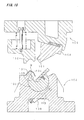
- a negative angle shaping mold is structured by a lower mold 102 which mounts a metal thin plate work W on a supporting portion 101, and an upper mold 103 which descends in a linear direction with respect to the lower mold 102 and comes into contact with the work W so as to shape the work W.
- the negative angle shaping mold is constituted by a rotary cam 106 which is open to an outer peripheral surface, has a groove 104 formed in a axial direction, forms an intrusion shaping portion 105 intruded from a locus of the upper mold 103 in an edge portion of the groove 104 close to the supporting portion 101, and is rotatably provided in the lower mold 102, a slide cam 108 which has an intrusion shaping portion 107, and is slidably provided in the upper mold 103 so as to oppose to the rotary cam 106, and an air cylinder 109 for an automatic resetting device which rotates and moves backward the rotary cam 106 to a state capable of taking out the work W from the lower mold 102 after shaping, and is provided in the lower mold 102.
- the work W mounted on the supporting portion 101 of the lower mold 102 is shaped by the intrusion shaping portion 105 of the rotary cam 106 and the intrusion shaping portion 107 of the slide cam 108 by sliding the slide cam 108, and the shaped work W can be taken out from the lower mold 102 by rotating and moving backward the rotary cam 106 by means of the air cylinder 109 after shaping.
- the upper mold 103 is positioned at a top dead center, and at this time, the work W is mounted on the supporting portion 101 of the lower mold 102. At this time, the rotary cam 106 is in a backward moving attitude by the air cylinder 109.
- the rotary cam 106 is in a shaping attitude by the air cylinder 109.
- the upper mold 103 starts descending, and the pad 110 presses the work W mounted on the supporting portion 101 of the lower mold 102.
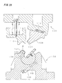
- the upper mold 103 is descended, and as shown in Fig. 17, a lower surface of the slide cam 108 is brought into contact with a rotary plate 111 without the slide cam 108 being interfered with the intrusion shaping portion 105 of the rotary cam 106.
- the slide cam 108 which is energized in an outer direction of the mold moves to a left side in a lateral direction due to an operation of the cam against an energizing force of a coil spring 112, and becomes in a state shown in Fig. 18, whereby an intrusion shaping of the work W is executed by the intrusion shaping portion 105 of the rotary cam 106 and the intrusion shaping portion 107 of the slide cam 108.
- the upper mold 103 After the intrusion shaping, the upper mold 103 starts ascending as shown in Fig. 19.
- the slide cam 108 is energized in the outer direction of the mold by the coil spring 112, is moved to a right side in Fig. 20 and is ascended without being interfered with the intrusion shaped work W.
- the slide cam 108 is ascended, and the rotary cam 106 is rotated to a right side in Fig. 16 by the air cylinder 108. Accordingly, at a time of taking out the intrusion shaped work W from the lower mold 102, the work W can be taken out without being interfered with the intrusion shaped portion 105 of the rotary cam 106.
- the rotary cam 106 takes the shaping attitude in accordance with a compressing operation of a piston rod 113 in the air cylinder 109, and takes the backward moving attitude in accordance with an expanding operation of the piston rod 113 in the air cylinder 109.
- the adjacent rotary cams are arranged in the other oblique shapes than the linear shape, the adjacent rotary cams are interfered with each other at a time when the rotary cams are rotated. In order to avoid this interference, it is necessary to execute the canceling process of canceling the interfered portion at a high accuracy, and a strength in the cancelled portion is lowered
- the present invention is made by taking the matters mentioned above into consideration, and an object of the present invention is to avoid an interference of rotary cams in a negative angle shaping mold. Further aspects are to avoid a canceling process in the rotary cam end portions, thereby reducing costs due to the high accuracy of the canceling process during manufacturing of the rotary cams and avoiding a reduction of the strength of the end portions.
- a negative angle shaping mold comprising a lower mold with a supporting portion on which a metal thin plate work can be mounted; an upper mold which is adapted to descend in a linear direction with respect to said lower mold and to come into contact with the work; a rotary cam comprising a plurality of rotary cam sections rotatably provided in the lower mold and being provided with an intrusion shaping portion intruded from a locus of the upper mold in an edge portion close to the supporting portion; a slide cam slidably provided so as to oppose to said rotary cam and having an intrusion shaping portion for shaping the work in cooperation with the intrusion shaping portion of the rotary cam; an automatic resetting device provided in the lower mold for rotating and moving backward the rotary cam to a backward moved state where the work can be taken out from the lower mold after shaping; and a rotary cam moving means for moving at least one of said rotary cam sections apart from an adjacent one of said rotary cam sections when the rotary cam is rotated to a backward moved
- a rotary cam moving apparatus of a negative angle shaping mold wherein a moving rail and a roller for guiding the moving rail are provided as moving means for moving the rotary cam from another rotary cam.
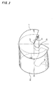
- Figs. 1 to 3 show a shaping attitude of rotary cams 1 and 2.
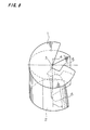
- Figs. 6 to 8 show a state in which the rotary cam 1 is stopped and the rotary cam 2 is moved backward and rotated at 30° , whereby end portions are interfered with each other.
- Figs. 9 to 11 show a state in which the rotary cam 2 is moved so as to be apart from the rotary cam 1 (about 10 mm) for the purpose of avoiding the interference between the end portions shown in Figs. 6 to 8.
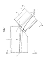
- Figs. 12 to 14 show a state in which the rotary cam 1 is further moved backward and rotated at 20° after the rotary cam 2 is moved backward and rotated at 30° .
- Figs. 1 to 3 shows the shaping attitude of the rotary cams 1 and 2.
- Fig. 2 is a view as seen along a line II-II in Fig. 1 and Fig. 3 is a view as seen along a line III-III in Fig. 1.
- a moving apparatus which moves the rotary cam 2 in a direction of moving apart from the rotary cam 1 at a time of moving backward and rotating the rotary cam 2.
- Reference numerals 3-3 and 4-4 respectively denote axes of rotation of the rotary cams 1 and 2
- reference numerals 5 and 6 denote corner ridge lines of the rotary cams 1 and 2 which form base ends of intrusion portions for a work.
- the corner ridge line 5 and the corner ridge line 6 are smoothly connected in the shaping attitude, and the intrusion portions are respectively formed from the corner ridge lines 5 and 6.
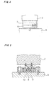
- a moving rail 8 is firmly fixed to the rotary cam 2 via a bracket 7, as shown in Figs. 1, 4 and 5.
- the moving rail 8 extends in a direction orthogonal to the rotational axis 4 of the rotary cam 2, and is shifted in an axial direction as illustrated between a start of the backward movement and rotation and an end of the backward movement and rotation.
- Rollers 10 which are rotatably provided in a lower mold 9 are brought into contact with both sides of the moving rail 8, whereby the moving rail 8 is guided.
- the moving rail 8 is constituted by a start straight portion 81, an end straight portion 82 and an intermediate oblique portion 83, and when the start straight portion 81 and the end straight portion 82 are positioned between the rollers 10, the rotary cam 2 is not moved in the axial direction.
- a connection portion between a front end of a piston rod in the air cylinder and the rotary cam 2 is structured such as to allow the rotary cam 2 to move in the axial direction.
- Figs. 6 to 8 show a state in which the rotary cam 1 is stopped and the rotary cam 2 is moved backward and rotated at 30° .
- Figs. 9 to 11 show a state in which the rotary cam 1 is stopped, the rotary cam 2 is backward moved and rotated at 30° , and at the same time the rotary cam 2 is moved apart from the rotary cam 1 at 10 mm.
- the end portion of the rotary cam 2 is going not to be interfered with the end portion of the rotary cam 1.
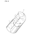
- Figs. 12 to 14 show a state in which the rotary cam 1 is backward moved and rotated at 20° , and the rotary cam 2 is backward moved and rotated at 30° and moved at 10 mm.
- an end surface angle ⁇ 2 of the rotary cam 1 is an obtuse angle, and the end surfaces in both elements are not interfered with each other.
- the moving rail and the roller for guiding the moving rail are provided, however, the present invention is not limited to this structure, and can employ a screw type movement, an air cylinder, a hydraulic pressure, a lever and the like.
- the rotary cam 2 is moved so that a gap is formed between the rotary cam 2 and the rotary cam 1, however, the rotary cam 1 may be moved together with the rotary cam 2 in a direction of moving apart from each other.
- the rotary cam 1 may be moved at a time when the rotary cam 2 starts a little rotating.
- the rotary cam 1 may be set to start moving after the rotary cam 2 finishes rotation.
- the rotary cam moving apparatus of the negative angle shaping mold comprising: a lower mold which mounts a metal thin plate work on a supporting portion; an upper mold which descends in a linear direction with respect to the lower mold and comes into contact with the work to shape the work; a rotary cam which forms an intrusion shaping portion intruded from a locus of the upper mold in an edge portion close to the supporting portion, and is rotatably provided in the lower mold; a slide cam which has an intrusion shaping portion, and is slidably provided so as to oppose to the rotary cam; and an automatic resetting device which rotates and moves backward the rotary cam to a backward moved state capable of taking out the work from the lower mold after shaping, and is provided in the lower mold, in which the work mounted on the supporting portion of the lower mold is shaped by the intrusion shaping portion of the rotary cam and the intrusion shaping portion of the slide cam by sliding the slide cam, and the shaped work is taken out from the
- the moving rail and the roller for guiding the moving rail are provided as moving means for being apart from another rotary cam.
Landscapes
- Engineering & Computer Science (AREA)
- Mechanical Engineering (AREA)
- Bending Of Plates, Rods, And Pipes (AREA)
- Mounting, Exchange, And Manufacturing Of Dies (AREA)
- Extrusion Moulding Of Plastics Or The Like (AREA)
Applications Claiming Priority (2)
| Application Number | Priority Date | Filing Date | Title |
|---|---|---|---|
| JP2002204227A JP2004042109A (ja) | 2002-07-12 | 2002-07-12 | 負角成形型の回転カム移動装置 |
| JP2002204227 | 2002-07-12 |
Publications (1)
| Publication Number | Publication Date |
|---|---|
| EP1380360A1 true EP1380360A1 (fr) | 2004-01-14 |
Family
ID=29728534
Family Applications (1)
| Application Number | Title | Priority Date | Filing Date |
|---|---|---|---|
| EP02017699A Withdrawn EP1380360A1 (fr) | 2002-07-12 | 2002-08-07 | Dispositif de déplacement d'une came rotative pour pliage angulaire négatif |
Country Status (7)
| Country | Link |
|---|---|
| US (1) | US20040007043A1 (fr) |
| EP (1) | EP1380360A1 (fr) |
| JP (1) | JP2004042109A (fr) |
| KR (1) | KR20040007188A (fr) |
| CN (1) | CN1467044A (fr) |
| CA (1) | CA2403565A1 (fr) |
| TW (1) | TW583039B (fr) |
Cited By (2)
| Publication number | Priority date | Publication date | Assignee | Title |
|---|---|---|---|---|
| DE102006051595A1 (de) * | 2006-11-02 | 2008-05-08 | Wilhelm Karmann Gmbh | Umformwerkzeug zur Umformung eines Werkstücks |
| CN105290181A (zh) * | 2015-12-04 | 2016-02-03 | 天津福臻工业装备有限公司 | 电伺服驱动侧围包边机 |
Families Citing this family (8)
| Publication number | Priority date | Publication date | Assignee | Title |
|---|---|---|---|---|
| US8436081B2 (en) * | 2010-08-31 | 2013-05-07 | U.S. Coatings IP Co. LLC. | High film build coating composition containing low molecular weight polytrimethylene ether glycol |
| JP5210365B2 (ja) * | 2010-09-17 | 2013-06-12 | 株式会社ユアビジネス | プレス成形用金型 |
| JP5690950B2 (ja) | 2010-12-02 | 2015-03-25 | ノルグレン オートメーション ソーリューションズ エルエルシーNorgren Automation Solutions,Llc. | 円形状カム装置を有する成形型 |
| TWI573641B (zh) * | 2014-04-15 | 2017-03-11 | Nat Kaohsiung First Univ Of Science And Tech | Camshaft forging cam angle twisting forming module |
| CN104972003B (zh) * | 2015-07-23 | 2017-05-24 | 高密市豪沃机械科技有限公司 | 通过液压系统驱动滑块实现侧整的汽车外覆盖件冲压模具 |
| JP6517622B2 (ja) * | 2015-07-31 | 2019-05-22 | ダイハツ工業株式会社 | ルーフサイドレール |
| CN106270071A (zh) * | 2016-10-13 | 2017-01-04 | 安徽江淮汽车股份有限公司 | 旋转侧翻边机构 |
| CN109794546A (zh) * | 2019-01-04 | 2019-05-24 | 安徽汇精模具研发科技有限公司 | 冲压件挤压成型装置 |
Citations (5)
| Publication number | Priority date | Publication date | Assignee | Title |
|---|---|---|---|---|
| JPH07185664A (ja) * | 1993-12-27 | 1995-07-25 | Toyota Motor Corp | プレス装置 |
| EP0699489A1 (fr) * | 1993-06-25 | 1996-03-06 | UMIX Co., Ltd. | Procédé pour former de la tÔle mince et matrice de formage |
| JPH1052719A (ja) * | 1996-08-06 | 1998-02-24 | Toyota Motor Corp | プレス装置の干渉防止装置 |
| JPH10166061A (ja) * | 1996-12-06 | 1998-06-23 | Toyota Auto Body Co Ltd | プレス型 |
| EP0857525A1 (fr) * | 1997-02-05 | 1998-08-12 | Umix Co., Ltd. | Matrice pour le formage de tÔle |
Family Cites Families (5)
| Publication number | Priority date | Publication date | Assignee | Title |
|---|---|---|---|---|
| DE3237928A1 (de) * | 1982-10-13 | 1984-04-19 | Karl Meinig KG, 7201 Rietheim-Weilheim | Vorrichtung zum anformen von flanschen an luftkanalwandungen |
| JP2002263754A (ja) * | 2001-03-05 | 2002-09-17 | Umix Co Ltd | 負角成形型の回転カム駆動装置 |
| JP3505157B2 (ja) * | 2001-03-05 | 2004-03-08 | ユミックス株式会社 | 負角成形型 |
| JP3492640B2 (ja) * | 2001-03-05 | 2004-02-03 | ユミックス株式会社 | 負角成形型 |
| JP3492642B2 (ja) * | 2001-03-21 | 2004-02-03 | ユミックス株式会社 | 負角成形型の回転カム移動装置 |
-
2002
- 2002-07-12 JP JP2002204227A patent/JP2004042109A/ja not_active Ceased
- 2002-08-07 EP EP02017699A patent/EP1380360A1/fr not_active Withdrawn
- 2002-08-09 KR KR1020020047018A patent/KR20040007188A/ko not_active Withdrawn
- 2002-09-04 TW TW091120113A patent/TW583039B/zh not_active IP Right Cessation
- 2002-09-11 CN CNA021315582A patent/CN1467044A/zh active Pending
- 2002-09-16 CA CA002403565A patent/CA2403565A1/fr not_active Abandoned
- 2002-11-22 US US10/301,688 patent/US20040007043A1/en not_active Abandoned
Patent Citations (5)
| Publication number | Priority date | Publication date | Assignee | Title |
|---|---|---|---|---|
| EP0699489A1 (fr) * | 1993-06-25 | 1996-03-06 | UMIX Co., Ltd. | Procédé pour former de la tÔle mince et matrice de formage |
| JPH07185664A (ja) * | 1993-12-27 | 1995-07-25 | Toyota Motor Corp | プレス装置 |
| JPH1052719A (ja) * | 1996-08-06 | 1998-02-24 | Toyota Motor Corp | プレス装置の干渉防止装置 |
| JPH10166061A (ja) * | 1996-12-06 | 1998-06-23 | Toyota Auto Body Co Ltd | プレス型 |
| EP0857525A1 (fr) * | 1997-02-05 | 1998-08-12 | Umix Co., Ltd. | Matrice pour le formage de tÔle |
Non-Patent Citations (3)
| Title |
|---|
| PATENT ABSTRACTS OF JAPAN vol. 1995, no. 10 30 November 1995 (1995-11-30) * |
| PATENT ABSTRACTS OF JAPAN vol. 1998, no. 06 30 April 1998 (1998-04-30) * |
| PATENT ABSTRACTS OF JAPAN vol. 1998, no. 11 30 September 1998 (1998-09-30) * |
Cited By (3)
| Publication number | Priority date | Publication date | Assignee | Title |
|---|---|---|---|---|
| DE102006051595A1 (de) * | 2006-11-02 | 2008-05-08 | Wilhelm Karmann Gmbh | Umformwerkzeug zur Umformung eines Werkstücks |
| DE102006051595B4 (de) * | 2006-11-02 | 2009-12-17 | Wilhelm Karmann Gmbh | Umformwerkzeug zur Umformung eines Werkstücks |
| CN105290181A (zh) * | 2015-12-04 | 2016-02-03 | 天津福臻工业装备有限公司 | 电伺服驱动侧围包边机 |
Also Published As
| Publication number | Publication date |
|---|---|
| JP2004042109A (ja) | 2004-02-12 |
| CN1467044A (zh) | 2004-01-14 |
| KR20040007188A (ko) | 2004-01-24 |
| US20040007043A1 (en) | 2004-01-15 |
| TW583039B (en) | 2004-04-11 |
| CA2403565A1 (fr) | 2004-01-12 |
Similar Documents
| Publication | Publication Date | Title |
|---|---|---|
| EP0857525B1 (fr) | Matrice pour le formage de tôle | |
| EP0699489B1 (fr) | Matrice de formage former de la tÔle mince | |
| EP1369187A2 (fr) | Appareil d'entraínement rotatif pour un corps rotatif | |
| EP0858847B1 (fr) | Matrice de formage de tôle mince | |
| US5740691A (en) | Hemming machine | |
| EP1380360A1 (fr) | Dispositif de déplacement d'une came rotative pour pliage angulaire négatif | |
| EP1238721A2 (fr) | Outillage de formage pour pliage angulaire négatif | |
| KR20020075174A (ko) | 부각 성형 다이의 로터리 캠 이동 장치 | |
| JP2579530B2 (ja) | ヘミング成形方法 | |
| EP1181996B1 (fr) | Dispositif et méthode de rabattage | |
| KR20120051793A (ko) | 플랜지 음각 가공을 위한 프레스의 승하강 장치 | |
| JP2866629B2 (ja) | 薄板の成形型 | |
| CN1110382C (zh) | 薄板成形模 | |
| JPS60166122A (ja) | 薄板の成形方法とその成形型 | |
| CA2196929C (fr) | Matrices pour toles minces | |
| JPH08256B2 (ja) | 薄板の成形型 | |
| JP3492486B2 (ja) | 薄板の成形型 | |
| JPH089067B2 (ja) | 自動車用ドアサッシュのヘミング加工装置 | |
| JPS5919033A (ja) | 折曲げ用プレス型 | |
| JPS637384Y2 (fr) | ||
| KR100242672B1 (ko) | 박판의 성형방법과 그것의 성형형 | |
| JP2866630B2 (ja) | 薄板の成形型 | |
| JP2520585Y2 (ja) | プレス型 | |
| JP6502432B2 (ja) | ダイならびにローラーヘミング加工システムおよび金属ワークにローラーヘミング加工を施す方法 | |
| CN1212188A (zh) | 模压装置 |
Legal Events
| Date | Code | Title | Description |
|---|---|---|---|
| PUAI | Public reference made under article 153(3) epc to a published international application that has entered the european phase |
Free format text: ORIGINAL CODE: 0009012 |
|
| AK | Designated contracting states |
Kind code of ref document: A1 Designated state(s): AT BE BG CH CY CZ DE DK EE ES FI FR GB GR IE IT LI LU MC NL PT SE SK TR |
|
| AX | Request for extension of the european patent |
Extension state: AL LT LV MK RO SI |
|
| 17P | Request for examination filed |
Effective date: 20040209 |
|
| 17Q | First examination report despatched |
Effective date: 20040716 |
|
| AKX | Designation fees paid |
Designated state(s): DE ES FR GB IT SE |
|
| GRAP | Despatch of communication of intention to grant a patent |
Free format text: ORIGINAL CODE: EPIDOSNIGR1 |
|
| STAA | Information on the status of an ep patent application or granted ep patent |
Free format text: STATUS: THE APPLICATION IS DEEMED TO BE WITHDRAWN |
|
| 18D | Application deemed to be withdrawn |
Effective date: 20050708 |