EP0858847B1 - Matrice de formage de tôle mince - Google Patents
Matrice de formage de tôle mince Download PDFInfo
- Publication number
- EP0858847B1 EP0858847B1 EP97101919A EP97101919A EP0858847B1 EP 0858847 B1 EP0858847 B1 EP 0858847B1 EP 97101919 A EP97101919 A EP 97101919A EP 97101919 A EP97101919 A EP 97101919A EP 0858847 B1 EP0858847 B1 EP 0858847B1
- Authority
- EP
- European Patent Office
- Prior art keywords
- die
- cam
- rotating cam
- forming
- negative angle
- Prior art date
- Legal status (The legal status is an assumption and is not a legal conclusion. Google has not performed a legal analysis and makes no representation as to the accuracy of the status listed.)
- Expired - Lifetime
Links
Images



Classifications
-
- B—PERFORMING OPERATIONS; TRANSPORTING
- B21—MECHANICAL METAL-WORKING WITHOUT ESSENTIALLY REMOVING MATERIAL; PUNCHING METAL
- B21D—WORKING OR PROCESSING OF SHEET METAL OR METAL TUBES, RODS OR PROFILES WITHOUT ESSENTIALLY REMOVING MATERIAL; PUNCHING METAL
- B21D22/00—Shaping without cutting, by stamping, spinning, or deep-drawing
- B21D22/02—Stamping using rigid devices or tools
- B21D22/08—Stamping using rigid devices or tools with die parts on rotating carriers
-
- B—PERFORMING OPERATIONS; TRANSPORTING
- B21—MECHANICAL METAL-WORKING WITHOUT ESSENTIALLY REMOVING MATERIAL; PUNCHING METAL
- B21D—WORKING OR PROCESSING OF SHEET METAL OR METAL TUBES, RODS OR PROFILES WITHOUT ESSENTIALLY REMOVING MATERIAL; PUNCHING METAL
- B21D19/00—Flanging or other edge treatment, e.g. of tubes
- B21D19/08—Flanging or other edge treatment, e.g. of tubes by single or successive action of pressing tools, e.g. vice jaws
- B21D19/082—Flanging or other edge treatment, e.g. of tubes by single or successive action of pressing tools, e.g. vice jaws for making negative angles
- B21D19/086—Flanging or other edge treatment, e.g. of tubes by single or successive action of pressing tools, e.g. vice jaws for making negative angles with rotary cams
Definitions
- the invention relates to thin sheet forming die as defined in the preamble portion of claim 1.
- the negative angle of thin sheets such as sheet metal or plastics is generally formed by the use of a slide cam.
- the negative angle forming referred to here means forming with a forming portion which comes inwards towards the lower die from the working locus of the upper die when the work loaded on the lower die is formed by descending the upper die in the vertical direction for abutting.
- the work is loaded on the lower die and the upper die descends downwards in the vertical direction to drive the driven cam of the lower die by the driving cam of the upper die, and the work is processed from the lateral direction, and when processing completes and the upper die ascends, the driven cam is retracted by springs.
- the forming portion of the driven cam which slides and forms the work from the outward lateral direction of. the work is formed in the integrated profile identical to that of the forming portion of the work, but the forming portion of the lower die with the work loaded must be designed to divide and retract the portion forming a negative angle of the lower die, or the rear portion forming the negative angle is deleted and the work is moved forward to enable the removal of the work.
- the driven cam In negative angle forming using the slide cam, the driven cam is slid in a considerably long straight distance for forming, it is not always easy to repeatedly slide the driven cam exactly to a specified position and it is difficult to produce products with stable quality.
- any distortion or bend is generated in products, it is difficult to combine such products with other parts and it is impossible to provide a high-quality automobile sheet metal structure and to maintain a specified product accuracy of thin-plate formed products.
- FIG. 4 shows right and left schematic perspective views of a complete front pillar outer, an automobile sheet metal part formed by the forming dies.
- the bottom shows the front pillar outer for the right side and the top for the left side.
- This front pillar outer constitutes part of the front door frame, also part of the front wind shield frame, and in addition part of the frame supporting the roof panel, and comprises the joint part with other many parts, and is a product for which severe product accuracy is required, and if the required accuracy is not satisfied, it is unable to provide a sheet metal car body with good quality.
- the front pillar outer composes the outer plate portion of the automobile, it has three-dimensional curved surfaces and profiles.
- this press-working process includes drawing which takes place first, then, peripheral trimming to the condition shown in Fig. 5, and this forming process as the succeeding third process.
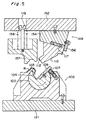
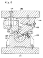
- a cylindrical rotating can 102 formed with an axial groove 101 is rotatably mounted to the lower die proper 103.
- the lower die proper 103 is securely fixed to the lower substrate 121 with a bolt 122.
- the top surface of the lower die proper 103 is formed in a shape that can receive the work W, and a negative angle forming portion 104 is formed at the edge portion of the groove 101 of the rotating cam 102 nearest to the top surface of the lower die 103.
- An automatic return device 105 which rotates and retracts the rotating cam 102 is embedded in the lower die proper 103 so that the work W can be removed from the lower die proper 103 after forming.
- the automatic return device 105 brings a push pin 107 energized by coil spring 106 in contact with the bottom surface of the tip end of the rolling plate 108 securely fixed to the surface opposite to the negative angle forming portion 104 of the groove 101 of the rotating cam 102 with a bolt 151.
- pneumatic devices, hydraulic devices, link mechanisms, cams, or other similar mechanisms may be used, and may be mounted not only to the lower die 100 but also between the upper die 109 and the lower die 100.
- a slide cam 110 is mounted to the position opposite to the said rotating cam 102.
- This slide cam 110 has the negative angle forming portion 112 formed at the bottom end, the slide cam 110 is guided by the guide (not illustrated), and is energized in the outward direction of the die by a coil spring 117 compressedly mounted between the slide cam 110 top surface and the inclined guide 154 bottom surface securely fixed to the top substrate 152 with a bolt 153.
- the slide cam 110 is stopped by a stopping plate 156 securely affixed to the inclined guide 154 with a bolt 155.
- a pad 157 is energized downwards by a coil spring 158, is hung from the top substrate 152 with a hang bolt 119, and strongly presses the work W against the lower die proper 103 to prevent the work W from moving before the negative angle is formed on the work W.
- the upper die 109 is located at the top dead center, and then, the work W is loaded on the lower die proper 103 of the lower die 100. In this event, the rotating cam 102 is rolled and retracted by the automatic return device 105.
- the upper die 109 begins descending and as shown in Fig. 6, first of all, the bottom surface of the slide cam 110 comes in contact with the rolling plate 108 to rotate the rotating cam 102 clockwise in Fig. 6 without causing the slide cam 110 to interfere with the negative angle forming portion 104 of the rotating cam 102.
- the slide cam 110 energized in the outward direction of the die resists against the energizing force of the coil spring 117, moves to the left in the lateral direction by the operation of the can, enters the state shown in Fig. 7, and the negative-angle forming portion 104 of the rolled rotating cam 102 cooperates with the negative-angle forming portion 112 of the slide cam 110 to negative-angle form the work W.
- the upper die 109 begins rising.
- the slide cam 110 is energized in the outward direction of the die by the coil spring 117, moves to the right in Fig. 8, and ascends without interfering with the work W with the negative angle formed.
- the rotating cam 102 rotates to the right in Fig. 8 by the automatic return device because the slide cam 110 being restrained ascends, enabling the work W to be removed without interfering with the negative angle forming portion 104 of the rotating cam 102 when the negative-angle formed work W is removed from the lower die 103.
- the formed thin sheet products had the negative angle formed using the rotating cam as described above, but because the rotating cam rotates around the rotation axis to process the work, if the work is nearly linear and is not greatly bent, the negative angle forming portion can enter one of the cylindrical rotating cams in the same diameter and is able to be processed, but if the work is greatly bent, the negative angle forming portion is unable to completely enter one of the cylindrical rotating cams in the sane diameter and is unable to be processed.
- automobile sheet metal parts including door panels have many bent portions, and in recent years, there are many negative angle forming portions from the viewpoint of designs in addition to conventional bent portions, and it is demanded to form these negative angle forming portions in one process without undergoing many processes and to improve production efficiency.
- a prior art thin sheet forming die with the features of the preamble portion of claim 1 is described in US-A-5 347 838.
- This thin sheet forming die has basically the features of the die shown in Figures 5 to 8 and in addition has a plurality of dedicated rotary cams constituting plural forming portions arranged substantially straight within the range capable of processing with one rotary cam.
- the invention provides a thin sheet forming die as defined in claim 1.
- a preferred embodiment of this thin sheet forming die is defined in the subclaim.
- the size of the rotating cam diameter is practically unable to be excessively increased from the viewpoint of fabricating dies, and is, for example, about 320 mm, and for the greatly bent work, the bent portions are processed by one rotating cam equipped with a plurality of cylindrical rotating cam portions in different diameters.
- the diameters are varied at a required position of the rotation axis in accord with the degree of the bend of the work. Special consideration shall be given to the size of diameter of the rotating cam so that the negative angle forming portion of the rotating cam does not become excessively acute. Because the negative angle forming portion becomes excessively acute, the strength lacks, and it is preferable to take care to prevent it from becoming 30° or less.
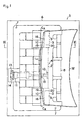
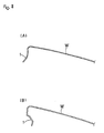
- the work W formed by the forming dies according to this invention is an automobile trunk lid outer as shown in Fig. 1, and the recessed circular arc curved portion of the front edge portion of the trunk lid outer as viewed from the plane is negative-angle formed, and as shown in Fig. 2, it is negative-angle formed to have a cross-section shown below from that shown above.
- Fig. 1 shows a plan view of the thin sheet forming dies
- Fig. 2 the condition of a flange 1 before and after the work W is processed
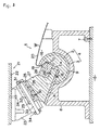
- Fig. 3 a longitudinal cross-sectional view taken on the line III-III of Fig. 1.
- the processed portion of the work W of the thin sheet forming dies is the rear edge portion of the trunk lid outer and as clear from Fig. 1, it is a protruded form as seen from the plane, and both end portions are considerably displaced forwards. If this is processed with one piece of rotating cam, an extremely large rotating cam is required. Excessively increasing the size is practically impossible in fabricating dies, and is about 320 mm in diameter at maximum.
- the flange angle differs at the center portion and both end portions, and there is a case in which the negative-angle forming portion of the rotating cam becomes too acute to maintain the strength.
- the rotating cam is formed into a small-diameter center rotating cam portion at the center portion and large-diameter rotating cam portions at both ends.
- a rotating cam comprising large-diameter edge portion rotating can portions 3 are arranged on both ends of the small-diameter center rotating cam portion 2 of the rotating axis CA in Fig. 1, a rotating cam comprising large-diameter edge portion rotating can portions 3 are arranged.
- the large-diameter edge portion rotating cam portions 3 are concentric to the small-diameter center rotating cam portion 2, and has a larger diameter than the small-diameter center rotating cam portion 2.
- the diameter of the large-diameter edge portion rotating cam portions is 290 mm, and that of the small-diameter center portion rotating cam portion is 250 mm.
- the lower die 5 has a support block 8 fixed to the lower die base 6 with a bolt 7, and rotatably supports the cylindrical large-diameter edge portion rotating cam 3 with a axially formed groove 10 in a horizontal slot groove 9 at the top center of the support block 8.
- an air cylinder 11 is equipped as an automatic return device of the rotating cam 4 in Fig. 1.
- the automatic return device is not limited to an air cylinder but a spring, hydraulic equipment, link mechanism, cam, or any mechanisms similar to these may be used, and can be mounted not only to the lower die but also to the upper die.
- a connecting member 12 is fixed to the bottom surface of the small-diameter center rotating cam 2, and to the tip end of a piston rod 15 of the air cylinder whose base end is pivotally mounted via the bracket 14 fixed to the support block 8 with a bolt 13, the said connecting member 12 is pivotally mounted, so that the piston rod 14 is contracted to return the small-diameter center rotating cam 2.
- a window slot is provided for allowing the connecting member 12 to rotate.
- a negative angle forming portion 16 is formed, and a rolling plate 17 is fixed to the side opposite to the negative angle forming portion 16 of the groove 10 with a bolt 18.
- the negative angle forming portion 16 of the large diameter edge portion rotating cam portion 3 is formed into a work support portion 19 in the profile same as the bottom surface of the work W so that the work W is supported, and a work loading portion 20 in the profile same as the bottom surface of the work W is formed slightly outwards in the upper portion linked to the work supporting portion 19 of the edge portion rotating cam portion 3 of the support block 8.
- the upper die 21 has a support block 23 fixed to the lower surface of the upper die base 22 with a bolt 24, and a wear plate 25 fixed to the lower inclined surface of the support block 23 with a bolt 26, and the slide cam 27 is held by a guide plate (not illustrated) and slid on the lower surface of the wear plate 25.
- the negative angle forming portion 28 is fixed with a bolt, at the opposite position to the groove 10 of the edge portion rotating cam 3 of the slide cam 27.
- a support plate 29 is fixed with a bolt 30, and between this support plate 29 and the support plate 31 fixed to the support block 23, a coil spring 32 is compressedly mounted to energize the slide cam 27 to the outward direction of the die.
- the said coil spring 32 is mounted in the externally fitted form to the positioning pin 33 screwed into the support plate 31, and the tip end of the said positioning pin 33 allows a stopping plate 34 fixed to the side surface opposite to the support plate 31 to pass through.
- the positioning member of the work W is mounted to the lower die 5, and to the upper die 21, as described in the conventional example, a pad for pressurizing the work W is mounted to the lower die 5, but as these would make the illustration complicated and essential points of this invention difficult to understand, the positioning member and the pad are omitted.
- the small-diameter center rotating cam portion 2 is shown with an alternate long and two short dashes line, and others are nearly identical to the large-diameter rotating cam portion.
- the condition shown in Fig. 3 is the bottom dead center condition and corresponds to Fig. 7 of the conventional example.
- the upper die 21 is located at the top dead center, when the work W is loaded to the work support portions 20 of the lower die 5. In this event, the center rotating cam 2 is rolled to retract by the air cylinder 11.
- the inclined surface 41 of the slide cam 27 comes in contact with the rolling plate 17 without allowing the slide cam 27 to interfere with the negative angle forming portion 16 of the small-diameter center rotating cam 2 and large-diameter edge portion rotating cam portion 3, causing the small-diameter center rotating cam 2 and large-diameter edge portion rotating cam portion 3 to rotate counterclockwise (the rolling direction is reversal in the conventional example and this embodiment).
- the slide cam 27 energized in the outward direction of the dies resists against the energizing force of the coil spring 32 and moves to the right in the lateral direction by the action of the cam, and enters the condition shown in Fig. 7 of the conventional example, that is, the condition shown in Fig. 3, and the negative angle forming portion 16 of the small-diamether center rotating cam portion 2 and large-diameter edge portion rotating cam 3 cooperate with the negative angle forming portion 28 of the slide cam 27 to negative-angle form the work W.
- the upper die 21 After negative-angle forming, the upper die 21 begins to ascend.
- the slide cam 27 is energized in the outward direction of the dies by the coil spring 32, moves to the left as shown in Fig. 8 of the conventional example, and ascends without interfering with the negative-angle formed work W.
- This invention is a forming die with a forming portion to achieve a negative angle when the second die is moved in the straight line to abut the first die for forming, and in the thin sheet forming dies in which a cylindrical rotating cam with a groove formed in the axial direction is rotatably mounted to the first die, a negative angle forming portion is formed in the groove edge portion of the rotating cam, a slide cam with the negative angle forming portion is mounted to the second die in such a manner to be opposite to the said rotating cam, an automatic return device for rotating and retracting the rotating cam to enable the removal of the work from the first die after forming is mounted to the first die, because it is a thin sheet forming die designed to process an excessively bent negative angle forming portion with one rotating cam equipped with a plurality of integral cylindrical rotating cam portions with different diameters, it becomes possible to form an excessively bent negative angle forming portion with one forming die, to reduce the number of processes, and to improve the processing accuracy.
- the thin sheet forming die according to this invention is suited for negative-angle forming the protruded circular are curved portion as seen from the plane. This is because the flange to be formed becomes a shrinkage flange as it is protruded and tends to generate wrinkles at the time of forming, requiring bottom pushing processing. In this invention, because the rotating cams are formed integrally, bottom pushing forming is possible in high accuracy.
Landscapes
- Engineering & Computer Science (AREA)
- Mechanical Engineering (AREA)
- Bending Of Plates, Rods, And Pipes (AREA)
- Mounting, Exchange, And Manufacturing Of Dies (AREA)
- Folding Of Thin Sheet-Like Materials, Special Discharging Devices, And Others (AREA)
- Shaping Of Tube Ends By Bending Or Straightening (AREA)
Claims (2)
- Matrice de formage de tôle mince destinée former une pièce de tôle mince (W) comportant une partie incurvée lorsqu'elle est vue depuis un plan et un angle négatif dans sa section droite, comprenant :caractérisée en ce queune première matrice (21) pouvant être déplacée en direction d'une seconde matrice (5) pour être mise en butée contre la seconde matrice (5) ;une came cylindrique tournante (4) montée, pour pouvoir tourner, sur la seconde matrice (5), ladite came cylindrique tournante (4) présentant une gorge (10) formée dans sa direction axiale et une partie de formation d'angle négatif (16) formée sur une partir de bord de gorge de la came tournante (4) ;une came coulissante (27) ayant une partie de formation d'angle négatif (28) disposée sur la première matrice (21) de manière à être opposée à ladite came tournante (4) et à coopérer avec la partie de formation d'angle négatif (16) de la came tournante (4) lorsque la première matrice (21) se rapproche de la seconde matrice (5) pour former l'angle négatif sur la pièce (W) placée sur la seconde matrice (5) ; etun dispositif de renvoi automatique (11) monté sur la première ou la seconde matrice (21, 5) pour faire tourner la came tournante (4) jusqu'à une position dans laquelle la pièce (W) peut être retirée de la seconde matrice (5) après formage,la came tournante (4) comporte une pluralité de parties de cames cylindriques intégrées (2, 3), qui sont latéralement adjacentes les unes aux autres, ayant différents diamètres pour traiter la partie incurvée de la pièce (W) au moyen de l'angle négatif.
- Matrice de formage de tôle mince selon la revendication 1, caractérisée en ce que ladite came tournante (4) comprend une partie de came centrale de petit diamètre (2) et des parties de cames de bord de grand diamètre (3) concentriques à ladite partie de came centrale (2).
Priority Applications (4)
| Application Number | Priority Date | Filing Date | Title |
|---|---|---|---|
| US08/795,779 US5746082A (en) | 1997-02-05 | 1997-02-05 | Thin sheet forming die assembly including lower die cylindrical member having varied diameters |
| ES97101919T ES2166019T3 (es) | 1997-02-05 | 1997-02-06 | Matrices conformadoras de chapa delgada. |
| EP97101919A EP0858847B1 (fr) | 1997-02-05 | 1997-02-06 | Matrice de formage de tôle mince |
| DE69708834T DE69708834T2 (de) | 1997-02-05 | 1997-02-06 | Formgesenk von dünnen Blech |
Applications Claiming Priority (2)
| Application Number | Priority Date | Filing Date | Title |
|---|---|---|---|
| US08/795,779 US5746082A (en) | 1997-02-05 | 1997-02-05 | Thin sheet forming die assembly including lower die cylindrical member having varied diameters |
| EP97101919A EP0858847B1 (fr) | 1997-02-05 | 1997-02-06 | Matrice de formage de tôle mince |
Publications (2)
| Publication Number | Publication Date |
|---|---|
| EP0858847A1 EP0858847A1 (fr) | 1998-08-19 |
| EP0858847B1 true EP0858847B1 (fr) | 2001-12-05 |
Family
ID=26145211
Family Applications (1)
| Application Number | Title | Priority Date | Filing Date |
|---|---|---|---|
| EP97101919A Expired - Lifetime EP0858847B1 (fr) | 1997-02-05 | 1997-02-06 | Matrice de formage de tôle mince |
Country Status (4)
| Country | Link |
|---|---|
| US (1) | US5746082A (fr) |
| EP (1) | EP0858847B1 (fr) |
| DE (1) | DE69708834T2 (fr) |
| ES (1) | ES2166019T3 (fr) |
Cited By (1)
| Publication number | Priority date | Publication date | Assignee | Title |
|---|---|---|---|---|
| WO2014195591A1 (fr) | 2013-06-03 | 2014-12-11 | Peugeot Citroen Automobiles Sa | Outil d'emboutissage à coulisseau embarqué sur presseur rotatif |
Families Citing this family (24)
| Publication number | Priority date | Publication date | Assignee | Title |
|---|---|---|---|---|
| US6189360B1 (en) * | 1998-06-15 | 2001-02-20 | Sanyo Machine America Corp. | Metal forming machine |
| US6038908A (en) * | 1998-12-08 | 2000-03-21 | Yourbusiness Co., Ltd. | Bending die having rotary die |
| JP3051735B1 (ja) * | 1999-04-15 | 2000-06-12 | ユミックス株式会社 | 負角成形型とその加圧装置 |
| JP3644312B2 (ja) * | 1999-07-05 | 2005-04-27 | トヨタ自動車株式会社 | プレス成形型 |
| JP3370628B2 (ja) * | 1999-11-15 | 2003-01-27 | ユミックス株式会社 | 負角成形型 |
| JP2002263754A (ja) | 2001-03-05 | 2002-09-17 | Umix Co Ltd | 負角成形型の回転カム駆動装置 |
| JP3492640B2 (ja) * | 2001-03-05 | 2004-02-03 | ユミックス株式会社 | 負角成形型 |
| JP3492642B2 (ja) * | 2001-03-21 | 2004-02-03 | ユミックス株式会社 | 負角成形型の回転カム移動装置 |
| US7422562B2 (en) * | 2003-12-05 | 2008-09-09 | Edwards Lifesciences | Real-time measurement of ventricular stroke volume variations by continuous arterial pulse contour analysis |
| US6978651B2 (en) * | 2004-06-01 | 2005-12-27 | Anchor Lamina America, Inc. | Roller cam |
| US6990844B1 (en) | 2004-07-27 | 2006-01-31 | Anchor Lamina America, Inc. | Narrow aerial and die-mount cams |
| US7523634B2 (en) * | 2004-08-24 | 2009-04-28 | Helical Cam, Llc. | Forming die having filler cam assembly |
| US7431502B2 (en) * | 2004-09-15 | 2008-10-07 | Anchor Lamina America, Inc. | Universal cam slide |
| US8171821B2 (en) | 2006-09-28 | 2012-05-08 | Helical Cam, Llc | Corner cam assembly |
| FR2914571B1 (fr) * | 2007-04-04 | 2009-09-04 | Peugeot Citroen Automobiles Sa | Outil d'emboutissage pour la mise en forme des bords d'une piece de tolerie, notamment d'un capot de vehicule |
| WO2008144237A1 (fr) * | 2007-05-18 | 2008-11-27 | Danly Iem, Llc | Machine à cintrer par enroulement - compression avec une structure d'appui-guide hybride |
| US7735907B2 (en) * | 2007-12-27 | 2010-06-15 | Toyota Motor Engineering & Manufacturing North America, Inc. | Pillar for motor vehicle and tool for making the same |
| US8516874B2 (en) * | 2007-12-27 | 2013-08-27 | Toyota Motor Engineering & Manufacturing North America, Inc. | Pillar for motor vehicle and tool for making the same |
| JP5690950B2 (ja) | 2010-12-02 | 2015-03-25 | ノルグレン オートメーション ソーリューションズ エルエルシーNorgren Automation Solutions,Llc. | 円形状カム装置を有する成形型 |
| FR2985672A1 (fr) * | 2012-01-13 | 2013-07-19 | Peugeot Citroen Automobiles Sa | Outillage d'emboutissage de toles comportant des rebords |
| FR3009979B1 (fr) * | 2013-08-27 | 2015-08-21 | Peugeot Citroen Automobiles Sa | Emboutissage et poinconnage simultane d'une piece avec une portion en contre-depouille |
| EP3342496B1 (fr) * | 2016-11-02 | 2019-03-13 | Flight Corporation | Dispositif de pliage des tôles en forme d'échalon |
| US11213878B2 (en) | 2019-03-01 | 2022-01-04 | Hvac Inventors/Systemation, Inc. | Apparatus and method for forming duct flanges and duct work |
| CN110773623A (zh) * | 2019-12-17 | 2020-02-11 | 哈工大机器人(岳阳)军民融合研究院 | 电磁冲孔成形装置 |
Family Cites Families (12)
| Publication number | Priority date | Publication date | Assignee | Title |
|---|---|---|---|---|
| US4365500A (en) * | 1981-01-30 | 1982-12-28 | Chesley F. Carlson Company | Web bending fixture |
| US4535619A (en) * | 1982-10-13 | 1985-08-20 | Gargrave Robert J | Rotary bending, particularly for press brakes |
| DE3237928A1 (de) * | 1982-10-13 | 1984-04-19 | Karl Meinig KG, 7201 Rietheim-Weilheim | Vorrichtung zum anformen von flanschen an luftkanalwandungen |
| JPS59197318A (ja) * | 1983-04-21 | 1984-11-08 | Daihatsu Motor Co Ltd | プレス用金型 |
| JPS6160226A (ja) | 1984-08-31 | 1986-03-27 | Hitachi Ltd | パイプ拡管機 |
| JPS6341652A (ja) * | 1986-08-07 | 1988-02-22 | Nissan Motor Co Ltd | 排気還流装置の故障診断装置 |
| US4875356A (en) * | 1988-08-23 | 1989-10-24 | Deere & Company | Material fabricating mechanism |
| EP0427886A1 (fr) * | 1989-11-16 | 1991-05-22 | Uemura Metal Industries Co., Ltd. | Organe de formage pour pliage angulaire negatif |
| JP2927382B2 (ja) * | 1993-01-14 | 1999-07-28 | ダイハツ工業株式会社 | プレス装置のロータリーカム構造 |
| US5347838A (en) * | 1993-06-25 | 1994-09-20 | Umix Co., Ltd. | Forming die for thin plate |
| JPH081242A (ja) * | 1994-06-20 | 1996-01-09 | Toyota Motor Corp | プレス装置 |
| JPH08276218A (ja) * | 1995-04-04 | 1996-10-22 | Mazda Motor Corp | 板材の成形装置 |
-
1997
- 1997-02-05 US US08/795,779 patent/US5746082A/en not_active Expired - Lifetime
- 1997-02-06 ES ES97101919T patent/ES2166019T3/es not_active Expired - Lifetime
- 1997-02-06 DE DE69708834T patent/DE69708834T2/de not_active Expired - Lifetime
- 1997-02-06 EP EP97101919A patent/EP0858847B1/fr not_active Expired - Lifetime
Cited By (1)
| Publication number | Priority date | Publication date | Assignee | Title |
|---|---|---|---|---|
| WO2014195591A1 (fr) | 2013-06-03 | 2014-12-11 | Peugeot Citroen Automobiles Sa | Outil d'emboutissage à coulisseau embarqué sur presseur rotatif |
Also Published As
| Publication number | Publication date |
|---|---|
| ES2166019T3 (es) | 2002-04-01 |
| DE69708834D1 (de) | 2002-01-17 |
| EP0858847A1 (fr) | 1998-08-19 |
| US5746082A (en) | 1998-05-05 |
| DE69708834T2 (de) | 2002-08-08 |
Similar Documents
| Publication | Publication Date | Title |
|---|---|---|
| EP0858847B1 (fr) | Matrice de formage de tôle mince | |
| EP0857525B1 (fr) | Matrice pour le formage de tôle | |
| EP0699489B1 (fr) | Matrice de formage former de la tÔle mince | |
| EP1535674B1 (fr) | Outillage de formage d'une presse pour pliage angulaire négatif | |
| EP1477245B1 (fr) | Dispositif de formage successif | |
| US6523386B2 (en) | Negative-angle forming die | |
| US5253502A (en) | Apparatus and method for bending and forming sheet material | |
| WO1995021711A1 (fr) | Machine de rabattage perfectionnee | |
| EP0979692A2 (fr) | Unité de sertissage à rouleau multiaxiale | |
| CA2196929C (fr) | Matrices pour toles minces | |
| EP1380360A1 (fr) | Dispositif de déplacement d'une came rotative pour pliage angulaire négatif | |
| EP0427886A1 (fr) | Organe de formage pour pliage angulaire negatif | |
| CA2196928C (fr) | Matrices pour toles minces | |
| US8181498B2 (en) | Method and apparatus for shaping a rim of a three-dimensionally arched sheet metal | |
| JPH06344030A (ja) | 薄板の成形方法とその成形型 | |
| JP2866629B2 (ja) | 薄板の成形型 | |
| US20080083258A1 (en) | Tilting System for a Flanging Device | |
| JP2866630B2 (ja) | 薄板の成形型 | |
| KR100468532B1 (ko) | 박판의성형형 | |
| CN1194185A (zh) | 薄板成形模 | |
| CN1099923C (zh) | 薄板成形模 | |
| CN217044076U (zh) | 侧围外板整形机构 | |
| KR100468533B1 (ko) | 박판의성형형 | |
| JPS60166122A (ja) | 薄板の成形方法とその成形型 | |
| JPS61165233A (ja) | 車両用開閉体の製造方法 |
Legal Events
| Date | Code | Title | Description |
|---|---|---|---|
| PUAI | Public reference made under article 153(3) epc to a published international application that has entered the european phase |
Free format text: ORIGINAL CODE: 0009012 |
|
| AK | Designated contracting states |
Kind code of ref document: A1 Designated state(s): DE ES FR GB IT SE |
|
| 17P | Request for examination filed |
Effective date: 19990215 |
|
| AKX | Designation fees paid |
Free format text: DE ES FR GB IT SE |
|
| RBV | Designated contracting states (corrected) |
Designated state(s): DE ES FR GB IT SE |
|
| 17Q | First examination report despatched |
Effective date: 20000324 |
|
| GRAG | Despatch of communication of intention to grant |
Free format text: ORIGINAL CODE: EPIDOS AGRA |
|
| GRAG | Despatch of communication of intention to grant |
Free format text: ORIGINAL CODE: EPIDOS AGRA |
|
| GRAH | Despatch of communication of intention to grant a patent |
Free format text: ORIGINAL CODE: EPIDOS IGRA |
|
| GRAH | Despatch of communication of intention to grant a patent |
Free format text: ORIGINAL CODE: EPIDOS IGRA |
|
| GRAA | (expected) grant |
Free format text: ORIGINAL CODE: 0009210 |
|
| AK | Designated contracting states |
Kind code of ref document: B1 Designated state(s): DE ES FR GB IT SE |
|
| REG | Reference to a national code |
Ref country code: GB Ref legal event code: IF02 |
|
| REF | Corresponds to: |
Ref document number: 69708834 Country of ref document: DE Date of ref document: 20020117 |
|
| REG | Reference to a national code |
Ref country code: ES Ref legal event code: FG2A Ref document number: 2166019 Country of ref document: ES Kind code of ref document: T3 |
|
| PLBE | No opposition filed within time limit |
Free format text: ORIGINAL CODE: 0009261 |
|
| STAA | Information on the status of an ep patent application or granted ep patent |
Free format text: STATUS: NO OPPOSITION FILED WITHIN TIME LIMIT |
|
| 26N | No opposition filed | ||
| PGFP | Annual fee paid to national office [announced via postgrant information from national office to epo] |
Ref country code: ES Payment date: 20080221 Year of fee payment: 12 |
|
| PGFP | Annual fee paid to national office [announced via postgrant information from national office to epo] |
Ref country code: SE Payment date: 20080225 Year of fee payment: 12 Ref country code: IT Payment date: 20080228 Year of fee payment: 12 Ref country code: GB Payment date: 20080222 Year of fee payment: 12 |
|
| PGFP | Annual fee paid to national office [announced via postgrant information from national office to epo] |
Ref country code: FR Payment date: 20080219 Year of fee payment: 12 |
|
| EUG | Se: european patent has lapsed | ||
| GBPC | Gb: european patent ceased through non-payment of renewal fee |
Effective date: 20090206 |
|
| REG | Reference to a national code |
Ref country code: FR Ref legal event code: ST Effective date: 20091030 |
|
| REG | Reference to a national code |
Ref country code: ES Ref legal event code: FD2A Effective date: 20090207 |
|
| PG25 | Lapsed in a contracting state [announced via postgrant information from national office to epo] |
Ref country code: GB Free format text: LAPSE BECAUSE OF NON-PAYMENT OF DUE FEES Effective date: 20090206 Ref country code: FR Free format text: LAPSE BECAUSE OF NON-PAYMENT OF DUE FEES Effective date: 20090302 |
|
| PG25 | Lapsed in a contracting state [announced via postgrant information from national office to epo] |
Ref country code: ES Free format text: LAPSE BECAUSE OF NON-PAYMENT OF DUE FEES Effective date: 20090207 |
|
| PG25 | Lapsed in a contracting state [announced via postgrant information from national office to epo] |
Ref country code: IT Free format text: LAPSE BECAUSE OF NON-PAYMENT OF DUE FEES Effective date: 20090206 |
|
| PG25 | Lapsed in a contracting state [announced via postgrant information from national office to epo] |
Ref country code: SE Free format text: LAPSE BECAUSE OF NON-PAYMENT OF DUE FEES Effective date: 20090207 |
|
| PGFP | Annual fee paid to national office [announced via postgrant information from national office to epo] |
Ref country code: DE Payment date: 20160226 Year of fee payment: 20 |
|
| REG | Reference to a national code |
Ref country code: DE Ref legal event code: R071 Ref document number: 69708834 Country of ref document: DE |