EP1380385A1 - Procédé pour meuler simultanément plusieurs parties d'une pièce - Google Patents
Procédé pour meuler simultanément plusieurs parties d'une pièce Download PDFInfo
- Publication number
- EP1380385A1 EP1380385A1 EP03015801A EP03015801A EP1380385A1 EP 1380385 A1 EP1380385 A1 EP 1380385A1 EP 03015801 A EP03015801 A EP 03015801A EP 03015801 A EP03015801 A EP 03015801A EP 1380385 A1 EP1380385 A1 EP 1380385A1
- Authority
- EP
- European Patent Office
- Prior art keywords
- grinding
- wheel
- grinding wheel
- predetermined
- workpiece
- Prior art date
- Legal status (The legal status is an assumption and is not a legal conclusion. Google has not performed a legal analysis and makes no representation as to the accuracy of the status listed.)
- Granted
Links
- 238000000227 grinding Methods 0.000 title claims abstract description 542
- 238000000034 method Methods 0.000 title claims abstract description 68
- 230000008569 process Effects 0.000 claims description 28
- 239000006185 dispersion Substances 0.000 description 9
- 230000003746 surface roughness Effects 0.000 description 8
- 230000007246 mechanism Effects 0.000 description 7
- 230000005540 biological transmission Effects 0.000 description 5
- 238000005452 bending Methods 0.000 description 3
- 238000012423 maintenance Methods 0.000 description 2
- 230000007257 malfunction Effects 0.000 description 2
- 230000001360 synchronised effect Effects 0.000 description 2
- 238000012369 In process control Methods 0.000 description 1
- 230000008859 change Effects 0.000 description 1
- 230000001934 delay Effects 0.000 description 1
- 238000005516 engineering process Methods 0.000 description 1
- 238000010965 in-process control Methods 0.000 description 1
- 238000010348 incorporation Methods 0.000 description 1
- 238000003801 milling Methods 0.000 description 1
- 238000012986 modification Methods 0.000 description 1
- 230000004048 modification Effects 0.000 description 1
- 230000002093 peripheral effect Effects 0.000 description 1
- 230000000452 restraining effect Effects 0.000 description 1
Images


Classifications
-
- B—PERFORMING OPERATIONS; TRANSPORTING
- B23—MACHINE TOOLS; METAL-WORKING NOT OTHERWISE PROVIDED FOR
- B23Q—DETAILS, COMPONENTS, OR ACCESSORIES FOR MACHINE TOOLS, e.g. ARRANGEMENTS FOR COPYING OR CONTROLLING; MACHINE TOOLS IN GENERAL CHARACTERISED BY THE CONSTRUCTION OF PARTICULAR DETAILS OR COMPONENTS; COMBINATIONS OR ASSOCIATIONS OF METAL-WORKING MACHINES, NOT DIRECTED TO A PARTICULAR RESULT
- B23Q15/00—Automatic control or regulation of feed movement, cutting velocity or position of tool or work
- B23Q15/007—Automatic control or regulation of feed movement, cutting velocity or position of tool or work while the tool acts upon the workpiece
- B23Q15/08—Control or regulation of cutting velocity
-
- B—PERFORMING OPERATIONS; TRANSPORTING
- B24—GRINDING; POLISHING
- B24B—MACHINES, DEVICES, OR PROCESSES FOR GRINDING OR POLISHING; DRESSING OR CONDITIONING OF ABRADING SURFACES; FEEDING OF GRINDING, POLISHING, OR LAPPING AGENTS
- B24B17/00—Special adaptations of machines or devices for grinding controlled by patterns, drawings, magnetic tapes or the like; Accessories therefor
- B24B17/10—Special adaptations of machines or devices for grinding controlled by patterns, drawings, magnetic tapes or the like; Accessories therefor involving electrical transmission means only, e.g. controlled by magnetic tape
-
- B—PERFORMING OPERATIONS; TRANSPORTING
- B24—GRINDING; POLISHING
- B24B—MACHINES, DEVICES, OR PROCESSES FOR GRINDING OR POLISHING; DRESSING OR CONDITIONING OF ABRADING SURFACES; FEEDING OF GRINDING, POLISHING, OR LAPPING AGENTS
- B24B27/00—Other grinding machines or devices
- B24B27/0076—Other grinding machines or devices grinding machines comprising two or more grinding tools
-
- B—PERFORMING OPERATIONS; TRANSPORTING
- B24—GRINDING; POLISHING
- B24B—MACHINES, DEVICES, OR PROCESSES FOR GRINDING OR POLISHING; DRESSING OR CONDITIONING OF ABRADING SURFACES; FEEDING OF GRINDING, POLISHING, OR LAPPING AGENTS
- B24B5/00—Machines or devices designed for grinding surfaces of revolution on work, including those which also grind adjacent plane surfaces; Accessories therefor
- B24B5/36—Single-purpose machines or devices
- B24B5/42—Single-purpose machines or devices for grinding crankshafts or crankpins
-
- G—PHYSICS
- G05—CONTROLLING; REGULATING
- G05B—CONTROL OR REGULATING SYSTEMS IN GENERAL; FUNCTIONAL ELEMENTS OF SUCH SYSTEMS; MONITORING OR TESTING ARRANGEMENTS FOR SUCH SYSTEMS OR ELEMENTS
- G05B2219/00—Program-control systems
- G05B2219/30—Nc systems
- G05B2219/37—Measurements
- G05B2219/37367—Grinding rate
-
- G—PHYSICS
- G05—CONTROLLING; REGULATING
- G05B—CONTROL OR REGULATING SYSTEMS IN GENERAL; FUNCTIONAL ELEMENTS OF SUCH SYSTEMS; MONITORING OR TESTING ARRANGEMENTS FOR SUCH SYSTEMS OR ELEMENTS
- G05B2219/00—Program-control systems
- G05B2219/30—Nc systems
- G05B2219/45—Nc applications
- G05B2219/45161—Grinding machine
Definitions
- the invention relates to a grinding method especially for grinding simultaneously plural grinding portions of a workpiece by plural grinding wheels moved individually each other.
- the reason of this fact is that a sharpness of cutting grain of the grinding wheel T1, T2 is different, a surface stiffness of the grinding portion K1, K2 of the workpiece is different in each workpiece W, a dimension of the grinding portion K1, K2 are different in each workpiece W, and so on. Especially, it is easily happened that a termination sequence of grindings are different according to each workpiece W, for example, the grinding portion K1 is terminated prior to the termination of the grinding portion K2 in one workpiece and the grinding portion K2 is terminated prior to the termination of the grinding portion K1 in other workpiece.
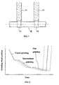
- Fig. 2 shows a relationship between a grinding wheel position and a time and the position explains an end of the grinding wheel surface so that Fig. 2 shows grinding process according to a moving trace of each grinding wheel.
- the grinding process has plural processes such as a coarse grinding, an intermediate grinding and a fine grinding.
- the in-process controller controls to transmit the grinding process to a next grinding at the end of each grinding, it appears time difference between the grinding by one grinding wheel (a solid line) and the grinding by the other grinding wheel (a dotted line or a dashed line). Ther efore, there happens either a delaying termination (the dashed line) or forward termination (the dotted line) of the other grinding wheel against the termination of said one grinding wheel to make said termination sequence different
- the workpiece especially a long workpiece intends to be bended on the basis of a stress on the workpiece by a grinding force or a grinding resistance. Because of the difference of the termination of sequence by each grinding wheel, a deflection of the bended workpiece is not stable at each end of final grinding process.
- a deflection of the bended workpiece is not stable at each end of final grinding process.
- the grinding shown in Fig. 2 next explains in the view point of the grinding by the other grinding wheel.
- the grinding by the other grinding wheel is terminated prior to the termination by one grinding wheel (see the dashed line) in the stage that the workpiece is largely bended by the grinding resistance of one grinding wheel.
- the grinding by the other grinding wheel is terminated after the termination by one grinding wheel (see the dotted line) in the stage that the grinding resistance of one grinding wheel is released.
- a dispersion of a grinding accuracy of a roundness or a straightness and so on is occurred.
- the grinding method comprises a step of terminating said grinding by a predetermined grinding wheel prior to a termination of said grinding by the other grinding wheel-Wherein, "the termination of the grinding” does not mean a time of the termination of the grinding by departing the grinding wheel from contacting with the workpiece but means a time of substantial completion that a removable amount is substantially zero.
- means for "terminating said grinding by a predetermined grinding wheel prior to a termination of said grinding by the other grinding wheel” is not limited to means explained in Claim 4 or Claim 5 but also is a various way as “a cutting sharpness of the predetermined grinding wheel is better than that of the other grinding wheel in any time", "a removable amount of a grinding portion by the other grinding wheel is larger than that by the predetermined grinding wheel", "a velocity of the grinding feed by the other grinding wheel is later than that by the predetermined grinding wheel” and so on.
- the workpiece since the grinding by predetermined grinding wheel is terminated prior to the termination by the other grinding wheel, the workpiece is maintaining in bending by the stress of the grinding portion by the other grinding wheel at the time of termination by the predetermined grinding wheel.
- every workpiece having plural grinding portions has a predictable bending of the grinding portion so that it can provide a grinding method substantially preventing an occurrence of a dispersion of a grinding accuracy.
- Said "same content of the grinding” means that the grinding is performed in same removable amount of grinding portions to grind said portions to same dimension and it has contents of grindings of the same finishing including a rough fine-grinding, a finish fine-grinding and so on.
- the present invention comprises a step of terminating the grinding by the predetermined grinding wheel prior to the termination by the other grinding wheel, it substantially restrains an occurrence of a dispersion of a grinding accuracy to be a useful for the grinding having the same contents.
- the grinding condition is "a velocity of the grinding feed", “a surface peripheral speed of the grinding wheel”, “a rotational speed of the workpiece rotated in a cylindrical grinding machine” and so on in which the present invention may change at least one condition.
- Said “result of measuring grinding portions” means the result to measure existing states of grinding portions such as a dimension, surface roughness and so on of grinding portions.
- the present invention sets the grinding wheel terminated at first, it can restrict the occurrence of the dispersion of the grinding accuracy to be able to set a suitable grinding condition in each grinding process.
- means of the termination by the predetermined grinding wheel prior to that by the other grinding wheel may be (1) the cutting sharpness of the predetermined grinding wheel is better than that of the other grinding wheel, (2) the removable amount of the grinding portion by the predetermined grinding wheel is set less than that by the other grinding wheel or (3) the velocity of the grinding feed of the other grinding wheel is slower than that of the predetermined grinding wheel and so on.
- said means (1) a state of the difference in cutting sharpness of each grinding wheel is maintained at any time so that the maintenance of each grinding wheel is vague.
- said means (2) since the removable amount by the other grinding wheel is larger, a total grinding time becomes large as a whole and a life of the grinding wheel becomes short.
- the feed velocity of the other grinding wheel is slow so that a quality by the other grinding wheel becomes relatively high needlessly to make the grinding time long.
- the grinding method of the present invention since the grinding method of the present invention has the difference in the removable amount in slower grinding feed velocity, the grinding by the predetermined grinding wheel is terminated at first so that the maintenance of the difference of the cutting sharpness in each grinding wheel is eliminated. Therefore, the grinding by the predetermined grinding wheel is terminated at first without large malfunction by simple means.
- the present invention has a time difference in grindings by the predetermined and the other grinding wheels so that the grinding by the predetermined grinding wheel at first. Therefore, the grinding by the predetermined grinding wheel is terminated at first without large malfunction by simple means as explained above.
- the predetermined and the other grinding wheels are retracted at same time so that it can make a stable release of a grinding stress by each grinding wheel,
- grinding wheels are retracted at the slow speed at first without rapid speed so that it can make a stable release of a grinding stress too.
- the retraction speed of the grinding wheel from the workpiece at first is selected from slow grinding feed speed of coarse grinding, intermediate grinding, fine grinding and so on, and is selected normal rapid feed speed in the grinding machine.
- a preferred embodiment of a grinding method according to the aforementioned invention will be described referring to Fig. 3 to Fig. 7.
- the embodiment of the present invention will be described on a cylindrical grinding machine, however it is not limited for the present invention to be applied to the cylindrical grinding machine but it can be applicable to other various grinding machines having plural grinding wheels moved individually each other.
- a cylindrical grinding machine 10 has a bed 20, two wheel slides 30a, 30b and a table 40 supporting a workpiece W on an upper side of the bed 20.
- the bed 20 consists of a main flame and said wheel slides 30a, 30b are equipped on left and right upper sides of the bed 20.
- Each of two supporting table 31a, 31b is slidably mounted on an upper side of the bed 20 in Z-axis direction (shown by an arrow Z) of a longitudinal direction of the workpiece W and each of said wheel slides 30a, 30b is slidably mounted on each upper side of said supporting tables 31a, 31b in X-axis direction (shown by an arrow X) of a radial direction of the workpiece W.
- Each supporting table 31a, 31b is individually moved through movement transmission mechanism 33a, 33b, such as a feed screw mechanism and so on, by servo motor mechanism 32a, 32b indexing a rotary angle precisely.
- E ach wheel slide 30a, 30b is individually moved through movement transmission mechanism 35a, 35b, such as feed screw mechanism and so on, by servo motor mechanism 34a, 34b indexing a rotary angle precisely. Therefore, each wheel slide is moved in X- and 2-axes directions each other relative to the table 40.
- Disk-shaped grinding wheels T1, T2 are rotatably mounted in wheel slides 30a, 30b each other to be rotated by drivers 36a, 36b, such as a motor and so on.
- the table 40 equips a headstock 41 on its one side and a tailstock 42 on the other side.
- a main spindle 43 is provided in the headstock 41 to be rotated by a driving mechanism 44, such as servo motor and so on, indexing a rotary angle precisely.
- the workpiece W is supported on the table 40 to be held on its one side by a chuck 45 mounted on the main spindle 43 and to be forced on its other side by a center 46 mounted on the tailstock 42.
- the workpiece W is rotated in a C-axis direction (shown by an arrow C) around a center axis of the main spindle 43.
- the workpiece W is a crankshaft.
- a grinding portion of the crankshaft is a crank journal W1 or a crankpin W2 to be simultaneously ground by said two grinding wheels T1, T2.
- the grinding portion is ground by the way of a plunge-cutting and it can be applicable to the way of a traverse-cutting and so on.
- the grinding portion is previously cut by a cutting of a lathe or a milling machine to remain a removable amount of successive grinding.
- Each of grinding portions ground by two grinding wheels T1, T2 has the same removable amount each other to be remained by previous cutting.
- Each of grinding portions is ground by the present invention to the same profile, same dimension and same surface roughness.
- a grinding of two grinding wheels T1, T2 consists of plural processes of a coarse grinding, an intermediate grinding and a fine grinding.
- Fig. 4 shows a relationship between a grinding wheel position and a time and the position explains an end of the grinding wheel surface so that Fig. 4 shows grinding processes according to a moving trace of each grinding wheel T1, T2.
- the grinding portion ground by the predetermined grinding wheel T1 is reached to a predetermined dimension before the grinding portion ground by the other grinding wheel T2 is reached to the predetermined dimension, and then the substantial grinding is terminated.
- the grinding by the predetermined grinding wheel T1 is terminated prior to a termination of the grinding by the other grinding wheel T2.
- Each process of grindings is performed by each same grinding wheel T1, T2.
- a predetermined surface roughness is kept by changing a velocity of grinding feed.
- the grinding wheels are advanced in a comparatively rapid velocity of the grinding feed and are stopped for a spark out grinding to keep a predetermined dimension and a predetermined surface roughness.
- the grinding wheels are advanced in a relatively slower velocity of the grinding feed than the rapid velocity and are stopped for a spark out grinding to keep a predetermined dimension and a predetermined surface roughness.
- the grinding wheels are advanced in a slower velocity of the grinding feed than the velocity in the intermediate grinding and are stopped in order to keep a final predetermined dimension and a final predetermined surface roughness.
- the final predetermined dimension and surface roughness are kept because of substantially slow velocity of the grinding feed.
- the spark out grinding of the other grinding wheel T2 is eliminated but the spark out grinding may be performed by the other grinding wheel T2.
- the grinding processes are performed by an in-process controller in which a real dimension of the grinding portion is measured in each grinding to control the driving of the wheel slides 30a, 30b by feed-backing the measured dimension.
- the driving of each wheel slide 30a, 30b is controlled to transmit to next grinding process at reaching to the predetermined dimension of the grinding portion.
- the in-process controller of each grinding by grinding wheels T1, T2 is synchronous in grindings by two wheels T1 and T2 in order to transmit simultaneously to next grinding process as shown in Fig. 4.
- the removable amount of grinding portion by the grinding wheel T1 is differ from the removable amount of grinding portion by the other grinding wheel T2 in certain grinding process in order to terminate the grinding by the grinding wheel T1 prior to the termination of the grinding by the other grinding wheel T2.
- the removable amount of the grinding portion by the other grinding wheel T2 is less than the removable amount of the grinding portion by the grinding wheel T1 to terminate the coarse grinding by the grinding wheel T2 in a stage that the remaining removable amount of the grinding portion by the other grinding wheel T2 is larger than that by the grinding wheel T1
- the grinding wheel T2 is waiting in a stage of the spark out grinding until the termination of the coarse grinding by grinding wheel T1. After terminations of coarse and spark out grindings of each grinding wheel T1, T2 each grinding process by grinding wheels T1, T2 is transmitted to next intermediate grinding.
- the intermediate grinding it can be set the same removable amount of grinding portion by grinding wheels T1 and T2.
- the removable amount of grinding by the other grinding wheel T2 is set to be larger than that by the grinding wheel T1 to terminate the intermediate grinding within a stage that the remaining removable amount of grinding portion by the other grinding wheel T2 is still larger than that by the grinding wheel T1 before the fine grinding of the final process.
- a difference between the remaining removable amount of grinding portion by two wheels after the intermediate grinding is smaller than a difference between the same prior to the intermediate grinding so that it restrains the remaining removable amount of grinding portion by the other grinding wheel T2 to be large wastefully in the fine grinding.
- the intermediate grinding by the grinding wheel T1 is terminated prior to that by the other grinding wheel T2.
- the grinding wheel T1 is waiting in a stage of the spark out grinding until the termination of the intermediate grinding by the other grinding wheel T2. After terminations of intermediate and spark out grindings by each grinding wheel T1, T2 each grinding process by grinding wheels T1, T2 is transmitted to next fine grinding.
- the fine grinding all remaining removable amount of grinding portion are removed in order to maintain a desirable dimension and surface roughness, because the remaining removable amount of grinding portion by the other grinding wheel T2 is larger than that by the grinding wheel T1 in the fine grinding the grinding portion by the grinding wheel T1 reaches to a predetermined dimension prior to the reach by the other grinding wheel T2.
- the difference between the remaining removable amounts of grinding portion by two grinding wheels T1 and T2 in a beginning of the fine grinding is set to terminate the fine grinding by the grinding wheel T1 prior to the termination by the other grinding wheel T2. Therefore, the grinding by the grinding wheel T1 is terminated prior the termination of the grinding by the other grinding wheel T2 every time in other grinding portion or in other workpiece W.
- the wheel slide 30a may be retracted in rapid feed to depart from the workpiece W.
- the grinding wheel T1 is remaining in contact with the workpiece W in the spark out grinding until the termination of the fine grinding by the other grinding wheel T2.
- each wheel slide 30a, 30b is retracted at the same time. In the beginning and ending of grindings by each grinding wheel T1, T2, movement of the wheel slides 30a, 30b is synchronous each other.
- a grinding by the grinding wheel T1 and a grinding by the other grinding wheel T2 are individually performed by an in-process controller without synchronousness each other.
- the individual grinding by each grinding wheel T1, T2 is controlled to be transmitted to next grinding process at the end of the coarse grinding, the intermediate grinding and the fine grinding.
- a removable amount of grinding portion by the grinding wheel T1 is set less than a removable amount of grinding portion by the other grinding wheel T2 in the coarse grinding.
- a removable amount of grinding portion by the other grinding wheel T2 in the intermediate grinding or in the fine grinding is larger than a removable amount of grinding portion by the grinding wheel T1.
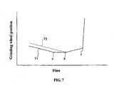
- a third embodiment of the present invention will be described referring to Fig. 6.
- a grinding by the grinding wheel T1 and a grinding by the other grinding wheel T2 are controlled individually by an in-process controller without the synchronousness.
- a r emovable amount of the grinding portion by said one grinding wheel is set also same to a removable amount by the other grinding wheel T2 in each of the coarse, the intermediate and the fine grinding, a grinding time by the other grinding wheel T2 delays from a grinding time by one grinding wheel T1 so that the grinding by the grinding wheel T1 is terminated prior to the termination by the grinding wheel T2.
- FIG. 7 shows only an end portion of grinding process and the other portion is the same to previous embodiments.
- the grinding wheel T1 After a termination of a fine grinding by the grinding wheel T1 (see a point a in Fig. 7), the grinding wheel T1 remains to contact with the workpiece without retraction immediately and both wheels are retracted at the same time when a fine grinding by the other grinding wheel T2 is terminated (see a point b).
- a velocity of the retraction of grinding wheels T1 and T2 are slow speed like a grinding feed speed, after passing a point c the velocity are changed to a normal rapid retraction speed.
- a grinding method comprises steps of simultaneously grinding plural grinding portions of a workpiece by plural grinding wheels T1, T2 moved individually each other, and terminating said grinding by a predetermined grinding wheel T1 prior to a termination of said grinding by the other grinding wheel T2.
- a content of the grinding by each grinding wheel T1, T2 can be same.
- a grinding condition in each grinding by each grinding wheel T1, T2 can be changed in accordance with a measuring result of the grinding portion in the grinding.
Landscapes
- Engineering & Computer Science (AREA)
- Mechanical Engineering (AREA)
- Constituent Portions Of Griding Lathes, Driving, Sensing And Control (AREA)
- Grinding Of Cylindrical And Plane Surfaces (AREA)
- Grinding And Polishing Of Tertiary Curved Surfaces And Surfaces With Complex Shapes (AREA)
Applications Claiming Priority (2)
| Application Number | Priority Date | Filing Date | Title |
|---|---|---|---|
| JP2002203642A JP3878519B2 (ja) | 2002-07-12 | 2002-07-12 | 研削方法 |
| JP2002203642 | 2002-07-12 |
Publications (2)
| Publication Number | Publication Date |
|---|---|
| EP1380385A1 true EP1380385A1 (fr) | 2004-01-14 |
| EP1380385B1 EP1380385B1 (fr) | 2012-05-02 |
Family
ID=29728526
Family Applications (1)
| Application Number | Title | Priority Date | Filing Date |
|---|---|---|---|
| EP03015801A Expired - Lifetime EP1380385B1 (fr) | 2002-07-12 | 2003-07-10 | Procédé pour meuler simultanément plusieurs parties d'une pièce |
Country Status (3)
| Country | Link |
|---|---|
| US (1) | US7037173B2 (fr) |
| EP (1) | EP1380385B1 (fr) |
| JP (1) | JP3878519B2 (fr) |
Cited By (1)
| Publication number | Priority date | Publication date | Assignee | Title |
|---|---|---|---|---|
| EP2181802A1 (fr) * | 2008-10-28 | 2010-05-05 | Jtekt Corporation | Meuleuse et procédé de broyage |
Families Citing this family (12)
| Publication number | Priority date | Publication date | Assignee | Title |
|---|---|---|---|---|
| JP4730944B2 (ja) * | 2004-06-04 | 2011-07-20 | コマツNtc株式会社 | 多頭研削盤及び多頭研削盤を用いた研削方法 |
| JP5058460B2 (ja) * | 2005-07-11 | 2012-10-24 | Ntn株式会社 | 研磨装置付き旋盤及びこれを用いて行う軸状ワークの加工方法 |
| CN101687303B (zh) * | 2007-06-13 | 2013-05-29 | Emag控股有限公司 | 用于磨削凸轮轴凸轮的方法和装置 |
| US8299743B2 (en) * | 2009-01-29 | 2012-10-30 | Jtekt Corporation | Machine tool and controlling method thereof |
| JP5359320B2 (ja) * | 2009-01-29 | 2013-12-04 | 株式会社ジェイテクト | 工作機械 |
| DE102009047913A1 (de) * | 2009-09-22 | 2011-03-31 | Schaudt Mikrosa Gmbh | Schleifmaschine zum Schleifen von Werkstücken |
| US8846107B2 (en) * | 2010-12-29 | 2014-09-30 | Ecolab Usa Inc. | In situ generation of peroxycarboxylic acids at alkaline pH, and methods of use thereof |
| DE102012012331B4 (de) * | 2011-07-28 | 2016-03-03 | Emag Holding Gmbh | Werkzeugmaschine |
| EP2769806B1 (fr) * | 2013-02-21 | 2014-12-17 | Supfina Grieshaber GmbH & Co. KG | Dispositif et système de finition de surface d'une pièce à usiner en forme de vilebrequin ou d'arbre à came |
| US11040430B2 (en) * | 2016-02-29 | 2021-06-22 | Charles Neff | Texture pattern for abrasive tool |
| CN110064971A (zh) | 2016-04-28 | 2019-07-30 | 株式会社捷太格特 | 机床系统以及表面粗糙度检测方法 |
| US10654144B2 (en) * | 2018-01-17 | 2020-05-19 | Dave Phelps | Spindle reconditioning system |
Citations (2)
| Publication number | Priority date | Publication date | Assignee | Title |
|---|---|---|---|---|
| EP1088621A2 (fr) | 1999-09-30 | 2001-04-04 | Toyoda Koki Kabushiki Kaisha | Procédé et dispositif pour usiner une pièce au moyen de plusieurs têtes d'outil |
| US6306018B1 (en) * | 1996-07-24 | 2001-10-23 | Unova U.K. Limited | Grinding methods and apparatus |
Family Cites Families (4)
| Publication number | Priority date | Publication date | Assignee | Title |
|---|---|---|---|---|
| US5371973A (en) * | 1992-09-30 | 1994-12-13 | Western Atlas Inc. | Grinding machine utilizing multiple, parallel, abrasive belts simultaneously grinding surfaces on a workpiece |
| US5529531A (en) * | 1994-12-23 | 1996-06-25 | Western Atlas Corporation | Tapered bearing for drive drum assembly of grinding machine utilizing multiple, parallel abrasive belts |
| US5975995A (en) * | 1997-06-25 | 1999-11-02 | Unova Ip Corp. | Machining apparatus and method |
| JP3649037B2 (ja) * | 1999-04-14 | 2005-05-18 | 豊田工機株式会社 | 複合研削盤 |
-
2002
- 2002-07-12 JP JP2002203642A patent/JP3878519B2/ja not_active Expired - Fee Related
-
2003
- 2003-07-10 EP EP03015801A patent/EP1380385B1/fr not_active Expired - Lifetime
- 2003-07-11 US US10/617,053 patent/US7037173B2/en not_active Expired - Lifetime
Patent Citations (2)
| Publication number | Priority date | Publication date | Assignee | Title |
|---|---|---|---|---|
| US6306018B1 (en) * | 1996-07-24 | 2001-10-23 | Unova U.K. Limited | Grinding methods and apparatus |
| EP1088621A2 (fr) | 1999-09-30 | 2001-04-04 | Toyoda Koki Kabushiki Kaisha | Procédé et dispositif pour usiner une pièce au moyen de plusieurs têtes d'outil |
Cited By (1)
| Publication number | Priority date | Publication date | Assignee | Title |
|---|---|---|---|---|
| EP2181802A1 (fr) * | 2008-10-28 | 2010-05-05 | Jtekt Corporation | Meuleuse et procédé de broyage |
Also Published As
| Publication number | Publication date |
|---|---|
| EP1380385B1 (fr) | 2012-05-02 |
| US7037173B2 (en) | 2006-05-02 |
| JP2004042199A (ja) | 2004-02-12 |
| JP3878519B2 (ja) | 2007-02-07 |
| US20040009741A1 (en) | 2004-01-15 |
Similar Documents
| Publication | Publication Date | Title |
|---|---|---|
| US8678881B2 (en) | Grinding center and method for simultaneous grinding of a plurality of bearings and end-side surfaces of crankshafts | |
| KR100553409B1 (ko) | 공작물의 연삭방법 및 장치 | |
| US8360819B2 (en) | Method for grinding a machine part, and grinding machine for carrying out said method | |
| EP1088621B1 (fr) | Procédé et dispositif pour usiner une pièce au moyen de plusieurs têtes d'outil | |
| US7037173B2 (en) | Method of grinding | |
| US20040074073A1 (en) | Numerical control (NC) processor with onboard grinding unit | |
| KR20160133494A (ko) | 대형 크랭크 샤프트를 연삭하는 방법 및 장치 | |
| CN101784368A (zh) | 用于同时研磨曲轴的多个轴承的研磨中心和方法 | |
| US5533931A (en) | Method and machine for grinding a workpiece | |
| EP1839809B2 (fr) | Procédé et dispositif de meulage | |
| US5766059A (en) | Method of grinding a workpiece | |
| EP1621287B1 (fr) | Procédé et dispositif pour meuler des cames à surface concave | |
| US5865667A (en) | Grinding machine | |
| US6852015B2 (en) | Method and apparatus for grinding workpiece surfaces to super-finish surface with micro oil pockets | |
| US7901268B2 (en) | Method for grinding journal section of workpiece | |
| JPH02284865A (ja) | 内面研削装置 | |
| JP2002103188A (ja) | 端面研削加工方法及び端面研削装置 | |
| JPH05162005A (ja) | バイト成形機能付き旋盤 | |
| JP2000218479A (ja) | 円筒研削方法及び装置 | |
| JPH01171743A (ja) | 研削加工方法 | |
| JP2001260019A (ja) | 研削装置及び研削方法 | |
| JPH05162068A (ja) | 内面研削におけるリトラクション量調整方法 | |
| JPH07108456A (ja) | 研削装置 | |
| JPH06278021A (ja) | 研削装置 | |
| JPH1044031A (ja) | 工作物の研削方法 |
Legal Events
| Date | Code | Title | Description |
|---|---|---|---|
| PUAI | Public reference made under article 153(3) epc to a published international application that has entered the european phase |
Free format text: ORIGINAL CODE: 0009012 |
|
| AK | Designated contracting states |
Kind code of ref document: A1 Designated state(s): AT BE BG CH CY CZ DE DK EE ES FI FR GB GR HU IE IT LI LU MC NL PT RO SE SI SK TR |
|
| AX | Request for extension of the european patent |
Extension state: AL LT LV MK |
|
| 17P | Request for examination filed |
Effective date: 20040625 |
|
| AKX | Designation fees paid |
Designated state(s): DE FR GB |
|
| 17Q | First examination report despatched |
Effective date: 20040927 |
|
| RAP1 | Party data changed (applicant data changed or rights of an application transferred) |
Owner name: JTEKT CORPORATION |
|
| 17Q | First examination report despatched |
Effective date: 20040927 |
|
| RIN1 | Information on inventor provided before grant (corrected) |
Inventor name: JTEKT CORPORATION |
|
| GRAP | Despatch of communication of intention to grant a patent |
Free format text: ORIGINAL CODE: EPIDOSNIGR1 |
|
| GRAS | Grant fee paid |
Free format text: ORIGINAL CODE: EPIDOSNIGR3 |
|
| GRAA | (expected) grant |
Free format text: ORIGINAL CODE: 0009210 |
|
| RBV | Designated contracting states (corrected) |
Designated state(s): DE FR |
|
| AK | Designated contracting states |
Kind code of ref document: B1 Designated state(s): DE FR |
|
| REG | Reference to a national code |
Ref country code: DE Ref legal event code: R096 Ref document number: 60340788 Country of ref document: DE Effective date: 20120705 |
|
| PLBE | No opposition filed within time limit |
Free format text: ORIGINAL CODE: 0009261 |
|
| STAA | Information on the status of an ep patent application or granted ep patent |
Free format text: STATUS: NO OPPOSITION FILED WITHIN TIME LIMIT |
|
| 26N | No opposition filed |
Effective date: 20130205 |
|
| REG | Reference to a national code |
Ref country code: DE Ref legal event code: R097 Ref document number: 60340788 Country of ref document: DE Effective date: 20130205 |
|
| REG | Reference to a national code |
Ref country code: FR Ref legal event code: PLFP Year of fee payment: 14 |
|
| REG | Reference to a national code |
Ref country code: FR Ref legal event code: PLFP Year of fee payment: 15 |
|
| PGFP | Annual fee paid to national office [announced via postgrant information from national office to epo] |
Ref country code: FR Payment date: 20170613 Year of fee payment: 15 |
|
| PG25 | Lapsed in a contracting state [announced via postgrant information from national office to epo] |
Ref country code: FR Free format text: LAPSE BECAUSE OF NON-PAYMENT OF DUE FEES Effective date: 20180731 |
|
| PGFP | Annual fee paid to national office [announced via postgrant information from national office to epo] |
Ref country code: DE Payment date: 20200630 Year of fee payment: 18 |
|
| REG | Reference to a national code |
Ref country code: DE Ref legal event code: R119 Ref document number: 60340788 Country of ref document: DE |
|
| PG25 | Lapsed in a contracting state [announced via postgrant information from national office to epo] |
Ref country code: DE Free format text: LAPSE BECAUSE OF NON-PAYMENT OF DUE FEES Effective date: 20220201 |