EP1380387A1 - Strahleinrichtung - Google Patents
Strahleinrichtung Download PDFInfo
- Publication number
- EP1380387A1 EP1380387A1 EP03014979A EP03014979A EP1380387A1 EP 1380387 A1 EP1380387 A1 EP 1380387A1 EP 03014979 A EP03014979 A EP 03014979A EP 03014979 A EP03014979 A EP 03014979A EP 1380387 A1 EP1380387 A1 EP 1380387A1
- Authority
- EP
- European Patent Office
- Prior art keywords
- guide sleeve
- sleeve
- centrifugal
- centrifugal wheel
- blasting
- Prior art date
- Legal status (The legal status is an assumption and is not a legal conclusion. Google has not performed a legal analysis and makes no representation as to the accuracy of the status listed.)
- Granted
Links
- 238000005270 abrasive blasting Methods 0.000 title 1
- 238000005422 blasting Methods 0.000 claims description 45
- 239000000463 material Substances 0.000 claims description 11
- 238000005299 abrasion Methods 0.000 claims description 8
- 238000003754 machining Methods 0.000 claims description 4
- 239000000919 ceramic Substances 0.000 claims description 3
- 239000002184 metal Substances 0.000 claims description 3
- 238000005086 pumping Methods 0.000 claims description 3
- 238000009826 distribution Methods 0.000 claims description 2
- 239000004576 sand Substances 0.000 abstract 5
- 239000003795 chemical substances by application Substances 0.000 description 15
- 239000000203 mixture Substances 0.000 description 6
- 239000008141 laxative Substances 0.000 description 3
- 230000002475 laxative effect Effects 0.000 description 3
- 230000002093 peripheral effect Effects 0.000 description 2
- 239000003082 abrasive agent Substances 0.000 description 1
- 238000004140 cleaning Methods 0.000 description 1
- 238000010276 construction Methods 0.000 description 1
- 239000000428 dust Substances 0.000 description 1
- 230000000694 effects Effects 0.000 description 1
- 239000012530 fluid Substances 0.000 description 1
- 230000005484 gravity Effects 0.000 description 1
- 230000007257 malfunction Effects 0.000 description 1
- 238000004519 manufacturing process Methods 0.000 description 1
- 238000000034 method Methods 0.000 description 1
- 238000003860 storage Methods 0.000 description 1
Images

Classifications
-
- B—PERFORMING OPERATIONS; TRANSPORTING
- B24—GRINDING; POLISHING
- B24C—ABRASIVE OR RELATED BLASTING WITH PARTICULATE MATERIAL
- B24C5/00—Devices or accessories for generating abrasive blasts
- B24C5/06—Impeller wheels; Rotor blades therefor
- B24C5/068—Transferring the abrasive particles from the feeding means onto the propeller blades, e.g. using central impellers
Definitions
- the present invention relates to a beam device for machining workpiece surfaces using a granular abrasive, with a rotatable Centrifugal wheel with centrifugal blades, with one that Centrifugal wheel with the exception of an abrasive discharge area surrounding centrifugal wheel housing, with a feed line for the feeding of the abrasive, with a the centrifugal wheel rotating radially inside the Centrifugal blades arranged in centrifugal blades, into which the supply line opens and with several breakthroughs in their scope, through which the blasting media supplied into the gaps between two neighboring centrifugal blades.
- a beam device of the type mentioned is from the utility model DE-U1 858 683 known. With this beam device the abrasive passes through a feed pipe towards the blasting agent inlet of the blasting device. Immediately before entering the beam device the supply line for the blasting medium opens into a Compressed air supply line. Through the through the compressed air supply line The blasting agent is supplied with compressed air accelerated and by a non-rotating, narrowing Nozzle tube towards the center of the centrifugal wheel promoted. The nozzle pipe ends immediately in front of you with the centrifugal wheel rotating feed wheel, which in its Scope has several openings, the passage of the blasting agent-air mixture in the radial direction serve outside.
- a sleeve-like Radially outside the nozzle tube and the metering wheel is a sleeve-like at a short distance from it Fixed housing.
- the sleeve-like housing has approximately congruent with the openings in the Allotment wheel an allotment recess in its extent, by which the blasting agent-air mixture continues radially outwards reaches the area of the rotating centrifugal wheel.
- the sleeve-like housing has a Ab technologicalaus brieflyung. This discharge opening is in the axial direction offset relative to the centrifugal wheel so that the Discharge recess seen in the axial direction in front of the centrifugal wheel is positioned.
- the laxative opening then opens in a space between the centrifugal wheel and a housing surrounding the centrifugal wheel is formed.
- the laxative recess is used here, an excess of to remove the supplied blasting agent-air mixture to blockages the beam device by an excess of to exclude the abrasive supplied.
- Such one Excess blasting media supplied can be relative here easily occur because the compressed air supplied for a effective promotion of abrasives in the center of the Centrifugal wheel ensures, in order to avoid a lack of abrasive in practice the supply of the abrasive generally preferred to be set a little higher than necessary becomes.
- This deliberate excess of fed Abrasive is here unless it is excessively large is not harmful because the excess of abrasive, as explained above, harmless through the laxative recess, but also for machining the workpiece surface useless, is dissipated.
- the object of the present invention is a beam device of the type mentioned create, with a simplified working method a more efficient Use of the abrasive used becomes.
- a simplification of the beam device according to the invention is achieved primarily by: their operation does not require the supply of compressed air, with which also the provision of production facilities of compressed air at the location where the jet device is used more is needed.
- By eliminating the compressed air can also appropriate line connections, such as Compressed air hoses, eliminated, which makes the handling of the Beam device is simplified.
- a particularly effective one Function of the beam device is achieved that through the air inlet opening or openings air into the incoming blasting medium in the guide sleeve initiated and in the center of the beam device with the Abrasive is mixed, making it very light and mixture of air and abrasive that can be conveyed with little resistance will be produced.
- the throughput can increase Blasting media through the blasting device with constant Drive power can be increased significantly, which also a corresponding increase in processing power, the one with the beam device Workpiece is achievable.
- the jet device provides the required amount of air with their already existing centrifugal wheel, without the Additional fan or additional requirement Air blades exist, so the construction of the Beam device advantageously remains simple.
- each air inlet opening has a cross section that is small compared to the cross section of the opening for the abrasive in the circumference of the guide sleeve. In this way a compact design is guaranteed because for the Air inlet openings seen in the axial direction of the guide sleeve only a relatively short section of their length is required becomes.
- each air inlet opening has a round cross section with rounded front and rear ends.
- the opening in the circumference of the guide sleeve through which the blasting agent-air mixture in the radial direction Funding from the inside out is preferred provided that this is a window with essentially right-angled corners that is in the circumferential direction the guide sleeve over an angle between about 30 ° and extends 60 °.
- the throughput can be at the said angle of the blasting agent-air mixture.
- the centrifugal wheel housing at a distance from an outer housing is surrounded, with the exception of an opening for the Abrasive discharge area of the blast wheel housing closed is, with a gap between Centrifugal wheel housing and outer housing air, preferably from an area next to the blasting agent ejection area, can be guided to the guide sleeve.
- the Blasting device is advantageous to the blasting agent Air to be mixed from an area close to the blasting agent ejection area deducted, which is advantageous a certain Deduction of generated dust from a workpiece surface material removed. So that becomes a cleaner operation of the beam device in comparison achieved to common facilities.
- the centrifugal wheel and the distributor sleeve by a motor flanged to the outside of the outer housing are drivable, the motor on an end wall of the outer housing is arranged, the supply line for the abrasive in the opposite, other end wall of the outer housing and the supply line as Tube formed with a tube flange and detachable with the associated end wall is connected.
- the invention further proposes that the supply line forming tube in an arc between about 30 ° and 60 ° coming into the outer casing from above and pointing substantially in or near the axial direction the starting area of the distributor sleeve ends.
- Gravity can be exploited, which special conveyors dispensable on the supply line side makes.
- the end region of the feed line facing the distributor sleeve is formed with a step, an upper Part of the end area shorter and a lower part of the end area is trained longer.
- the guide sleeve, as well as the distributor sleeve and the Centrifugal blades of the centrifugal wheel in operation Wear is for the purpose of easy interchangeability the guide sleeve provided that this on her supply end on the supply side with a mounting flange is formed, which is detachably connected to the outer housing is.
- this preferably consists of two interconnected parts, namely one hollow cylindrical sleeve part made of an abrasion-resistant material and from an associated flange part from a less abrasion-resistant, easier to edit material.
- This is only advantageous for those who actually use the hollow cylindrical sleeve part stressed the abrasion-resistant, much more expensive material used, while for the one not used by the abrasive Part of the guide sleeve a less abrasion-resistant, lighter editable and also cheaper material used becomes.
- the guide sleeve or possibly at least their sleeve part a sintered metal or ceramic. These materials are particularly resistant to abrasion and therefore particularly good for the heavily used guide sleeve or its hollow cylindrical one Suitable sleeve part.
- FIG. 1 of the drawing shows a beam device 1 in a cross section running in a vertical plane.
- the beam device 1 comprises an outer housing 10, the formed by two end walls 11, 12 and a peripheral wall 13 is.
- a Centrifugal wheel housing 20 Inside the outer housing 10 is a Centrifugal wheel housing 20 arranged, in which a centrifugal wheel 2 is housed.
- the centrifugal wheel 2 is through only a small part visible on the right in FIG. 1
- Drive motor 27 via a drive shaft 28 Axis of rotation 29 drivable.
- the motor 27 is by means of a Motor flange 27 'releasably with the rest of the beam device 1 connected.
- the centrifugal wheel housing 20 has two end walls 21, 22 and a peripheral wall 23. Downward is the centrifugal wheel housing 20 open and forms an abrasive discharge area there 26. With its lower part, this protrudes Centrifugal wheel housing 20 through an opening 16 in one Base plate 14, which is part of the outer housing 10 forms.
- the lower part of the beam device 1 forms a guide plate 15, which is congruent in its center with the blasting agent ejection area 26 is open and that of guiding the beam device 1 via a machining workpiece.
- the centrifugal wheel 2 is interchangeable Centrifugal blades 24 loaded in the radial direction are arranged pointing.
- the centrifugal wheel also carries 2 in its center a distributor sleeve 25 which in its Scope with one or more openings 25 ' Passage of blasting media is provided. Because of your Connection with the centrifugal wheel 2 rotates the distributor sleeve 25 together with the centrifugal wheel 2 in operation the beam device 1.
- the Guide sleeve 3 has a flange part 21, by means of which Guide sleeve 3 with the left end wall 11 in FIG Outer housing 10 is detachably connected.
- the guide sleeve 3 is therefore fixed within the beam device 1 arranged and does not rotate.
- the guide sleeve 3 has in its wall has an opening 32 which is substantially is the same size as the openings 25 'in the distributor sleeve 25.
- the guide sleeve 3 in its wall several smaller air inlet openings 33, which is axially offset towards the left end wall 11 are so that they are axially outside the range of motion the centrifugal blades 24 lie.
- the jet device 1 further comprises a feed line 4 for the abrasive.
- the feed line 4 has the shape here of a curved pipe socket that comes from above Describes arc of about 60 ° into the device 1.
- the free end of the feed line 4 is a connecting flange for a feed line not shown here executed from a blasting agent storage container.
- the inner end 42 of the feed line 4 has a step 43 formed with the end portion 42 in its lower Part longer and shorter in its upper part is. The lower, longer part of the inner end portion 42 the lead 4 protrudes into the interior of the distributor sleeve 25th
- the blasting agent arrives during operation of the blasting device 1 in the sense of the drawn on the outer connecting flange 40 Arrow through the feed line 4 into the interior of the Distribution sleeve 25, this supply of the abrasive done without the use of compressed air.
- the blasting agent arrives from the inside of the distributor sleeve 25 through the Openings 25 'and through the opening 32 of the Guide sleeve 3 in the radial direction outwards into the spaces between two neighboring centrifugal blades 24 of the centrifugal wheel 2.
- the rotating centrifugal wheel 2 accelerates the blasting medium and throws it at high speed Speed through the abrasive discharge area 26 out. Then the abrasive hits one to be processed Workpiece surface, for example around there to carry out a surface cleaning.
- the rotating centrifugal wheel 2 with its centrifugal blades 24 acts in the illustrated beam device 1 at the same time as a radial compressor.
- the air from the inside of the centrifugal wheel housing 20 is through the centrifugal blades 24 also accelerated and together with the Blasting media through the blasting agent ejection area 26 promoted outside. This creates in the center of the centrifugal wheel a negative pressure. This ensures that air passes through a gap 17 between the outer housing 10 and the Centrifugal wheel housing 20 from the area below the base plate 14 flows to the center of the beam device 1.
- the inflowing air first passes through the air inlet openings 33 of the guide sleeve 3 and flows then partly in the gap between the guide sleeve 3 and rotating distributor sleeve 25 and partly inside the distributor sleeve 25. Mixes in both areas the inflowing air with the supplied blasting agent and thus makes the abrasive easier to move.
- the same drive power of the Centrifugal wheel 2 increases the throughput of abrasive, thereby a corresponding increase in work performance the beam device 1 on a workpiece surface is achieved. None will be advantageous for this Compressed air source and no separate or integrated blower needs what the beam device 1 advantageous just keeps.
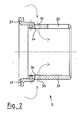
- Figure 2 of the drawing also shows a vertical cross section the guide sleeve 3 as part of the beam device 1 from Figure 1.
- Figure 2 illustrates the hollow cylindrical Shape of the guide sleeve 3.
- the guide sleeve 3 consists of two parts, namely a sleeve part 30 and a flange part 31. These two parts 30, 31 are firmly connected to each other by means of a rivet connection.
- the opening is in the sleeve part 30 32, which has the shape of a relatively large window and positioned relatively close to the right end of the guide sleeve 3 is.
- the air inlet openings 33 are provided in the sleeve part 30.
- the air inlet openings 33 are here with a round cross section and with roundings 34 on the inside and formed at the outer end to be as smooth as possible To allow air flow.
- the division of the guide sleeve in the two parts 30, 31 allows the use of special Materials for the two parts.
- the sleeve part 30 consists preferably of a particularly wear-resistant Material, for example sintered metal or ceramic, there this sleeve part 30 is heavily used by the blasting agent becomes.
- the one not used by the blasting agent Flange part 31 can be made from a less abrasion-resistant and to be made more easily editable material.
Landscapes
- Engineering & Computer Science (AREA)
- Mechanical Engineering (AREA)
- Structures Of Non-Positive Displacement Pumps (AREA)
Abstract
Description
- daß die Zuführung des Strahlmittels eine druckluftlose Zuführung ist,
- daß zwischen der Verteilerhülse und dem radial inneren Ende der Schleuderschaufeln eine verdrehfeste Leithülse angeordnet ist,
- daß die Leithülse mit wenigstens einer Durchbrechung in ihrem Umfang ausgeführt ist, durch die das zugeführte Strahlmittel nach seinem Durchtritt durch die Durchbrechungen in der Verteilerhülse in die Zwischenräume zwischen den je zwei benachbarten Schleuderschaufeln (24) gelangt, und
- daß die Leithülse weiterhin mit wenigstens einer Lufteinlaßöffnung in ihrem Umfang ausgeführt ist, die in Axialrichtung gesehen außerhalb des Schleuderradgehäuses liegt und durch die bei rotierendem Schleuderrad durch dessen Pumpwirkung Luft von außen her in die Leithülse einleitbar und dem Strahlmittel zumischbar ist.
- Figur
- 1 eine Strahleinrichtung im Vertikalschnitt und
- Figur 2
- eine Leithülse als Teil der Strahleinrichtung aus Figur 1, ebenfalls im Vertikalschnitt, in vergrößerter Darstellung.
Claims (12)
- Strahleinrichtung (1) für die Bearbeitung von Werkstückoberflächen mittels eines körnigen Strahlmittels, mit einem drehantreibbaren Schleuderrad (2) mit Schleuderschaufeln (24), mit einem das Schleuderrad (2) mit Ausnahme eines Strahlmittelauswurfbereichs (26) umgebenden Schleuderradgehäuse (20), mit einer Zuleitung (4) für eine druckluftlose Zuführung des Strahlmittels, mit einer mit dem Schleuderrad (2) rotierenden, radial innerhalb der Schleuderschaufeln (24) angeordneten, konzentrischen Verteilerhülse (25), in die die Zuführleitung (4) einmündet und die mit mehreren Durchbrechungen (25') in ihrem Umfang ausgeführt ist, durch die das zugeführte Strahlmittel in die Zwischenräume zwischen je zwei benachbarten Schleuderschaufeln (24) gelangt,
dadurch gekennzeichnet,daß zwischen der Verteilerhülse (25) und dem radial inneren Ende (24') der Schleuderschaufeln (24) eine verdrehfeste Leithülse (3) angeordnet ist,daß die Leithülse (3) mit wenigstens einer Durchbrechung (32) in ihrem Umfang ausgeführt ist, durch die das zugeführte Strahlmittel nach seinem Durchtritt durch die Durchbrechungen (25') in der Verteilerhülse (25) in die Zwischenräume zwischen den je zwei benachbarten Schleuderschaufeln (24) gelangt, unddaß die Leithülse (3) weiterhin mit wenigstens einer Lufteinlaßöffnung (33) in ihrem Umfang ausgeführt ist, die in Axialrichtung gesehen außerhalb des Schleuderradgehäuses (20) liegt und durch die bei rotierendem Schleuderrad (2) durch dessen Pumpwirkung Luft von außen her in die Leithülse (3) einleitbar und dem Strahlmittel zumischbar ist. - Strahleinrichtung nach Anspruch 1, dadurch gekennzeichnet, daß in der Leithülse (3) über deren Umfang verteilt mehrere Lufteinlaßöffnungen (33) vorgesehen sind.
- Strahleinrichtung nach Anspruch 1 oder 2, dadurch gekennzeichnet, daß jede Lufteinlaßöffnung (33) einen Querschnitt aufweist, der klein ist gegenüber dem Querschnitt der Durchbrechung (32) für das Strahlmittel im Umfang der Leithülse (3).
- Strahleinrichtung nach Anspruch 3, dadurch gekennzeichnet, daß jede Lufteinlaßöffnung (33) einen runden Querschnitt mit ausgerundetem vorderen und hinteren Ende (34) aufweist.
- Strahleinrichtung nach einem der vorangehenden Ansprüche, dadurch gekennzeichnet, daß die Durchbrechung (32) im Umfang der Leithülse (3) ein Fenster mit im wesentlichen rechtwinkligen Ecken ist, das sich in Umfangsrichtung der Leithülse (3) über einen Winkel zwischen etwa 30° und 60° erstreckt.
- Strahleinrichtung nach einem der vorangehenden Ansprüche, dadurch gekennzeichnet, daß das Schleuderradgehäuse (20) mit Abstand von einem Außengehäuse (10) umgeben ist, das mit Ausnahme einer Öffnung (16) für den Strahlmittelauswurfbereich (26) des Schleuderradgehäuses (20) geschlossen ist, wobei durch einen Spaltraum (17) zwischen Schleuderradgehäuse (20) und Außengehäuse (10) Luft, vorzugsweise aus einem Bereich neben dem Strahlmittelauswurfbereich (26), zur Leithülse (3) führbar ist.
- Strahleinrichtung nach Anspruch 6, dadurch gekennzeichnet, daß das Schleuderrad (2) und die Verteilerhülse (25) durch einen außen an das Außengehäuse (10) angeflanschten Motor (27) antreibbar sind, wobei der Motor (27) an einer Stirnwand (12) des Außengehäuses (10) angeordnet ist, wobei die Zuleitung (4) in der entgegengesetzten, anderen Stirnwand (11) des Außengehäuses (10) liegt und wobei die Zuleitung (4) als Rohr mit einem Rohrflansch (41) ausgebildet und lösbar mit der zugehörigen Stirnwand (11) verbunden ist.
- Strahleinrichtung nach Anspruch 7, dadurch gekennzeichnet, daß das die Zuleitung (4) bildende Rohr in einem Bogen zwischen etwa 30 ° und 60°gekrümmt von oben kommend in das Außengehäuse (10) verläuft und im wesentlichen in Axialrichtung weisend im oder nahe dem Anfangsbereich der Verteilerhülse (25) endet.
- Strahleinrichtung nach Anspruch 8, dadurch gekennzeichnet, daß der der Verteilerhülse (25) zugewandte Endbereich (42) der Zuleitung (4) mit einer Stufe (43) ausgebildet ist, wobei ein oberer Teil des Endbereichs (42) kürzer und ein unterer Teil des Endbereichs (42) länger ausgebildet ist.
- Strahleinrichtung nach einem der Ansprüche 6 bis 9, dadurch gekennzeichnet, daß die Leithülse (3) an ihrem zuleitungsseitigen Stirnende mit einem Montageflansch (31) ausgebildet ist, der lösbar mit dem Außengehäuse (10) verbunden ist.
- Strahleinrichtung nach Anspruch 10, dadurch gekennzeichnet, daß die Leithülse (3) aus zwei miteinander verbundenen Teilen (30, 31) besteht, nämlich aus einem hohlzylindrischen Hülsenteil (30) aus einem abriebfesten Material und aus einem damit verbundenen Flanschteil (31) aus einem weniger abriebfesten, leichter bearbeitbaren Material.
- Strahleinrichtung nach einem der vorangehenden Ansprüche, dadurch gekennzeichnet, daß die Leithülse (3) oder gegebenenfalls zumindest deren Hülsenteil (30) aus einem Sintermetall oder aus Keramik besteht.
Applications Claiming Priority (2)
| Application Number | Priority Date | Filing Date | Title |
|---|---|---|---|
| DE10231482A DE10231482A1 (de) | 2002-07-12 | 2002-07-12 | Strahleinrichtung |
| DE10231482 | 2002-07-12 |
Publications (3)
| Publication Number | Publication Date |
|---|---|
| EP1380387A1 true EP1380387A1 (de) | 2004-01-14 |
| EP1380387B1 EP1380387B1 (de) | 2005-05-18 |
| EP1380387B9 EP1380387B9 (de) | 2005-09-28 |
Family
ID=29723858
Family Applications (1)
| Application Number | Title | Priority Date | Filing Date |
|---|---|---|---|
| EP03014979A Expired - Lifetime EP1380387B9 (de) | 2002-07-12 | 2003-07-02 | Strahleinrichtung |
Country Status (2)
| Country | Link |
|---|---|
| EP (1) | EP1380387B9 (de) |
| DE (2) | DE10231482A1 (de) |
Cited By (2)
| Publication number | Priority date | Publication date | Assignee | Title |
|---|---|---|---|---|
| CN115338782A (zh) * | 2022-08-29 | 2022-11-15 | 浙江柯蓝工贸有限公司 | 一种金属锅体高硬度耐蚀表面处理用喷砂机及其喷砂方法 |
| CN117655935A (zh) * | 2023-12-08 | 2024-03-08 | 江苏天坦能源有限公司 | 一种光伏边框支架耐腐蚀涂层镀覆处理装置 |
Families Citing this family (1)
| Publication number | Priority date | Publication date | Assignee | Title |
|---|---|---|---|---|
| CN103567886B (zh) * | 2013-11-06 | 2017-01-04 | 江苏龙城铸造机械科技有限公司 | 一种型材的横向排列、纵向分步进给上料装置及方法 |
Citations (4)
| Publication number | Priority date | Publication date | Assignee | Title |
|---|---|---|---|---|
| FR1390286A (fr) * | 1964-01-04 | 1965-02-26 | A Sisson Lehmann Ets | Perfectionnements aux dispositifs de projection, par turbines, de particules solides |
| US3867791A (en) * | 1974-05-13 | 1975-02-25 | James R Goff | Abrasive blasting machine |
| US5092084A (en) * | 1988-04-27 | 1992-03-03 | Schlick-Roto-Jet Maschinenbau Gmbh | Method and apparatus for removing coatings from plastic laminates |
| EP0673719A1 (de) * | 1994-03-26 | 1995-09-27 | SCHLICK-Roto-Jet Maschinenbau GmbH | Schleuderrad mit fixierten Schleuderrad-Schaufeln |
Family Cites Families (1)
| Publication number | Priority date | Publication date | Assignee | Title |
|---|---|---|---|---|
| DE4410629A1 (de) * | 1994-03-26 | 1995-09-28 | Schlick Roto Jet Masch | Schleuderrad mit Verteilerrad |
-
2002
- 2002-07-12 DE DE10231482A patent/DE10231482A1/de not_active Withdrawn
-
2003
- 2003-07-02 EP EP03014979A patent/EP1380387B9/de not_active Expired - Lifetime
- 2003-07-02 DE DE50300550T patent/DE50300550D1/de not_active Expired - Lifetime
Patent Citations (4)
| Publication number | Priority date | Publication date | Assignee | Title |
|---|---|---|---|---|
| FR1390286A (fr) * | 1964-01-04 | 1965-02-26 | A Sisson Lehmann Ets | Perfectionnements aux dispositifs de projection, par turbines, de particules solides |
| US3867791A (en) * | 1974-05-13 | 1975-02-25 | James R Goff | Abrasive blasting machine |
| US5092084A (en) * | 1988-04-27 | 1992-03-03 | Schlick-Roto-Jet Maschinenbau Gmbh | Method and apparatus for removing coatings from plastic laminates |
| EP0673719A1 (de) * | 1994-03-26 | 1995-09-27 | SCHLICK-Roto-Jet Maschinenbau GmbH | Schleuderrad mit fixierten Schleuderrad-Schaufeln |
Cited By (2)
| Publication number | Priority date | Publication date | Assignee | Title |
|---|---|---|---|---|
| CN115338782A (zh) * | 2022-08-29 | 2022-11-15 | 浙江柯蓝工贸有限公司 | 一种金属锅体高硬度耐蚀表面处理用喷砂机及其喷砂方法 |
| CN117655935A (zh) * | 2023-12-08 | 2024-03-08 | 江苏天坦能源有限公司 | 一种光伏边框支架耐腐蚀涂层镀覆处理装置 |
Also Published As
| Publication number | Publication date |
|---|---|
| EP1380387B1 (de) | 2005-05-18 |
| DE10231482A1 (de) | 2004-01-29 |
| DE50300550D1 (de) | 2005-06-23 |
| EP1380387B9 (de) | 2005-09-28 |
Similar Documents
| Publication | Publication Date | Title |
|---|---|---|
| DE4006604C2 (de) | ||
| DE4429473C2 (de) | Windsichter | |
| EP0224527A1 (de) | Vorrichtung zum umwandeln einer fluidstr mung | |
| DE2149210A1 (de) | Durch unter Druck stehendes Fluid angetriebene Turbine | |
| DE19962049C2 (de) | Wirbelstrommühle | |
| DE754878C (de) | Vorrichtung zum Veraendern der Strahlrichtung an Sandputzmaschinen mit frei auswerfendem Schleuderrad | |
| DE102006011663A1 (de) | Angetriebenes Werkzeug mit Staubsammelfunktion | |
| EP1704369B1 (de) | Zellenradschleuse | |
| EP1380387B1 (de) | Strahleinrichtung | |
| EP1832386B1 (de) | Schleifrad zur spanabhebenden Bearbeitung von Gegenständen, insbesondere von natürlichen oder künstlichen Steinen | |
| DE19651417B4 (de) | Auflöseeinrichtung für Offenend-Spinnmaschinen | |
| DE2656040C2 (de) | Radialgebläse mit einer Vorrichtung zur Steuerung der Fördermenge von Gasen | |
| DE2714308C2 (de) | ||
| EP1555068B1 (de) | Trennwand für eine Rohrmühle und Mahlverfahren unter Verwendung dieser Mühle | |
| CH623770A5 (de) | ||
| EP1384554B1 (de) | Strahleinrichtung | |
| DE2304884C2 (de) | Vorrichtung zum koninuierlichen Beleimen von Spänen | |
| EP1795758A1 (de) | Laufrad für ein Pumpenaggregat und Pumpenaggregat | |
| EP1752658B1 (de) | Durchströmturbine mit Tangential-Laufrad | |
| DE19804809C1 (de) | Gegenstrom-Naßklassiervorrichtung und Verfahren zum Naßklassieren | |
| DE20108844U1 (de) | Zellenradschleuse | |
| DE507881C (de) | Geblaese zur Foerderung von sperrigem Gut | |
| EP0534483A2 (de) | Turbo-Fliehkraftsichter | |
| DE29522294U1 (de) | Rotationsstrahlgerät | |
| EP1787754A1 (de) | Gehäuse für ein Schleifrad |
Legal Events
| Date | Code | Title | Description |
|---|---|---|---|
| PUAI | Public reference made under article 153(3) epc to a published international application that has entered the european phase |
Free format text: ORIGINAL CODE: 0009012 |
|
| AK | Designated contracting states |
Kind code of ref document: A1 Designated state(s): AT BE BG CH CY CZ DE DK EE ES FI FR GB GR HU IE IT LI LU MC NL PT RO SE SI SK TR |
|
| AX | Request for extension of the european patent |
Extension state: AL LT LV MK |
|
| 17P | Request for examination filed |
Effective date: 20040617 |
|
| AKX | Designation fees paid |
Designated state(s): BE DE FR GB IT NL |
|
| GRAP | Despatch of communication of intention to grant a patent |
Free format text: ORIGINAL CODE: EPIDOSNIGR1 |
|
| GRAS | Grant fee paid |
Free format text: ORIGINAL CODE: EPIDOSNIGR3 |
|
| GRAA | (expected) grant |
Free format text: ORIGINAL CODE: 0009210 |
|
| AK | Designated contracting states |
Kind code of ref document: B1 Designated state(s): BE DE FR GB IT NL |
|
| REG | Reference to a national code |
Ref country code: GB Ref legal event code: FG4D Free format text: NOT ENGLISH |
|
| REG | Reference to a national code |
Ref country code: IE Ref legal event code: FG4D Free format text: LANGUAGE OF EP DOCUMENT: GERMAN |
|
| REF | Corresponds to: |
Ref document number: 50300550 Country of ref document: DE Date of ref document: 20050623 Kind code of ref document: P |
|
| PG25 | Lapsed in a contracting state [announced via postgrant information from national office to epo] |
Ref country code: IT Free format text: LAPSE BECAUSE OF NON-PAYMENT OF DUE FEES Effective date: 20050702 |
|
| PG25 | Lapsed in a contracting state [announced via postgrant information from national office to epo] |
Ref country code: BE Free format text: LAPSE BECAUSE OF NON-PAYMENT OF DUE FEES Effective date: 20050731 |
|
| GBT | Gb: translation of ep patent filed (gb section 77(6)(a)/1977) |
Effective date: 20050816 |
|
| PLBE | No opposition filed within time limit |
Free format text: ORIGINAL CODE: 0009261 |
|
| STAA | Information on the status of an ep patent application or granted ep patent |
Free format text: STATUS: NO OPPOSITION FILED WITHIN TIME LIMIT |
|
| ET | Fr: translation filed | ||
| 26N | No opposition filed |
Effective date: 20060221 |
|
| BERE | Be: lapsed |
Owner name: SCHLICK, JENNIFER Effective date: 20050731 |
|
| PGRI | Patent reinstated in contracting state [announced from national office to epo] |
Ref country code: IT Effective date: 20091201 |
|
| PGFP | Annual fee paid to national office [announced via postgrant information from national office to epo] |
Ref country code: GB Payment date: 20130626 Year of fee payment: 11 |
|
| PGFP | Annual fee paid to national office [announced via postgrant information from national office to epo] |
Ref country code: NL Payment date: 20130710 Year of fee payment: 11 Ref country code: DE Payment date: 20130913 Year of fee payment: 11 |
|
| PGFP | Annual fee paid to national office [announced via postgrant information from national office to epo] |
Ref country code: FR Payment date: 20130724 Year of fee payment: 11 |
|
| PGFP | Annual fee paid to national office [announced via postgrant information from national office to epo] |
Ref country code: IT Payment date: 20130712 Year of fee payment: 11 |
|
| REG | Reference to a national code |
Ref country code: DE Ref legal event code: R119 Ref document number: 50300550 Country of ref document: DE |
|
| REG | Reference to a national code |
Ref country code: NL Ref legal event code: V1 Effective date: 20150201 |
|
| GBPC | Gb: european patent ceased through non-payment of renewal fee |
Effective date: 20140702 |
|
| PG25 | Lapsed in a contracting state [announced via postgrant information from national office to epo] |
Ref country code: NL Free format text: LAPSE BECAUSE OF NON-PAYMENT OF DUE FEES Effective date: 20150201 |
|
| REG | Reference to a national code |
Ref country code: FR Ref legal event code: ST Effective date: 20150331 |
|
| PG25 | Lapsed in a contracting state [announced via postgrant information from national office to epo] |
Ref country code: IT Free format text: LAPSE BECAUSE OF NON-PAYMENT OF DUE FEES Effective date: 20140702 Ref country code: DE Free format text: LAPSE BECAUSE OF NON-PAYMENT OF DUE FEES Effective date: 20150203 |
|
| REG | Reference to a national code |
Ref country code: DE Ref legal event code: R119 Ref document number: 50300550 Country of ref document: DE Effective date: 20150203 |
|
| PG25 | Lapsed in a contracting state [announced via postgrant information from national office to epo] |
Ref country code: FR Free format text: LAPSE BECAUSE OF NON-PAYMENT OF DUE FEES Effective date: 20140731 Ref country code: GB Free format text: LAPSE BECAUSE OF NON-PAYMENT OF DUE FEES Effective date: 20140702 |