EP1380390A2 - Ratschenschlüssel - Google Patents
Ratschenschlüssel Download PDFInfo
- Publication number
- EP1380390A2 EP1380390A2 EP03102068A EP03102068A EP1380390A2 EP 1380390 A2 EP1380390 A2 EP 1380390A2 EP 03102068 A EP03102068 A EP 03102068A EP 03102068 A EP03102068 A EP 03102068A EP 1380390 A2 EP1380390 A2 EP 1380390A2
- Authority
- EP
- European Patent Office
- Prior art keywords
- wedge
- retainer
- wrench
- region
- faces
- Prior art date
- Legal status (The legal status is an assumption and is not a legal conclusion. Google has not performed a legal analysis and makes no representation as to the accuracy of the status listed.)
- Withdrawn
Links
Images




Classifications
-
- B—PERFORMING OPERATIONS; TRANSPORTING
- B25—HAND TOOLS; PORTABLE POWER-DRIVEN TOOLS; MANIPULATORS
- B25B—TOOLS OR BENCH DEVICES NOT OTHERWISE PROVIDED FOR, FOR FASTENING, CONNECTING, DISENGAGING, OR HOLDING
- B25B13/00—Spanners; Wrenches
- B25B13/46—Spanners; Wrenches of the ratchet type, for providing a free return stroke of the handle
-
- B—PERFORMING OPERATIONS; TRANSPORTING
- B25—HAND TOOLS; PORTABLE POWER-DRIVEN TOOLS; MANIPULATORS
- B25B—TOOLS OR BENCH DEVICES NOT OTHERWISE PROVIDED FOR, FOR FASTENING, CONNECTING, DISENGAGING, OR HOLDING
- B25B13/00—Spanners; Wrenches
- B25B13/48—Spanners; Wrenches for special purposes
- B25B13/50—Spanners; Wrenches for special purposes for operating on work of special profile, e.g. pipes
- B25B13/5008—Spanners; Wrenches for special purposes for operating on work of special profile, e.g. pipes for operating on pipes or cylindrical objects
- B25B13/5083—Spanners; Wrenches for special purposes for operating on work of special profile, e.g. pipes for operating on pipes or cylindrical objects by internally gripping the pipe
-
- B—PERFORMING OPERATIONS; TRANSPORTING
- B25—HAND TOOLS; PORTABLE POWER-DRIVEN TOOLS; MANIPULATORS
- B25B—TOOLS OR BENCH DEVICES NOT OTHERWISE PROVIDED FOR, FOR FASTENING, CONNECTING, DISENGAGING, OR HOLDING
- B25B13/00—Spanners; Wrenches
- B25B13/46—Spanners; Wrenches of the ratchet type, for providing a free return stroke of the handle
- B25B13/461—Spanners; Wrenches of the ratchet type, for providing a free return stroke of the handle with concentric driving and driven member
- B25B13/462—Spanners; Wrenches of the ratchet type, for providing a free return stroke of the handle with concentric driving and driven member the ratchet parts engaging in a direction radial to the tool operating axis
-
- B—PERFORMING OPERATIONS; TRANSPORTING
- B25—HAND TOOLS; PORTABLE POWER-DRIVEN TOOLS; MANIPULATORS
- B25B—TOOLS OR BENCH DEVICES NOT OTHERWISE PROVIDED FOR, FOR FASTENING, CONNECTING, DISENGAGING, OR HOLDING
- B25B13/00—Spanners; Wrenches
- B25B13/48—Spanners; Wrenches for special purposes
- B25B13/50—Spanners; Wrenches for special purposes for operating on work of special profile, e.g. pipes
- B25B13/5008—Spanners; Wrenches for special purposes for operating on work of special profile, e.g. pipes for operating on pipes or cylindrical objects
- B25B13/5016—Spanners; Wrenches for special purposes for operating on work of special profile, e.g. pipes for operating on pipes or cylindrical objects by externally gripping the pipe
- B25B13/5066—Spanners; Wrenches for special purposes for operating on work of special profile, e.g. pipes for operating on pipes or cylindrical objects by externally gripping the pipe using rollers moving along radial cams in a cage structure at least partially surrounding the pipe
-
- B—PERFORMING OPERATIONS; TRANSPORTING
- B25—HAND TOOLS; PORTABLE POWER-DRIVEN TOOLS; MANIPULATORS
- B25B—TOOLS OR BENCH DEVICES NOT OTHERWISE PROVIDED FOR, FOR FASTENING, CONNECTING, DISENGAGING, OR HOLDING
- B25B23/00—Details of, or accessories for, spanners, wrenches, screwdrivers
- B25B23/02—Arrangements for handling screws or nuts
- B25B23/08—Arrangements for handling screws or nuts for holding or positioning screw or nut prior to or during its rotation
- B25B23/10—Arrangements for handling screws or nuts for holding or positioning screw or nut prior to or during its rotation using mechanical gripping means
- B25B23/105—Arrangements for handling screws or nuts for holding or positioning screw or nut prior to or during its rotation using mechanical gripping means the gripping device being an integral part of the driving bit
Definitions
- the present invention relates to wrenches ⁇ for example, wrenches used for tightening and loosening a fastening member such as a bolt, a nut, or a fastening sleeve for a tool holder.
- a fastening member such as a bolt, a nut, or a fastening sleeve for a tool holder, is configured to be rotated in a tightening direction or a loosening direction.
- a fastening member may be tightened or loosened through an operation of rotating, in the tightening or loosening direction, a wrench that is engaged with the outer circumference of the fastening member.
- a conventional wrench of such a type is disclosed in, for example, Japanese Patent No. 3155888.
- FIGS 1 and 2 of the accompanying diagrammatic drawings shows such a conventional wrench.
- the wrench 1 shown in Figures 1 and 2 includes a wrench body 3 having a ring portion 3a and a handle portion 3b formed integrally with the ring portion 3a.
- the ring portion 3a has a diameter suitable for disengagable engagement with the outer circumference of a fastening member 2.
- a plurality of grooves 5 are formed on the inner circumferential surface of the ring portion 3a at predetermined intervals in the circumferential direction so as to extend in the circumferential direction.
- a roller-shaped wedge member 4 is movably received in each of the grooves 5.
- each of the grooves 5 has a free region 5a having a relatively large depth and a wedge region 5b located on either side of the free region 5a and shallower than the free region 5a.
- spring accommodation spaces 6 are formed in the ring portion 3a at circumferential locations corresponding to those of the grooves 5.
- a guide hole 7 is formed in a partition wall 6a between each of the spring accommodation spaces 6 and the corresponding groove 5 at a location facing the free region 5a.
- a cylindrical member 8 is disposed in the guide hole 7 to be projectable toward the corresponding groove 5.
- a plate spring 9 is disposed within each of the spring accommodation spaces 6 in order to urge the corresponding cylindrical member 8 to project toward the corresponding groove 5. Therefore, before the ring portion 3a of the wrench 1 is engaged with the fastening member 2, as illustrated by a solid line in Figure 2, each wedge member 4 is located in the left-hand or right-hand wedge region 5b, because of pressing force applied from the cylindrical member 8.
- the conventional wrench 1 having the above-described configuration is used as follows.
- the fastening member 2 is to be tightened by use of the wrench 1
- the ring portion 3a of the wrench 1 is engaged with the fastening member 2, and then the wrench 1 is rotated in a direction of arrow A in Figure 2.
- each wedge member 4 is pushed into the right-hand wedge region 5b, whereby the wedge member 4 is caught between the wall surface of the wedge region 5b and the outer circumferential surface of the fastening member 2, and thus the wrench 1 and the fastening member 2 are united. Therefore, the fastening member 2 is tightened through an operation of rotating the wrench 1 in the same direction.
- each wedge member 4 is located in the left-hand or right-hand wedge region 5b, because of pressing force applied from the corresponding plate spring 9 via the corresponding cylindrical member 8, and a portion of the wedge member 5 projects outward from the inner circumferential surface of the ring portion 3a. Therefore, when the ring portion 3a of the wrench body 3 is engaged with the fastening member 2, the above-mentioned projecting portion of the wedge member 4 interferes with the fastening member 2 and hinders smooth engagement of the ring portion 3a with the fastening member 2.
- the conventional wrench 1 is configured in such a manner that within each groove 5 the wedge member 4 is restrained in the left-hand or right-hand wedge region 5b by means of the corresponding plate spring 9 and the corresponding cylindrical member 8. This hinders smooth movement of the wedge member 4 within the groove 5 from one wedge region 5b to the other wedge region 5b and thus renders the movement unstable. Moreover, attainment of a state where all the wedge members 4 are located in the wedge regions 5b of the same side is not guaranteed; and, in some cases, some wedge members 4 are located in the left-hand wedge regions 5b, whereas the remaining wedge members 4 are located in the right-hand wedge regions 5b.
- Preferred embodiments of the present invention aim to provide a wrench which enables a changeover operation to move wedge members between free regions and wedge regions and which facilitates tightening or loosening of a fastening member.
- a wrench for tightening or loosening a fastening member with respect to another member comprising:
- the wedge region of each of the wedge guide grooves is provided on each of opposite sides of the free region with respect to the circumferential direction of the ring portion.
- the changeover mechanism includes a changeover lever for operating the retainer.
- the changeover mechanism includes a changeover lever mounted on the handle portion at a position near the ring portion in such a manner that the lever can pivot horizontally; a first end portion of the changeover lever passes through the ring portion and is coupled to the retainer; a positioning mechanism is provided at a second end portion of the changeover lever in order to hold the changeover lever at a position at which the retainer is moved to a circumferential position at which each wedge member faces the corresponding free region, or a position at which the retainer is moved to a circumferential position at which each wedge member faces the corresponding wedge region.
- the positioning mechanism comprises a click-stop mechanism which includes a steel ball accommodated in the second end portion of the changeover lever; a spring member for urging the steel ball toward the handle portion; and first and second engagement holes which are formed on the surface of the handle portion and with which the steel ball selectively engages, wherein when the steel ball engages the first engagement hole, the retainer is positioned at the circumferential position at which each wedge member faces the corresponding free region, and when the steel ball engages the second engagement hole, the retainer is positioned at the circumferential position at which each wedge member faces the corresponding wedge region.
- a click-stop mechanism which includes a steel ball accommodated in the second end portion of the changeover lever; a spring member for urging the steel ball toward the handle portion; and first and second engagement holes which are formed on the surface of the handle portion and with which the steel ball selectively engages, wherein when the steel ball engages the first engagement hole, the retainer is positioned at the circumferential position at which each wedge member faces the corresponding free region, and when the steel
- the invention provides a wrench for tightening or loosening a fastening member having a cylindrical hole with respect to another member, the wrench comprising:
- the wedge region of each of the wedge guide grooves is provided on each of opposite sides of the free region with respect to the circumferential direction of the cylindrical body.
- the changeover mechanism includes a changeover lever for operating the retainer.
- the changeover mechanism includes a changeover lever mounted on the handle portion at a position near the cylindrical body in such a manner that the lever can pivot horizontally; a first end portion of the changeover lever is coupled to the retainer; a positioning mechanism is provided at a second end portion of the changeover lever in order to hold the changeover lever at a position at which the retainer is moved to a circumferential position at which each wedge member faces the corresponding free region or a position at which the retainer is moved to a circumferential position at which each wedge member faces the corresponding wedge region.
- the positioning mechanism comprises a click-stop mechanism which includes a steel ball accommodated in the second end portion of the changeover lever; a spring member for urging the steel ball toward the handle portion; and first and second engagement holes which are formed on the surface of the handle portion and with which the steel ball selectively engages, wherein when the steel ball engages the first engagement hole, the retainer is positioned at the circumferential position at which each wedge member faces the corresponding free region, and when the steel ball engages the second engagement hole, the retainer is positioned at the circumferential position at which each wedge member faces the corresponding wedge region.
- a click-stop mechanism which includes a steel ball accommodated in the second end portion of the changeover lever; a spring member for urging the steel ball toward the handle portion; and first and second engagement holes which are formed on the surface of the handle portion and with which the steel ball selectively engages, wherein when the steel ball engages the first engagement hole, the retainer is positioned at the circumferential position at which each wedge member faces the corresponding free region, and when the steel
- the invention provides a wrench comprising a plurality of rollers mounted in an annular retainer and means for moving the rollers between a first position in which they disengage from a wall of a fastening member located inside or outside the retainer and a second position in which they can engage with said wall.
- Such a wrench may further comprise any one or more of the features disclosed in the accompanying specification, claims, abstract and/or drawings, in any combination.
- a wrench 10 shown in Figures 3 and 4 is used to tighten or loosen a fastening member 2, such as a fastening sleeve of a tool holder.
- the wrench 10 includes a wrench body 11, wedge members 12, a retainer 13, wedge guide grooves 14, and a changeover mechanism 15.
- the wrench body 11 has a ring portion 111, and a handle portion 112 projecting from the outer circumference of the ring portion 111.
- the ring portion 111 has an inner diameter suitable for disengagable engagement with the outer circumference of a fastening member 2.
- the wedge members 12 each assume a roller-like shape.
- the ring portion 111 of the wrench body 11 When the ring portion 111 of the wrench body 11 is engaged with the outer circumference of the fastening member 2 and is rotated in order to tighten or loosen the fastening member 2, each of the wedge members 12 is caught between the inner circumferential surface of the ring portion 111 and the outer circumference of the fastening member 2 to thereby couple the ring portion 111 and the fastening member 2.
- the retainer 13 is adapted to hold the wedge members 12 at uniform intervals along the inner circumferential surface of the ring portion 111.
- the retainer 13 is disposed inside the ring portion 111 to be rotatable along the inner circumferential surface of the ring portion 111.
- Reference numeral 17 denotes a ring-shaped cover member for holding the retainer 13 carrying the wedge members 12 in order to prevent the retainer 13 from coming off the ring portion 111.
- the cover member 17 is fitted to a stepped portion 111a provided at one end of the ring portion 111, and is secured to the ring portion 111 by means of a screw 18.
- the retainer 13 assumes a cylindrical shape having a diameter corresponding to the inner diameter of the ring portion 111.
- the retainer 13 has a wall thickness smaller than the diameter of the roller-shaped wedge members 12.
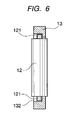
- Elongated holes 131 for accommodating the wedge members 12 are formed in the retainer 13 at eleven of twelve locations which are determined, for example, by dividing the circumference of the retainer 13 at predetermined intervals of 30 degrees.
- the elongated holes 131 extend parallel to the axis of the retainer 13.
- each wedge member 12 is movably held in the corresponding elongated hole 131 in such a manner that the wedge member 12 can be rotated about its axis.
- An engagement groove 132 is formed at either end of each elongated hole 131. Small-diameter boss portions 121 provided at opposite ends of each wedge member 12 are movably held in the corresponding engagement grooves 132, whereby the wedge member 12 is prevented from coming off toward the interior of the retainer 13.
- An engagement portion 133 to which the changeover mechanism 15 is coupled is formed at the remaining one location of the above-described twelve locations.
- the wedge guide grooves 14 are adapted to maintain the wedge members 12 in a free state in which the wedge members 12 move freely between the bottoms of the wedge guide grooves 14 and the outer circumferential surface of the fastening member 2 or to maintain the wedge members 12 in a caught state in which the wedge members 12 are caught between the bottoms of the wedge guide grooves 14 and the outer circumferential surface of the fastening member 2.
- the wedge guide grooves 14 are formed on the inner circumferential surface of the ring portion 111 to be arranged along the circumferential direction of the ring portion 111 at intervals corresponding to those of the wedge members 12.
- each of the wedge guide grooves 14 has a free region 141, and left-hand and right-hand wedge regions 142 and 143 which are provided on the opposite sides of the free region 141 and extend in the circumferential direction of the ring portion 111.
- the free region 141 maintains a wedge member 12 in a free state in which the wedge member 12 moves freely relative to the outer circumferential surface of the fastening member 2.
- Each of the left-hand and right-hand wedge regions 142 and 143 maintains the wedge member 12 in a caught state in which the wedge member 12 is caught by the outer circumferential surface of the fastening member 2.
- the changeover mechanism 15 is adapted to operate the retainer 13 in order to move each wedge member 12 to a position at which the wedge member 12 faces the free region 141 of the corresponding wedge guide groove 14, a position at which the wedge member 12 faces the left-hand wedge region 142 of the corresponding wedge guide groove 14, or a position at which the wedge member 12 faces the right-hand wedge region 143 of the corresponding wedge guide groove 14.
- the changeover mechanism 15 includes a changeover lever 152 which is mounted on the handle portion 112 at a position where the handle portion 112 merges into the ring portion 111, in such a manner that the lever can pivot horizontally.
- a first end portion 152a of the changeover lever 152 passes through the ring portion 111, and is coupled with the engagement portion 133 of the retainer 13.
- a positioning mechanism 16 is provided at a second end portion 152b of the changeover lever 152. The positioning mechanism 16 holds the changeover lever 152 at the selected one of three positions; i.e.
- the positioning mechanism 16 is composed of a click stop mechanism which includes a steel ball 162 movably accommodated in a blind hole 161 formed in the second end portion 152b of the changeover lever 152, the second end portion 152b facing the handle portion 112 of the wrench body 11; a spring member 163 accommodated in the blind hole 161 in order to urge the steel ball 162 toward the handle portion 112; and three engagement holes 164a to 164c which are formed on the surface of the handle portion 112 and with which the steel ball 162 selectively engages.
- the positions and intervals of the engagement holes 164a to 164c are determined to enable the changeover lever 15 to be positioned at the above-described three positions.
- the engagement hole 164a is used to position the retainer 13 at a neutral position N at which each wedge member 12 faces the corresponding free region 141; the engagement hole 164b is used to position the retainer 13 at a tightening position L at which each wedge member 12 faces the corresponding left-hand wedge region 142; and the engagement hole 164c is used to position the retainer 13 at a loosening position UL at which each wedge member 12 faces the corresponding right-hand wedge region 143.
- the changeover lever 152 of the changeover mechanism 15 is first rotated to the neutral position N in order to cause the steel ball 162 of the positioning mechanism 16 to engage the engagement hole 164a.
- each of the wedge members 12 held by the retainer 13 is caused to face the free region 141 of the corresponding wedge guide groove 14, as shown in Figure 7A, so that each of the wedge members 12 enters a free state.
- the changeover lever 152 of the changeover mechanism 15 may be rotated to the neutral position N after the wedge members 12 are released from the caught state. In this case, the operation of removing the wrench 10 from the fastening member 2 becomes easier.
- the changeover lever 152 of the changeover mechanism 15 is first rotated to the neutral position N in order to cause the steel ball 162 of the positioning mechanism 16 to engage the engagement hole 164a.
- each of the wedge members 12 held by the retainer 13 is caused to face the free region 141 of the corresponding wedge guide groove 14, so that each of the wedge members 12 enters a free state.
- the changeover lever 152 of the changeover mechanism 15 may be rotated to the neutral position N after the wedge members 12 are released from the caught state. In this case, the operation of removing the wrench 10 from the fastening member 2 becomes easier.
- the retainer 13 which holds the plurality of wedge members 12 arranged in the circumferential direction of the ring portion 111, is disposed inside the ring portion 111 to rotate along the inner circumferential surface of the ring portion 111;
- the wedge guide grooves 14 are formed on the inner circumferential surface of the ring portion 111 to be arranged at intervals corresponding to those of the wedge members 12, wherein each of the wedge guide grooves 14 has a free region 141 for maintaining a wedge member 12 in a free state in which the wedge member 12 moves freely relative to the outer circumferential surface of the fastening member 2, and left-hand and right-hand wedge regions 142 and 143, each maintaining the wedge member 12 in a caught state in which the wedge member 12 is caught by the outer circumferential surface of the fastening member 2;
- the changeover mechanism 15 for operating the retainer 13 is provided on the wrench body 11; and, by means of the changeover mechanism 15, the retainer 13 is moved to the position at which each wedge member 12 faces the free region
- each wedge member 12 can be positioned, in a reliable and stable manner, to the position at which the wedge member 12 faces the corresponding free region 141, the position at which the wedge member 12 faces the corresponding left-hand wedge region 142, or the position at which the wedge member 12 faces the corresponding right-hand wedge region 143.
- all the wedge members 12 can be simultaneously held in a free state or a caught state. Therefore, tightening and loosening of the fastening member 2 by use of the wrench 10 can be performed without any problem. Moreover, the work for tightening and loosening of the fastening member 2 can be facilitated, and thereby improving work efficiency.
- each wedge member 12 can be positioned, in a more reliable and stable manner, to the position at which the wedge member 12 faces the corresponding free region 141, the position at which the wedge member 12 faces the corresponding left-hand wedge region 142, or the position at which the wedge member 12 faces the corresponding right-hand wedge region 143.
- the changeover mechanism 15 has the changeover lever 152 connected to the retainer 13, all the wedge members 12 can be easily brought into the free state or the caught state through a simple operation of rotating the retainer 13 by use of the changeover lever 152.
- a wrench 20 shown in Figures 8 to 10 is adapted to be engaged with a cylindrical hole 2Aa of a fastening member 2A, such as a bolt having a cylindrical hole in its head portion, in order to tighten or loosen the fastening member 2A with respect to another member.
- the wrench 20 includes a wrench body 21, wedge members 22, a retainer 23, wedge guide grooves 24, and a changeover mechanism 25.
- the wrench body 21 has a handle portion 211, a cylindrical base portion 212 provided at one end of the handle portion 211, and a cylindrical body 213 concentrically provided on one end surface of the cylindrical base portion 212 and having a diameter smaller than that of the base portion 212.
- a fitting portion 214 for rotatably supporting one end of the retainer 23 is formed at a step portion between the base portion 212 and the cylindrical body 213.
- the wedge members 22 each assume a roller-like shape.
- each of the wedge members 22 is caught between the outer circumferential surface of the cylindrical body 213 and the inner circumference of the fastening member 2A to thereby couple the cylindrical body 213 and the fastening member 2A.
- the retainer 23 is adapted to hold the wedge members 22 at uniform intervals along the outer circumferential surface of the cylindrical body 213.
- the retainer 23 assumes a cylindrical, tubular shape, and has an inner diameter corresponding to the diameter of the cylindrical body 213 and an outer diameter corresponding to the diameter of the cylindrical hole 2Aa of the fastening member 2A.
- the retainer 23 has a wall thickness smaller than the diameter of the roller-shaped wedge members 22.
- Annular support portions 23a and 23b are formed at opposite ends, respectively, of the retainer 23, and are used to support the retainer 23 in such a manner that the retainer 23 rotates around the outer circumference of the cylindrical body 213.
- one annular support portion 23a is fitted into the fitting portion 214 of the base portion 212, and the other annular support portion 23b is fitted into a cap-shaped support member 28, which is fixed to a lower end of the cylindrical body 213 (as viewed in Figure 9) by use of a screw 27.
- the retainer 23 is supported in such a manner that the retainer 23 can rotate around the outer circumference of the cylindrical body 213.
- elongated holes 231 for accommodating the wedge members 22 are formed in the retainer 23 at eleven of twelve locations which are determined, for example, by dividing the circumference of the retainer 23 at predetermined intervals of 30 degrees.
- the elongated holes 231 extend parallel to the axis of the retainer 23.
- Each wedge member 22 is movably held in the corresponding elongated hole 231 in such a manner that the wedge member 22 can be rotated about its axis.
- the wedge members 22 are supported in such a manner that the wedge members 22 are prevented from coming off toward the exterior of the retainer 23.
- An engagement portion 233 to which the changeover mechanism 25 is coupled is formed at the one remaining location of the above-described twelve locations.
- the wedge guide grooves 24 are adapted to maintain the wedge members 22 in a free state in which the wedge members 22 move freely between the bottoms of the wedge guide grooves 24 and the inner circumferential surface of the cylindrical hole 2Aa of the fastening member 2A and to maintain the wedge members 22 in a caught state in which the wedge members 22 are caught between the bottoms of the wedge guide grooves 24 and the inner circumferential surface of the cylindrical hole 2Aa of the fastening member 2A.
- the wedge guide grooves 24 are formed on the outer circumferential surface of the cylindrical body 213 to be arranged along the circumferential direction of the cylindrical body 213 at intervals corresponding to those of the wedge members 22.
- each of the wedge guide grooves 24 has a free region 241, and left-hand and right-hand wedge regions 242 and 243 which are provided on the opposite sides of the free region 241 and extend in the circumferential direction of the cylindrical body 213.
- the free region 241 maintains a wedge member 22 in a free state in which the wedge member 22 moves freely relative to the inner circumferential surface of the cylindrical hole 2Aa of the fastening member 2A.
- Each of the left-hand and right-hand wedge regions 242 and 243 maintains the wedge member 22 in a caught state in which the wedge member 22 is caught by the inner circumferential surface of the cylindrical hole 2Aa of the fastening member 2A.
- the changeover mechanism 25 is adapted to operate the retainer 23 in order to move each wedge member 22 to a position at which the wedge member 22 faces the free region 241 of the corresponding wedge guide groove 24, a position at which the wedge member 22 faces the left-hand wedge region 242 of the corresponding wedge guide groove 24, or a position at which the wedge member 22 faces the right-hand wedge region 243 of the corresponding wedge guide groove 24.
- the changeover mechanism 25 includes a changeover lever 252 which is mounted on the handle portion 211 at a position where the handle portion 211 merges into the base portion 212, in such a manner that the changeover lever 252 can pivot horizontally.
- a first end portion 252a of the changeover lever 252 is coupled with the engagement portion 233 of the retainer 23.
- a positioning mechanism 26 is provided at a second end portion 252b of the changeover lever 252. The positioning mechanism 26 holds the changeover lever 252 at the selected one of three positions; i.e.
- the positioning mechanism 26 is composed of a click stop mechanism which includes a steel ball 262 movably accommodated in a blind hole 261 formed in the second end portion 252b of the changeover lever 252, the second end portion 252b facing the handle portion 211 of the wrench body 21; a spring member 263 accommodated in the blind hole 261 in order to urge the steel ball 262 toward the handle portion 211; and three engagement holes 264a to 264c which are formed on the surface of the handle portion 211 and with which the steel ball 262 selectively engages. The positions and intervals of the engagement holes 264a to 264c are determined to enable the changeover lever 25 to be positioned at the above-described three positions.
- the engagement hole 264a is used to position the retainer 23 at a neutral position N at which each wedge member 22 faces the corresponding free region 241;
- the engagement hole 264b is used to position the retainer 23 at a tightening position L at which each wedge member 22 faces the corresponding left-hand wedge region 242;
- the engagement hole 264c is used to position the retainer 23 at a loosening position UL at which each wedge member 22 faces the corresponding right-hand wedge region 243.
- the changeover lever 252 of the changeover mechanism 25 is first rotated to the neutral position N in order to cause the steel ball 262 of the positioning mechanism 26 to engage the engagement hole 264a.
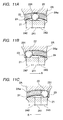
- each of the wedge members 22 held by the retainer 23 is caused to face the free region 241 of the corresponding wedge guide groove 24, as shown in Figure 11A, so that each of the wedge members 22 enters a free state.
- the wrench body 21 is rotated slightly in the direction opposite the direction of arrow A of Figure 11B in order to release each wedge member 22 from the caught state established between the wall surface of the left-hand wedge region 242 and the inner circumferential surface of the cylindrical hole 2Aa of the fastening member 2A.
- the wrench 20 can be easily removed from the fastening member 2A.
- the changeover lever 252 of the changeover mechanism 25 may be rotated to the neutral position N after the wedge members 22 are released from the caught state. In this case, the operation of removing the wrench 20 from the fastening member 2A becomes easier.
- the changeover lever 252 of the changeover mechanism 25 is first rotated to the neutral position N in order to cause the steel ball 262 of the positioning mechanism 26 to engage the engagement hole 264a.
- each of the wedge members 22 held by the retainer 23 is caused to face the free region 241 of the corresponding wedge guide groove 24, whereby each of the wedge members 22 enters a free state.
- the wrench body 21 is rotated slightly in the direction opposite the direction of arrow B of Figure 11C in order to release each wedge member 22 from the caught state established between the wall surface of the right-hand wedge region 243 and the inner circumferential surface of the cylindrical hole 2Aa of the fastening member 2A.
- the wrench 20 can be easily removed from the fastening member 2A.
- the changeover lever 252 of the changeover mechanism 25 may be rotated to the neutral position N after the wedge members 22 are released from the caught state. In this case, the operation of removing the wrench 20 from the fastening member 2A becomes easier.
- the retainer 23 which holds the plurality of wedge members 22 arranged in the circumferential direction of the cylindrical body 213, is disposed outside the cylindrical body 213 to rotate around the outer circumferential surface of the cylindrical body 213;
- the wedge guide grooves 24 are formed on the outer circumferential surface of the cylindrical body 213 to be arranged at intervals corresponding to those of the wedge members 22, wherein each of the wedge guide grooves 24 has a free region 241 for maintaining a wedge member 22 in a free state in which the wedge member 22 moves freely relative to the inner circumferential surface of the cylindrical hole 2Aa of the fastening member 2A, and left-hand and right-hand wedge regions 242 and 243, each maintaining the wedge member 22 in a caught state in which the wedge member 22 is caught by the inner circumferential surface of the cylindrical hole 2Aa of the fastening member 2A;
- the changeover mechanism 25 for operating the retainer 23 is provided on the wrench body 21; and, by means of the changeover mechanism 25, the retainer 23 is moved to the
- each wedge member 22 can be positioned, in a reliable and stable manner, to the position at which the wedge member 22 faces the corresponding free region 241, the position at which the wedge member 22 faces the corresponding left-hand wedge region 242, or the position at which the wedge member 22 faces the corresponding right-hand wedge region 243.
- all the wedge members 22 can be simultaneously held in a free state or a caught state. Therefore, tightening and loosening of the fastening member 2A having the cylindrical hole 2Aa by use of the wrench 20 can be performed without any problem. Moreover, the work for tightening and loosening of the fastening member 2A can be facilitated, thereby improving work efficiency.
- each wedge member 22 can be positioned, in a more reliable and stable manner, to the position at which the wedge member 22 faces the corresponding free region 241, the position at which the wedge member 22 faces the corresponding left-hand wedge region 242, or the position at which the wedge member 22 faces the corresponding right-hand wedge region 243.
- the changeover mechanism 25 has the changeover lever 252 connected to the retainer 23, all the wedge members 22 can be easily brought into the free state or the caught state through a simple operation of rotating the retainer 23 by use of the changeover lever 252.
- each wedge member 12 (22) may be positioned to the position at which the wedge member 12 (22) faces the corresponding free region 141 (241), the position at which the wedge member 12 (22) faces the corresponding left-hand wedge region 142 (242), or the position at which the wedge member 12 (22) faces the corresponding right-hand wedge region 143 (243).
- the positioning mechanisms 16 and 26 of the changeover mechanisms 15 and 25 of the above-described embodiments may be omitted.
- the wedge guide grooves 14 of the ring portion 111 and the wedge guide grooves 24 of the cylindrical body 213 are each composed of the free region 141 or 241, the left-hand wedge region 142 or 242, and the right-hand wedge region 143 or 243.
- the present invention is not limited thereto and, for example, each of the wedge guide grooves 14 or 24 may be composed of a free region and a single wedge region on the left-hand or right-hand side.
- the illustrated embodiments of the present invention provide a wrench for tightening or loosening a fastening member with respect to another member, which wrench has a changeover mechanism for moving each wedge member between a free region and a wedge region, and enables reliable and stable positioning of each wedge member at a position in which the wedge member faces the free region or a position in which the wedge member faces the wedge region, whereby all the wedge members are simultaneously and stably held in a free state or a caught state. Accordingly, tightening and loosening of a fastening member by use of the wrench can be performed without any problem. Moreover, the work for tightening and loosening of the fastening member can be facilitated, thereby improving work efficiency.
- each wedge member can be positioned, in a more reliable and stable manner, at a position in which the wedge member faces the free region or a position in which the wedge member faces the wedge region.
- the changeover mechanism includes a changeover lever connected to the retainer, all the wedge members can be easily brought into a free state or a caught state through mere operation of the retainer by use of the changeover lever.
Landscapes
- Engineering & Computer Science (AREA)
- Mechanical Engineering (AREA)
- Details Of Spanners, Wrenches, And Screw Drivers And Accessories (AREA)
Applications Claiming Priority (2)
| Application Number | Priority Date | Filing Date | Title |
|---|---|---|---|
| JP2002199882 | 2002-07-09 | ||
| JP2002199882A JP4157334B2 (ja) | 2002-07-09 | 2002-07-09 | スパナ |
Publications (2)
| Publication Number | Publication Date |
|---|---|
| EP1380390A2 true EP1380390A2 (de) | 2004-01-14 |
| EP1380390A3 EP1380390A3 (de) | 2008-11-05 |
Family
ID=29728437
Family Applications (1)
| Application Number | Title | Priority Date | Filing Date |
|---|---|---|---|
| EP03102068A Withdrawn EP1380390A3 (de) | 2002-07-09 | 2003-07-09 | Ratschenschlüssel |
Country Status (5)
| Country | Link |
|---|---|
| US (2) | US7181998B2 (de) |
| EP (1) | EP1380390A3 (de) |
| JP (1) | JP4157334B2 (de) |
| KR (1) | KR100703144B1 (de) |
| TW (1) | TW555625B (de) |
Cited By (4)
| Publication number | Priority date | Publication date | Assignee | Title |
|---|---|---|---|---|
| TWI448364B (de) * | 2012-06-06 | 2014-08-11 | ||
| EP3168006A4 (de) * | 2014-07-11 | 2018-04-18 | Hangzhou Great Star Tools Co., Ltd. | Stiller schraubenschlüssel |
| DE102022113887A1 (de) | 2022-06-01 | 2023-12-07 | Wiha Werkzeuge Gmbh | Isoliertes Drehwerkzeug |
| DE102023126030A1 (de) | 2023-09-26 | 2025-03-27 | Wiha Werkzeuge Gmbh | Isoliertes Drehwerkzeug |
Families Citing this family (23)
| Publication number | Priority date | Publication date | Assignee | Title |
|---|---|---|---|---|
| US20020144575A1 (en) * | 1999-09-17 | 2002-10-10 | David Niven | Gripping or clamping mechanisms |
| US7213492B2 (en) * | 2004-10-29 | 2007-05-08 | Chen-Chang Tsai | Control mechanism for a socket wrench |
| US20060288822A1 (en) * | 2005-06-22 | 2006-12-28 | Peter Langas | Ratchet wrench |
| US20070151423A1 (en) * | 2005-12-30 | 2007-07-05 | Proxene Tools Co., Ltd. | Apparatus of reverse ratchet wrench to indicate the driving orientation |
| TW201000269A (en) * | 2008-06-27 | 2010-01-01 | Hou-Fei Hu | Three-way type button wrench |
| JP2010158741A (ja) * | 2009-01-08 | 2010-07-22 | Tanaka Kinzoku:Kk | レンチ及びレンチ用螺着部材 |
| JP5404105B2 (ja) * | 2009-03-09 | 2014-01-29 | 株式会社日研工作所 | クランプ機構、およびこのクランプ機構を備えるスパナおよびツールクランパ |
| US7975573B2 (en) * | 2009-04-03 | 2011-07-12 | Gummow Stephen A | Hand tool with stepless locking mechanism |
| JP5416572B2 (ja) * | 2009-12-24 | 2014-02-12 | 株式会社アルプスツール | スパナ |
| MX2010002057A (es) * | 2010-02-22 | 2011-08-31 | Luis Gerardo Oyervides Ochoa | Llave de rodillos auto-ajustables. |
| TWI379739B (en) | 2010-12-06 | 2012-12-21 | Jyun Wun Liao | Sleeve structure for a spanner |
| US10125555B2 (en) * | 2013-05-02 | 2018-11-13 | Weatherford Technology Holdings, Llc | Tubular handling tool |
| CN104314947A (zh) * | 2014-10-30 | 2015-01-28 | 南京信息职业技术学院 | 一种防盗螺母及扳手 |
| US11110570B2 (en) * | 2015-01-06 | 2021-09-07 | Earl Stuart Douglass | Reversible roller wrench with a scalloped outer race |
| JP5914715B1 (ja) * | 2015-02-19 | 2016-05-11 | 株式会社日研工作所 | フックスパナ |
| CN107614203A (zh) * | 2015-03-16 | 2018-01-19 | 凯文·戴恩 | 可逆扳手 |
| KR101685382B1 (ko) | 2015-12-09 | 2016-12-28 | 한국항공우주연구원 | 개방형 기어 스패너 |
| CN106737340B (zh) * | 2016-11-23 | 2018-10-26 | 浙江力源工具有限公司 | 一种摩擦式棘轮扳手 |
| US11235441B2 (en) | 2019-02-06 | 2022-02-01 | Albertson Enterprises, Llc | Wrench |
| US10668600B1 (en) | 2019-02-06 | 2020-06-02 | Jingrong Ye | Wrench |
| US11161222B2 (en) | 2019-02-06 | 2021-11-02 | Weikai Yang | Wrench |
| TWI789690B (zh) * | 2020-02-25 | 2023-01-11 | 優鋼機械股份有限公司 | 滾子扳手 |
| CN112828814A (zh) * | 2021-02-07 | 2021-05-25 | 泰州星瑞精密工业有限公司 | 一种用于紧固圆柱形螺杆的快速拧紧专用工具 |
Citations (1)
| Publication number | Priority date | Publication date | Assignee | Title |
|---|---|---|---|---|
| WO2001021933A1 (en) | 1999-09-17 | 2001-03-29 | Austoil Engineering Services Ltd | Clamping mechanism, clutch and apparatus incorporating the same |
Family Cites Families (14)
| Publication number | Priority date | Publication date | Assignee | Title |
|---|---|---|---|---|
| US592213A (en) * | 1897-10-19 | Hand drilling-iviachine | ||
| US1412688A (en) * | 1920-10-21 | 1922-04-11 | James L Layton | Tool holder |
| DE8900543U1 (de) * | 1989-01-19 | 1989-02-23 | Chern, Shyh Yueh, Tali Hsiang, Taichung | Schlüssel zum Anziehen und Lösen von Schrauben und Muttern |
| JP3155888B2 (ja) | 1993-07-08 | 2001-04-16 | 大昭和精機株式会社 | スパナ |
| US6276239B1 (en) * | 1995-06-07 | 2001-08-21 | David V. Albertson | Hand tool |
| GB2318535A (en) * | 1996-10-22 | 1998-04-29 | Frank Mccann | Ratchet wrench |
| US5941140A (en) * | 1996-10-31 | 1999-08-24 | Alvin C. Collins | Reversible stepless wrench |
| US5848561A (en) * | 1996-11-06 | 1998-12-15 | Hsieh; Chih-Ching | Ratchet socket wrench and socket arrangement |
| KR19990019947A (ko) * | 1997-08-30 | 1999-03-25 | 양재신 | 볼트 및 너트 체결용 공구 |
| US6112624A (en) * | 1998-10-01 | 2000-09-05 | Chen; Yu-Tzu | Rotary lever assembly for a wrench with a direction control mechanism |
| US6202513B1 (en) * | 1999-12-23 | 2001-03-20 | Ching-Chih Pan | Socket wrench |
| US6253646B1 (en) * | 2000-03-09 | 2001-07-03 | Chuck (Chen-Tsai) Chang | Roller-type ratchet device for wrench |
| JP4187905B2 (ja) * | 2000-05-11 | 2008-11-26 | Ntn株式会社 | クラッチユニット |
| KR100373421B1 (ko) * | 2000-06-23 | 2003-03-04 | 하태환 | 렌치 |
-
2002
- 2002-07-09 JP JP2002199882A patent/JP4157334B2/ja not_active Expired - Lifetime
-
2003
- 2003-02-20 TW TW092103529A patent/TW555625B/zh not_active IP Right Cessation
- 2003-03-03 KR KR1020030013060A patent/KR100703144B1/ko not_active Expired - Lifetime
- 2003-07-08 US US10/616,285 patent/US7181998B2/en not_active Expired - Lifetime
- 2003-07-09 EP EP03102068A patent/EP1380390A3/de not_active Withdrawn
-
2005
- 2005-05-05 US US11/123,991 patent/US7036400B2/en not_active Expired - Lifetime
Patent Citations (1)
| Publication number | Priority date | Publication date | Assignee | Title |
|---|---|---|---|---|
| WO2001021933A1 (en) | 1999-09-17 | 2001-03-29 | Austoil Engineering Services Ltd | Clamping mechanism, clutch and apparatus incorporating the same |
Cited By (6)
| Publication number | Priority date | Publication date | Assignee | Title |
|---|---|---|---|---|
| TWI448364B (de) * | 2012-06-06 | 2014-08-11 | ||
| EP3168006A4 (de) * | 2014-07-11 | 2018-04-18 | Hangzhou Great Star Tools Co., Ltd. | Stiller schraubenschlüssel |
| US10335928B2 (en) | 2014-07-11 | 2019-07-02 | Hangzhou Great Star Tools Co., Ltd. | Quiet wrench |
| DE102022113887A1 (de) | 2022-06-01 | 2023-12-07 | Wiha Werkzeuge Gmbh | Isoliertes Drehwerkzeug |
| DE102022113887B4 (de) | 2022-06-01 | 2024-04-25 | Wiha Werkzeuge Gmbh | Isoliertes Drehwerkzeug |
| DE102023126030A1 (de) | 2023-09-26 | 2025-03-27 | Wiha Werkzeuge Gmbh | Isoliertes Drehwerkzeug |
Also Published As
| Publication number | Publication date |
|---|---|
| JP4157334B2 (ja) | 2008-10-01 |
| US20050199101A1 (en) | 2005-09-15 |
| JP2004042156A (ja) | 2004-02-12 |
| EP1380390A3 (de) | 2008-11-05 |
| TW555625B (en) | 2003-10-01 |
| KR100703144B1 (ko) | 2007-04-05 |
| KR20040005572A (ko) | 2004-01-16 |
| TW200400868A (en) | 2004-01-16 |
| US7036400B2 (en) | 2006-05-02 |
| US20040007097A1 (en) | 2004-01-15 |
| US7181998B2 (en) | 2007-02-27 |
Similar Documents
| Publication | Publication Date | Title |
|---|---|---|
| EP1380390A2 (de) | Ratschenschlüssel | |
| US5407215A (en) | Chuck assembly for holding releasably a bit member | |
| KR950005121B1 (ko) | 조정 가능한 래칫 렌치 | |
| US6112624A (en) | Rotary lever assembly for a wrench with a direction control mechanism | |
| EP0924038B1 (de) | Werkzeugeinspannvorrichtung für eine Oberfräse | |
| US8328475B2 (en) | Cutting tool assembly including a release mechanism | |
| US7373861B2 (en) | Pivoting assembly of a hand tool | |
| US8079294B2 (en) | Support leg devices and cutting tools having the support leg devices | |
| US6224304B1 (en) | Bit attaching arrangement for power tool | |
| JPH09109065A (ja) | 電動工具用補助ハンドル | |
| US20060090609A1 (en) | Ratchet wrench | |
| US6591718B1 (en) | Ratchet wrench | |
| US10875102B2 (en) | Hybrid holding device | |
| US7146882B1 (en) | Ratchet wrench | |
| JP2001105333A (ja) | 作業工具用ソケット | |
| JP3155888B2 (ja) | スパナ | |
| JP4268840B2 (ja) | 取外工具 | |
| JPH091260A (ja) | 迅速金型交換装置 | |
| JP2601016Y2 (ja) | ラチェットレンチ及び締付工具 | |
| US20260084270A1 (en) | Ratchet wrench assembly structure | |
| JP2004345011A (ja) | ラチェットレンチ | |
| JP4456841B2 (ja) | レンチ | |
| JP3043106U (ja) | 作業工具 | |
| JPH06226649A (ja) | レンチ工具 | |
| KR20160118659A (ko) | 래칫 렌치용 소켓 |
Legal Events
| Date | Code | Title | Description |
|---|---|---|---|
| PUAI | Public reference made under article 153(3) epc to a published international application that has entered the european phase |
Free format text: ORIGINAL CODE: 0009012 |
|
| AK | Designated contracting states |
Kind code of ref document: A2 Designated state(s): AT BE BG CH CY CZ DE DK EE ES FI FR GB GR HU IE IT LI LU MC NL PT RO SE SI SK TR |
|
| AX | Request for extension of the european patent |
Extension state: AL LT LV MK |
|
| RIN1 | Information on inventor provided before grant (corrected) |
Inventor name: MIKADO, SUSUMU Inventor name: TAGUCHI, MASAHIRO Inventor name: MATSUMOTO, MASAKAZU |
|
| PUAL | Search report despatched |
Free format text: ORIGINAL CODE: 0009013 |
|
| AK | Designated contracting states |
Kind code of ref document: A3 Designated state(s): AT BE BG CH CY CZ DE DK EE ES FI FR GB GR HU IE IT LI LU MC NL PT RO SE SI SK TR |
|
| AX | Request for extension of the european patent |
Extension state: AL LT LV MK |
|
| 17P | Request for examination filed |
Effective date: 20090506 |
|
| AKX | Designation fees paid |
Designated state(s): AT BE BG CH CY CZ DE DK EE ES FI FR GB GR HU IE IT LI LU MC NL PT RO SE SI SK TR |
|
| 17Q | First examination report despatched |
Effective date: 20101011 |
|
| STAA | Information on the status of an ep patent application or granted ep patent |
Free format text: STATUS: THE APPLICATION IS DEEMED TO BE WITHDRAWN |
|
| 18D | Application deemed to be withdrawn |
Effective date: 20140718 |