EP1380537A1 - Dispositif de production d'un mélange eau-ozone et dispositif de production de mélanges gaz-liquide - Google Patents
Dispositif de production d'un mélange eau-ozone et dispositif de production de mélanges gaz-liquide Download PDFInfo
- Publication number
- EP1380537A1 EP1380537A1 EP02254788A EP02254788A EP1380537A1 EP 1380537 A1 EP1380537 A1 EP 1380537A1 EP 02254788 A EP02254788 A EP 02254788A EP 02254788 A EP02254788 A EP 02254788A EP 1380537 A1 EP1380537 A1 EP 1380537A1
- Authority
- EP
- European Patent Office
- Prior art keywords
- gas
- water
- ozone
- vessel
- conduit
- Prior art date
- Legal status (The legal status is an assumption and is not a legal conclusion. Google has not performed a legal analysis and makes no representation as to the accuracy of the status listed.)
- Withdrawn
Links
- CBENFWSGALASAD-UHFFFAOYSA-N Ozone Chemical compound [O-][O+]=O CBENFWSGALASAD-UHFFFAOYSA-N 0.000 title claims abstract description 176
- XLYOFNOQVPJJNP-UHFFFAOYSA-N water Substances O XLYOFNOQVPJJNP-UHFFFAOYSA-N 0.000 title claims abstract description 131
- 239000007788 liquid Substances 0.000 title claims abstract description 64
- 239000000203 mixture Substances 0.000 title claims 2
- 239000003054 catalyst Substances 0.000 claims abstract description 15
- 238000005868 electrolysis reaction Methods 0.000 claims description 20
- 239000000463 material Substances 0.000 claims description 16
- 230000001105 regulatory effect Effects 0.000 claims 3
- 239000007789 gas Substances 0.000 description 53
- 238000007599 discharging Methods 0.000 description 41
- 230000007246 mechanism Effects 0.000 description 11
- 238000000034 method Methods 0.000 description 9
- 238000010586 diagram Methods 0.000 description 8
- 238000004140 cleaning Methods 0.000 description 6
- 230000001954 sterilising effect Effects 0.000 description 4
- QVGXLLKOCUKJST-UHFFFAOYSA-N atomic oxygen Chemical compound [O] QVGXLLKOCUKJST-UHFFFAOYSA-N 0.000 description 3
- 238000005259 measurement Methods 0.000 description 3
- 239000001301 oxygen Substances 0.000 description 3
- 229910052760 oxygen Inorganic materials 0.000 description 3
- 238000005406 washing Methods 0.000 description 3
- 238000005452 bending Methods 0.000 description 2
- 238000010276 construction Methods 0.000 description 2
- YADSGOSSYOOKMP-UHFFFAOYSA-N dioxolead Chemical compound O=[Pb]=O YADSGOSSYOOKMP-UHFFFAOYSA-N 0.000 description 2
- 238000004880 explosion Methods 0.000 description 2
- GPRLSGONYQIRFK-UHFFFAOYSA-N hydron Chemical group [H+] GPRLSGONYQIRFK-UHFFFAOYSA-N 0.000 description 2
- 238000004519 manufacturing process Methods 0.000 description 2
- 230000003068 static effect Effects 0.000 description 2
- MYMOFIZGZYHOMD-UHFFFAOYSA-N Dioxygen Chemical compound O=O MYMOFIZGZYHOMD-UHFFFAOYSA-N 0.000 description 1
- UFHFLCQGNIYNRP-UHFFFAOYSA-N Hydrogen Chemical compound [H][H] UFHFLCQGNIYNRP-UHFFFAOYSA-N 0.000 description 1
- 238000004332 deodorization Methods 0.000 description 1
- 238000007865 diluting Methods 0.000 description 1
- 229910001882 dioxygen Inorganic materials 0.000 description 1
- 238000009826 distribution Methods 0.000 description 1
- 238000011156 evaluation Methods 0.000 description 1
- 235000013305 food Nutrition 0.000 description 1
- 239000001257 hydrogen Substances 0.000 description 1
- 229910052739 hydrogen Inorganic materials 0.000 description 1
- 239000003014 ion exchange membrane Substances 0.000 description 1
- 239000012528 membrane Substances 0.000 description 1
- 230000003647 oxidation Effects 0.000 description 1
- 238000007254 oxidation reaction Methods 0.000 description 1
- 230000000737 periodic effect Effects 0.000 description 1
- 230000010349 pulsation Effects 0.000 description 1
- 238000004659 sterilization and disinfection Methods 0.000 description 1
- 239000000126 substance Substances 0.000 description 1
- 230000000153 supplemental effect Effects 0.000 description 1
- 239000008399 tap water Substances 0.000 description 1
- 235000020679 tap water Nutrition 0.000 description 1
- 229910021642 ultra pure water Inorganic materials 0.000 description 1
- 239000012498 ultrapure water Substances 0.000 description 1
- 235000013311 vegetables Nutrition 0.000 description 1
Images




Classifications
-
- C—CHEMISTRY; METALLURGY
- C01—INORGANIC CHEMISTRY
- C01B—NON-METALLIC ELEMENTS; COMPOUNDS THEREOF; METALLOIDS OR COMPOUNDS THEREOF NOT COVERED BY SUBCLASS C01C
- C01B13/00—Oxygen; Ozone; Oxides or hydroxides in general
- C01B13/10—Preparation of ozone
-
- B—PERFORMING OPERATIONS; TRANSPORTING
- B01—PHYSICAL OR CHEMICAL PROCESSES OR APPARATUS IN GENERAL
- B01F—MIXING, e.g. DISSOLVING, EMULSIFYING OR DISPERSING
- B01F23/00—Mixing according to the phases to be mixed, e.g. dispersing or emulsifying
- B01F23/20—Mixing gases with liquids
- B01F23/23—Mixing gases with liquids by introducing gases into liquid media, e.g. for producing aerated liquids
- B01F23/232—Mixing gases with liquids by introducing gases into liquid media, e.g. for producing aerated liquids using flow-mixing means for introducing the gases, e.g. baffles
- B01F23/2323—Mixing gases with liquids by introducing gases into liquid media, e.g. for producing aerated liquids using flow-mixing means for introducing the gases, e.g. baffles by circulating the flow in guiding constructions or conduits
- B01F23/23231—Mixing gases with liquids by introducing gases into liquid media, e.g. for producing aerated liquids using flow-mixing means for introducing the gases, e.g. baffles by circulating the flow in guiding constructions or conduits being at least partially immersed in the liquid, e.g. in a closed circuit
-
- B—PERFORMING OPERATIONS; TRANSPORTING
- B01—PHYSICAL OR CHEMICAL PROCESSES OR APPARATUS IN GENERAL
- B01F—MIXING, e.g. DISSOLVING, EMULSIFYING OR DISPERSING
- B01F23/00—Mixing according to the phases to be mixed, e.g. dispersing or emulsifying
- B01F23/20—Mixing gases with liquids
- B01F23/23—Mixing gases with liquids by introducing gases into liquid media, e.g. for producing aerated liquids
- B01F23/2366—Parts; Accessories
- B01F23/2368—Mixing receptacles, e.g. tanks, vessels or reactors, being completely closed, e.g. hermetically closed
-
- B—PERFORMING OPERATIONS; TRANSPORTING
- B01—PHYSICAL OR CHEMICAL PROCESSES OR APPARATUS IN GENERAL
- B01F—MIXING, e.g. DISSOLVING, EMULSIFYING OR DISPERSING
- B01F35/00—Accessories for mixers; Auxiliary operations or auxiliary devices; Parts or details of general application
- B01F35/20—Measuring; Control or regulation
- B01F35/21—Measuring
- B01F35/211—Measuring of the operational parameters
- B01F35/2112—Level of material in a container or the position or shape of the upper surface of the material
-
- B—PERFORMING OPERATIONS; TRANSPORTING
- B01—PHYSICAL OR CHEMICAL PROCESSES OR APPARATUS IN GENERAL
- B01F—MIXING, e.g. DISSOLVING, EMULSIFYING OR DISPERSING
- B01F25/00—Flow mixers; Mixers for falling materials, e.g. solid particles
- B01F2025/91—Direction of flow or arrangement of feed and discharge openings
- B01F2025/915—Reverse flow, i.e. flow changing substantially 180° in direction
-
- B—PERFORMING OPERATIONS; TRANSPORTING
- B01—PHYSICAL OR CHEMICAL PROCESSES OR APPARATUS IN GENERAL
- B01F—MIXING, e.g. DISSOLVING, EMULSIFYING OR DISPERSING
- B01F23/00—Mixing according to the phases to be mixed, e.g. dispersing or emulsifying
- B01F23/20—Mixing gases with liquids
- B01F23/23—Mixing gases with liquids by introducing gases into liquid media, e.g. for producing aerated liquids
- B01F23/237—Mixing gases with liquids by introducing gases into liquid media, e.g. for producing aerated liquids characterised by the physical or chemical properties of gases or vapours introduced in the liquid media
- B01F23/2376—Mixing gases with liquids by introducing gases into liquid media, e.g. for producing aerated liquids characterised by the physical or chemical properties of gases or vapours introduced in the liquid media characterised by the gas being introduced
- B01F23/23761—Aerating, i.e. introducing oxygen containing gas in liquids
- B01F23/237613—Ozone
-
- C—CHEMISTRY; METALLURGY
- C02—TREATMENT OF WATER, WASTE WATER, SEWAGE, OR SLUDGE
- C02F—TREATMENT OF WATER, WASTE WATER, SEWAGE, OR SLUDGE
- C02F2201/00—Apparatus for treatment of water, waste water or sewage
- C02F2201/78—Details relating to ozone treatment devices
- C02F2201/784—Diffusers or nozzles for ozonation
-
- C—CHEMISTRY; METALLURGY
- C02—TREATMENT OF WATER, WASTE WATER, SEWAGE, OR SLUDGE
- C02F—TREATMENT OF WATER, WASTE WATER, SEWAGE, OR SLUDGE
- C02F2303/00—Specific treatment goals
- C02F2303/04—Disinfection
Definitions
- the present invention relates to an ozone water producing apparatus for generating ozone water having a predetermined concentration by dissolving appropriately generated ozone gas into water, and particularly, relates to an improved technique for obtaining ozone water having a predetermined concentration with a simple mechanism.
- Ozone has strong oxidation power and sterilizing power, and is used such as for deodorization and/or sterilization.
- an ozone water producing apparatus which is used such as in medical facilities.
- An ozone water producing apparatus generates ozone gas with an appropriate method, such as electrical discharging or electrolysis, and produces ozone water by dissolving the ozone gas into water.
- the ozone water produced by such apparatuses is used as cleansing water for hand-washing.
- Ozone water must be accurately prepared to have a suitable concentration so that upon usage, it has an effective sterilizing power while being harmless to the human body.
- Ozone water producing apparatus in order for an ozone water producing apparatus to obtain manufacturing approval for use as a medical device, it is necessary for the apparatus to be able to control the concentration of ozone water within the precision of 4 ⁇ 0.5 ppm in weight ratio.
- hand-washing for 30 seconds with ozone water having a concentration of 4 ppm is most effective in terms of both sterilizing efficiency and safety.
- ozone is an extremely instable substance, it has been difficult to supply ozone water of constant concentration with a good accuracy.
- the apparatus In the formerly-devised ozone water producing apparatus, a method is adopted in which a high-concentration ozone water controlled with high precision is stored, and ozone water with a desired concentration is obtained by diluting the stored high-concentration ozone water upon hand-washing. Therefore, the apparatus is suitable for usage wherein ozone water having a constant concentration is intermittently used.
- ozone water having a predetermined concentration is continuously used for a long period of time.
- An example thereof is industrial cleansing usage and/or the usage for cleansing foods such as vegetables.
- the above-mentioned ozone water producing apparatus for medical use may not be optimal.
- the medical-usage ozone water producing apparatus is for the usage in the medical field, not only is it necessary for the apparatus to fulfill the approval requirements as a medical device, but also, the apparatus is actually required to control the concentration of ozone water much strictly than the concentration-control range defined in the above-mentioned requirements. Therefore, a medical-usage ozone water producing apparatus is subjected to a too strict specification to be applied for industrial usages, and it may be said that widespread usage of cleaning with ozone water for industrial purposes would be too expensive.
- the present invention has been contrived in view of the above and other matters, and one object of the present invention is to provide a safe and inexpensive ozone water producing apparatus which can continuously supply ozone water having an effective concentration for a long period of time.
- an ozone water producing apparatus comprises: a gas-liquid mixing vessel with a closed structure having a water-discharging port near the bottom thereof and a gas-discharging port at an upper portion thereof; an inner vessel provided inside the gas-liquid mixing vessel, the inner vessel having an upper opening positioned lower than the gas-discharging port of the gas-liquid mixing vessel; a main conduit having one end extending into the gas-liquid mixing vessel and opening at a lower portion inside the inner vessel, and having an other end connected to a pressure source of material water via a water-supplying valve; a gas-induction conduit having one end connecting to a point along the main conduit, and having an other end connected to an outlet of a gas-induction valve; a gas-discharging conduit having one end connected to the gas-discharging port of the gas-liquid mixing vessel, and having an other end connected to an inlet of a gas-discharging valve; a communicating conduit connecting an inlet of the gas-induction valve and an outlet of the gas-disc
- Fig. 1 shows a schematic construction diagram of an ozone water producing apparatus according to one example of the present invention.
- the ozone water producing apparatus generally comprises an ozone-generating section 20, a gas-liquid mixing section 30, and a water-cleaning section 10.
- the ozone-generating section 20 generates ozone with an electrolysis cell using an electrolysis ozone generating method.
- an electrolysis cell has a structure in which an anode 21 carries an ozone-generating catalyst such as lead dioxide, and a hydrogen-ion exchange membrane (PEM, proton exchange membrane) 23 is sandwiched between the anode 21 and a cathode 22.
- PEM hydrogen-ion exchange membrane
- Pure water is introduced to the anode 21 and a current is passed between the electrodes 21, 22 to cause electrolysis of water.
- a portion of oxygen having been generated upon electrolysis turns into ozone by the ozone-generating catalyst, and a mixed gas (ozone-containing gas) comprising ozone and oxygen is generated from the anode 21.
- Hydrogen ion generated upon electrolysis reaches the cathode 22 through the PEM 23, obtains an electron, and turns into hydrogen.
- the ozone-containing gas generated at the ozone-generating section 20 is introduced to the gas-liquid mixing section 30.
- the ozone gas is dissolved into water, and ozone water is produced and discharged.
- the water-cleaning section 10 comprises various types of filters, and produces water adjusted to have various levels of purity, such as ultrapure water to be electrolyzed at the electrolysis cell and/or material water for dissolving ozone gas, using raw water such as tap water.
- Fig. 2 shows a schematic structural diagram of the gas-liquid mixing section 30.
- the gas-liquid mixing section 30 mainly comprises a gas-liquid mixing vessel 31 with a closed structure.
- An inner vessel 33 having an opening 40 at an upper position (at the top in this example) is defined and formed inside the gas-liquid mixing vessel 31.
- the gas-liquid mixing section 30 further comprises: an aspirator 34 which introduces and mixes the ozone-containing oxygen gas and the material water and which emits the mixed gas and liquid into the inner vessel 33; a water-discharging conduit 54 for discharging ozone water from the gas-liquid mixing vessel 31; a gas-discharging conduit 52 for discharging outside the undissolved ozone gas within the gas-liquid mixing vessel 31; a water-supply conduit 50 for supplying material water to the aspirator 34; and valves 42 - 44 connected to the appropriate conduits.
- the gas-liquid mixing vessel 31 of the present example takes a double-cylindrical form having a closed-cylindrical outer cylinder 32, and an inner cylinder 33 inside the outer cylinder 32 provided with an opened upper surface.
- the inner cylinder 33 is taken as the above-mentioned inner vessel.
- the top portion of the aspirator 34 is connected to the water-supply conduit 50, which leads from the water-cleaning section 10, via an electromagnetic valve (water-supply valve) 42, to thus introduce material water to the aspirator 34.
- a gas-induction conduit 36 of the aspirator 34 is connected to an outlet 43b of an electromagnetic valve (gas-induction valve) 43.
- a gas-discharging port 39 for discharging undissolved ozone (discharge ozone) outside the gas-liquid mixing vessel 31.
- the gas-discharging port 39 and an inlet 44a of an electromagnetic valve (gas-discharging valve) 44 are connected by the gas-discharging conduit 52.
- An outlet 44b of the gas-discharging valve 44 and an inlet 43a of the gas-induction valve 43 are connected by a communicating conduit 53.
- the communicating conduit 53 there are connected an inlet 45a of an ozone-decomposing catalyst vessel 45 and a conduit 51 for supplying ozone-containing gas from the ozone-generating section 20.
- a conduit 54 which branches off from the communicating conduit 53 on the outlet side 44b of the gas-discharging valve 44, is connected, and the inlet 45a of the ozone-decomposing catalyst vessel 45 is connected to the other end of the branched conduit 54.
- valves 42, 43 While compressingly supplying and introducing the material water into the aspirator 34, the valves 42, 43 are controlled so that the ozone-containing gas is sucked from the gas-induction conduit 36 to thus introduce the ozone-containing gas into the aspirator 34.
- a one-way valve (not shown) is built in the gas-induction conduit 36 to prevent the material water from flowing backwards to the side of the ozone-generating section 20.
- the gas and liquid introduced into the aspirator 34 are introduced into the gas-liquid mixing vessel 31 through a conduit 41 which continues to an emitting port of the aspirator 34.
- An end 37 of the conduit 41 opens in the vicinity of the bottom surface of the inner vessel 33.
- the gas and liquid that have been emitted from the end 37 are mixed and dissolved while accumulating in the inner vessel 33, and ozone water 60 is produced.
- the ozone water 60 overflows from the opening 40 of the inner vessel 33 and into the outer cylinder 32 of the gas-liquid mixing vessel 31.
- a water-discharging port 38 which communicates to the outer cylinder 32 opens at the bottom side surface of the gas-liquid mixing vessel 31.
- the ozone water 60 having overflowed passes through the water-discharging conduit 54 continuing from the water-discharging port 38, and flows out from an ozone-water emitting port 55 located at the end of the conduit 54.
- the ozone water 60 that has thus flown out will be used such as for cleansing purposes.
- the discharge ozone returns back into the gas-liquid mixing vessel 31 in the order of from the gas-discharging port 39, the gas-discharging conduit 51, the communicating conduit 53 and the gas-induction conduit 36, as the aspirator 34 sucks the ozone-containing gas.
- Such a structure prevents the ozone-generating section 20 from dropping to negative pressure so that ozone will be stably generated.
- the length of the conduit leading from the ozone-generating section 20 to the inlet of the gas-induction valve 43 and the conduit length of the communicating conduit 53 are made to be as short as possible.
- Such a structure prevents pulsation, or periodic change, in the concentration of the ozone-containing gas being sucked into the aspirator 34, which may be caused by uneven distribution of the ozone-containing gas having a constant concentration from the ozone-generating section 20 and the dilute discharged ozone-containing gas from the gas-liquid mixing vessel 31 within the conduits.
- an outlet side 45b of the ozone-decomposing catalyst vessel 45 which branches off and connects to a point along the communicating conduit 53, is not closed but opened to the atmosphere. This prevents gas leakage and/or explosion caused by pressurization of the ozone-generating section 20.
- the redundant discharge ozone which is not returned to the gas-liquid mixing vessel 31 is decomposed into oxygen by a known ozone-decomposing catalyst filled in the ozone-decomposing catalyst vessel 45 and is released into the atmosphere.
- a closed vessel containing an aspirator was taken as a gas-liquid mixing vessel, ozone gas was introduced into the redundant space of the closed vessel while introducing material water into the aspirator, and the water temperature was strictly controlled.
- the gas and liquid within the gas-liquid mixing vessel were continuously stirred and mixed while controlling their temperature, and the ozone concentration of the ozone water was maintained in a static equilibrium state.
- the ozone concentration of the ozone water is controlled by realizing a dynamic equilibrium state in which the ozone water is continuously discharged while maintaining its concentration at a predetermined value, and not by keeping the ozone concentration between the ozone-containing gas and the ozone water in a static equilibrium state.
- This dynamic equilibrium state can be realized by controlling either the ozone concentration in the ozone-containing gas introduced to the gas-liquid mixing vessel 31, the supply rate of the ozone-containing gas, or the discharge rate of the ozone water.
- the ozone concentration of the ozone water is controlled by controlling the supply rate of ozone-containing gas having a constant concentration.
- an electrolysis-type ozone generator generates ozone-containing gas having substantially a constant concentration when it is in a steady operation state (i.e., except for right after starting operation), regardless of the current passed through the electrolysis cell, voltage or elapsed time. Further, it is known that, when a voltage being equal to or above a value at which ozone is generated is applied to an electrolysis cell, the generated amount (i.e., supply rate) of ozone-containing gas is proportional to the current.
- the current value passed between the electrodes 21, 22 of the electrolysis cell is adjusted so as to control the amount of ozone generated, in order for the concentration of the ozone water to be at a predetermined value when an arbitrary amount of material water is supplied to the gas-liquid mixing vessel 31.
- the electrolysis cell adopted for the present example when passing a current with an upper limit of 30 A, the electrolysis cell adopted for the present example generates ozone-containing gas containing about 10 % ozone (in volume ratio) according to the current value.
- the apparatus of the above-mentioned example is incorporated with a safety mechanism for preventing gas leakage and/or explosion caused by pressurization when supplying ozone water. Further, in the present example, there is incorporated a safety mechanism that operates when supplying of ozone water is stopped.
- ozone is generated using an electrolysis cell.
- an electrolysis cell it takes time for an electrolysis cell to start stably generating ozone-containing gas from when a current is started to be passed between the electrodes.
- the electrolysis cell is working even when supplying of ozone water is temporarily stopped, and ozone-containing gas will keep being generated.
- the present apparatus is structured so that the ozone-containing gas from the ozone-generating section 20 is introduced to the ozone-decomposing catalyst vessel 45 via the communicating conduit 53 and the branched conduit 54 by closing the water-supply valve 42, the gas-induction valve 43 and the gas-discharging valve 44.
- Fig. 3 schematically shows the gas-leakage preventing mechanism.
- an L-shaped crank portion 56 which bends upwards at a point along the water-discharging conduit 54.
- the ozone water 60 remaining in the outer cylinder 32 of the gas-liquid mixing vessel 31 seals the section of the water-discharging port 38, and prevents ozone gas from leaking out from the emitting port 55 of the water-discharging conduit 54.
- An ozone water producing apparatus of the present example was operated, and ozone water was actually produced and discharged.
- the discharging amount from the ozone-water emitting port 55 was 1.8 L per minute.
- a test was conducted to try to control the ozone concentration within the ozone water by adjusting the current passed between the electrodes (21, 22) of the electrolysis cell. Further, the ozone concentration within the ozone water was measured with time after starting to supply the ozone-containing gas and the material water.
- Table 1 below shows measurement results of when 1.5 L per hour of ozone-containing gas containing 10 % volume ratio of ozone was generated by passing a current of 7.5 A.
- Table 2 below shows measurement results of when 3 L per hour of ozone-containing gas was generated by passing a current of 15 A.
- the ozone water concentration was about 2 ppm when a current of 7.5 A was passed through the electrolysis cell, and the concentration was about 4 ppm when a current of 15 A was passed likewise. That is, it is appreciated that the current value passed through the electrolysis cell and the ozone concentration within the ozone water are in a proportional relationship. Further, Tables 1 and 2 show that ozone concentration changes within a short period of time from starting introduction of ozone-containing gas and material water; it is appreciated that almost a predetermined concentration is reached within a short period of time of 10 seconds in all three trials.
- ozone concentration was measured for when the ozone water was continuously emitted.
- Table 3 shows measurement results of concentration upon passing a current of 15 A. It can be seen that a concentration of about 4 ppm is maintained for 210 minutes. time (min.) 0 30 60 120 180 210 conc. (ppm) 4.13 4.03 3.88 4.02 4.04 4.02
- the performance of the ozone water producing apparatus of the present example will be evaluated from a viewpoint of ozone dissolving efficiency (the ratio of ozone dissolved into water in view of generated ozone gas).
- the ozone water producing apparatus is able to obtain ozone water of 4 ppm for a discharge amount of 1.8 L per minute. That is, the dissolved amount of ozone into ozone water is 7.2 mg per minute.
- the connecting positional relationship of, for example, the outlet of the ozone-generating section and/or the ozone-decomposing catalyst vessel to the communicating conduit is not limited to the above-mentioned examples, but can be appropriately changed in view of the arrangement and structure of the piping means and/or connecting members, or the respective structural components in the whole ozone water producing apparatus.
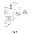
- Fig. 4 shows a modified example.
- the inlet 45a of the ozone-decomposing catalyst vessel 45 is connected downstream from the confluence point of the discharge ozone and the ozone-containing gas from the ozone-generating section 20, when the gas-induction valve 43 and the gas-discharging valve 44 are opened and the ozone-containing gas from the ozone-generating section 20 is introduced into the aspirator 34.
- the flow of gas within the circular conduit, which starts from the gas-liquid mixing vessel 31, passes the gas-discharging port 39, the communicating conduit 53 and the gas-induction conduit 36, and returns back to the gas-liquid mixing vessel 31, is sufficiently fast because of the suction (or aspiration) of the aspirator 34.
- ozone water and ozone gas are prevented from leaking by the positioning of the gas-discharging conduit and the bending shape of the water-discharging conduit.
- the water level becomes higher than the gas-discharging conduit, or there occurs a shortage of ozone water which would otherwise remain at a level to seal the section of the water-discharging conduit.
- the valves interposed along the water-supplying conduit may be opened/closed according to signals from the water-level sensor 70.
- the form of the gas-liquid mixing vessel is not limited to the above-mentioned example, but can have, for example, a configuration in which an opening is provided in the upper side surface of the inner cylinder and the ozone water overflows therefrom, or, in which the bottom surfaces of the inner cylinder and the outer cylinder are not flush with each other.
- the gas-liquid mixing vessel and the inner/outer cylinder are not limited to a cylindrical shape, and also, the gas-liquid mixing vessel may simply be divided into two sections, and one side may be taken as the inner vessel. According to such structure, the structure of the gas-liquid mixing vessel can be simplified to further reduce the manufacturing cost of the apparatus.
- ozone water producing apparatus of the above-mentioned example, it is possible to stably and continuously supply ozone water having a predetermined concentration for a long period of time.
- a more strict concentration control will be made possible by, for example, controlling the water temperature within the gas-liquid mixing vessel through a known feedback control, or, maintaining the water quality of the material water in a stable state by providing a sophisticated water-cleaning mechanism in the water-cleaning section.
- the ozone water producing apparatus of the present invention it becomes possible to provide, for example, a high-performance and compact ozone water producing apparatus which can effectively control the ozone concentration at low costs, by devising the structure of a gas-liquid mixing vessel for mixing ozone-containing gas and material water together, and/or the method of supplying gas and liquid to the vessel, without the need for a large-scale gas-liquid mixing vessel or a temperature control mechanism. Further, since a large amount of ozone water can continuously be supplied for a long period of time with consideration to safety, the apparatus is highly versatile. Therefore, cleansing using ozone water can become widespread to various purposes such as for industrial usage.
Landscapes
- Chemical & Material Sciences (AREA)
- Chemical Kinetics & Catalysis (AREA)
- Organic Chemistry (AREA)
- Inorganic Chemistry (AREA)
- Oxygen, Ozone, And Oxides In General (AREA)
- Treatment Of Water By Oxidation Or Reduction (AREA)
Priority Applications (3)
| Application Number | Priority Date | Filing Date | Title |
|---|---|---|---|
| JP2001013052A JP2002210340A (ja) | 2001-01-22 | 2001-01-22 | オゾン水製造装置 |
| EP02254788A EP1380537A1 (fr) | 2001-01-22 | 2002-07-09 | Dispositif de production d'un mélange eau-ozone et dispositif de production de mélanges gaz-liquide |
| US10/198,040 US20040011642A1 (en) | 2001-01-22 | 2002-07-18 | Ozone water producing apparatus and gas-liquid mixture producing apparatus |
Applications Claiming Priority (3)
| Application Number | Priority Date | Filing Date | Title |
|---|---|---|---|
| JP2001013052A JP2002210340A (ja) | 2001-01-22 | 2001-01-22 | オゾン水製造装置 |
| EP02254788A EP1380537A1 (fr) | 2001-01-22 | 2002-07-09 | Dispositif de production d'un mélange eau-ozone et dispositif de production de mélanges gaz-liquide |
| US10/198,040 US20040011642A1 (en) | 2001-01-22 | 2002-07-18 | Ozone water producing apparatus and gas-liquid mixture producing apparatus |
Publications (1)
| Publication Number | Publication Date |
|---|---|
| EP1380537A1 true EP1380537A1 (fr) | 2004-01-14 |
Family
ID=32329488
Family Applications (1)
| Application Number | Title | Priority Date | Filing Date |
|---|---|---|---|
| EP02254788A Withdrawn EP1380537A1 (fr) | 2001-01-22 | 2002-07-09 | Dispositif de production d'un mélange eau-ozone et dispositif de production de mélanges gaz-liquide |
Country Status (3)
| Country | Link |
|---|---|
| US (1) | US20040011642A1 (fr) |
| EP (1) | EP1380537A1 (fr) |
| JP (1) | JP2002210340A (fr) |
Cited By (5)
| Publication number | Priority date | Publication date | Assignee | Title |
|---|---|---|---|---|
| WO2008029027A1 (fr) * | 2006-09-08 | 2008-03-13 | Degremont | Procede et installation pour la mise en contact de l'ozone dans un flux de liquide, en particulier d'eau potable ou d'eau residuaire |
| RU2365104C1 (ru) * | 2008-04-21 | 2009-08-27 | Федеральное государственное образовательное учреждение высшего профессионального образования "Челябинский государственный агроинженерный университет" | Устройство для кормления пчел |
| RU2446681C2 (ru) * | 2010-01-11 | 2012-04-10 | Федеральное государственное образовательное учреждение высшего профессионального образования (ФГОУ ВПО) Челябинская государственная агроинженерная академия | Устройство для поения пчел на пасеке |
| RU2553875C2 (ru) * | 2013-08-16 | 2015-06-20 | Сергей Васильевич Лузан | Устройство для насыщения воды кислородом |
| WO2020024810A1 (fr) * | 2018-08-02 | 2020-02-06 | 崔立慧 | Dispositif de préparation d'eau ozonée |
Families Citing this family (14)
| Publication number | Priority date | Publication date | Assignee | Title |
|---|---|---|---|---|
| JP2002210340A (ja) * | 2001-01-22 | 2002-07-30 | Core Medical Kk | オゾン水製造装置 |
| JP3772860B2 (ja) * | 2003-07-16 | 2006-05-10 | マツダ株式会社 | 気体溶解装置 |
| TWI324528B (en) * | 2004-08-20 | 2010-05-11 | Huei Tarng Liou | Ozone on-line injection, reuse, and destruction system |
| JP4556564B2 (ja) * | 2004-09-01 | 2010-10-06 | マツダ株式会社 | 気体溶解装置 |
| WO2006038298A1 (fr) * | 2004-10-07 | 2006-04-13 | Grow Co., Ltd. | Appareil de production d’eau ozonee |
| CN100427645C (zh) * | 2005-09-21 | 2008-10-22 | 石坚 | 两侧等压式气水混合方法及其装置 |
| CN100545318C (zh) * | 2005-11-01 | 2009-09-30 | 株洲冶炼集团有限责任公司 | 一种高铋粗铅的电解方法 |
| US20070295021A1 (en) * | 2006-06-20 | 2007-12-27 | Albonia Innovative Technologies Ltd. | Apparatus and Method For Generating Water From an Air Stream |
| KR101134483B1 (ko) * | 2009-07-01 | 2012-04-13 | 이세한 | 과포화 세정수 생성기 |
| JP5575720B2 (ja) * | 2011-09-19 | 2014-08-20 | 株式会社日立製作所 | 液体処理装置 |
| JP2013203583A (ja) * | 2012-03-28 | 2013-10-07 | Sharp Corp | オゾン含有液生成装置およびこれを備えた洗浄装置 |
| JP2015182001A (ja) * | 2014-03-24 | 2015-10-22 | シャープ株式会社 | 溶解液生成装置及びそれを備えた衛生器具用洗浄装置 |
| WO2017060909A1 (fr) * | 2015-10-08 | 2017-04-13 | Aquallence Ltd Israel | Système de purification des eaux ménagères au point d'entrée |
| CN111188054B (zh) * | 2019-12-30 | 2025-02-18 | 慈溪市天泉电器科技有限公司 | 混气水体产生器结构 |
Citations (6)
| Publication number | Priority date | Publication date | Assignee | Title |
|---|---|---|---|---|
| JPH0859207A (ja) * | 1994-08-19 | 1996-03-05 | Tokico Ltd | オゾン水生成装置 |
| JPH1034174A (ja) * | 1996-07-23 | 1998-02-10 | Fuji Electric Co Ltd | Uチューブ型オゾン処理装置 |
| JP2000135423A (ja) * | 1998-10-29 | 2000-05-16 | Akio Tsubota | オゾン水製造装置 |
| US6231769B1 (en) * | 1997-06-17 | 2001-05-15 | L'air Liquide, Societe Anonyme Pour L'etude Et L'exploitation Des Procedes Georges Claude | Installation for producing ozonized water |
| US20020023866A1 (en) * | 2000-12-31 | 2002-02-28 | Barnes Ronald L. | Assembly for purifying water |
| JP2002210340A (ja) * | 2001-01-22 | 2002-07-30 | Core Medical Kk | オゾン水製造装置 |
Family Cites Families (1)
| Publication number | Priority date | Publication date | Assignee | Title |
|---|---|---|---|---|
| US6623635B2 (en) * | 1999-10-15 | 2003-09-23 | Ronald L. Barnes | Assembly for purifying water |
-
2001
- 2001-01-22 JP JP2001013052A patent/JP2002210340A/ja active Pending
-
2002
- 2002-07-09 EP EP02254788A patent/EP1380537A1/fr not_active Withdrawn
- 2002-07-18 US US10/198,040 patent/US20040011642A1/en not_active Abandoned
Patent Citations (6)
| Publication number | Priority date | Publication date | Assignee | Title |
|---|---|---|---|---|
| JPH0859207A (ja) * | 1994-08-19 | 1996-03-05 | Tokico Ltd | オゾン水生成装置 |
| JPH1034174A (ja) * | 1996-07-23 | 1998-02-10 | Fuji Electric Co Ltd | Uチューブ型オゾン処理装置 |
| US6231769B1 (en) * | 1997-06-17 | 2001-05-15 | L'air Liquide, Societe Anonyme Pour L'etude Et L'exploitation Des Procedes Georges Claude | Installation for producing ozonized water |
| JP2000135423A (ja) * | 1998-10-29 | 2000-05-16 | Akio Tsubota | オゾン水製造装置 |
| US20020023866A1 (en) * | 2000-12-31 | 2002-02-28 | Barnes Ronald L. | Assembly for purifying water |
| JP2002210340A (ja) * | 2001-01-22 | 2002-07-30 | Core Medical Kk | オゾン水製造装置 |
Non-Patent Citations (4)
| Title |
|---|
| PATENT ABSTRACTS OF JAPAN vol. 1996, no. 07 31 July 1996 (1996-07-31) * |
| PATENT ABSTRACTS OF JAPAN vol. 1998, no. 06 30 April 1998 (1998-04-30) * |
| PATENT ABSTRACTS OF JAPAN vol. 2000, no. 08 6 October 2000 (2000-10-06) * |
| PATENT ABSTRACTS OF JAPAN vol. 2002, no. 11 6 November 2002 (2002-11-06) * |
Cited By (8)
| Publication number | Priority date | Publication date | Assignee | Title |
|---|---|---|---|---|
| WO2008029027A1 (fr) * | 2006-09-08 | 2008-03-13 | Degremont | Procede et installation pour la mise en contact de l'ozone dans un flux de liquide, en particulier d'eau potable ou d'eau residuaire |
| FR2905608A1 (fr) * | 2006-09-08 | 2008-03-14 | Degremont Sa | Procede et installation pour la mise en contact de l'ozone dans un flux de liquide,en particulier d'eau potable ou d'eau residuaire. |
| CN101541407B (zh) * | 2006-09-08 | 2012-07-04 | 得利满公司 | 使臭氧与液流、特别是饮用水或废水的液流接触的方法和设备 |
| US8298418B2 (en) | 2006-09-08 | 2012-10-30 | Degremont | Method and installation for bringing ozone into contact with a flow of liquid, in particular a flow of drinking water or wastewater |
| RU2365104C1 (ru) * | 2008-04-21 | 2009-08-27 | Федеральное государственное образовательное учреждение высшего профессионального образования "Челябинский государственный агроинженерный университет" | Устройство для кормления пчел |
| RU2446681C2 (ru) * | 2010-01-11 | 2012-04-10 | Федеральное государственное образовательное учреждение высшего профессионального образования (ФГОУ ВПО) Челябинская государственная агроинженерная академия | Устройство для поения пчел на пасеке |
| RU2553875C2 (ru) * | 2013-08-16 | 2015-06-20 | Сергей Васильевич Лузан | Устройство для насыщения воды кислородом |
| WO2020024810A1 (fr) * | 2018-08-02 | 2020-02-06 | 崔立慧 | Dispositif de préparation d'eau ozonée |
Also Published As
| Publication number | Publication date |
|---|---|
| US20040011642A1 (en) | 2004-01-22 |
| JP2002210340A (ja) | 2002-07-30 |
Similar Documents
| Publication | Publication Date | Title |
|---|---|---|
| EP1380537A1 (fr) | Dispositif de production d'un mélange eau-ozone et dispositif de production de mélanges gaz-liquide | |
| US7029587B2 (en) | Water purification | |
| KR101901260B1 (ko) | 고수율 순수 이산화염소 제조 장치 | |
| CN114615953B (zh) | 具有臭氧化水系统的超声波洁牙机 | |
| KR101162535B1 (ko) | 소독부산물이 생성되지 않는 친환경 살균소독제인 이산화염소수의 제조장치 | |
| US20040055969A1 (en) | Water treatment system and method | |
| WO2006090869A1 (fr) | Procede de production d’eau sterile contenant de l’acide hypochloreux ou de l’acide chloreux en tant que composant principal et appareil pour celui-ci | |
| JP2016002533A (ja) | 原水に含まれる溶存酸素を原料としてオゾン水を製造するオゾン水の製造装置及びオゾン水の製造方法 | |
| JP2001137862A (ja) | オゾン水製造装置 | |
| EP1309515B1 (fr) | Procede de production d'eau de sterilisation contenant de l'ozone et appareil utilise dans ledit procede | |
| JP2008061700A (ja) | 脱臭・殺菌装置 | |
| US20040232004A1 (en) | Electrolytic gas generation method and electrolytic gas generation device | |
| JP7786683B2 (ja) | オゾン水の製造方法およびオゾン水の製造装置 | |
| JP2013094747A (ja) | オゾン液生成器及びオゾン液生成方法 | |
| JP2008086885A (ja) | 電解水生成装置 | |
| CN101124169A (zh) | 以次氯酸或者亚氯酸为主要成分的杀菌水的生成方法及其装置 | |
| KR102251971B1 (ko) | 동력원 없는 감압 방식 원료 공급 및 반응으로 폭발 위험성을 제거한 이산화염소 가스 제조 장치 및 제조 방법 | |
| JP2014095100A (ja) | オゾン水生成装置 | |
| JPH0910781A (ja) | 電解式オゾン水洗浄機 | |
| JPH10192855A (ja) | 電解水生成装置 | |
| JPH10235372A (ja) | オゾン水製造装置 | |
| JPH03254890A (ja) | オゾン水製造装置 | |
| KR20140103414A (ko) | 고농도 차아염소산수 생성 장치 및 이를 이용한 석션 소독 장치 | |
| KR100360593B1 (ko) | 오존수 제조 장치 | |
| JPH03221195A (ja) | オゾン水製造装置 |
Legal Events
| Date | Code | Title | Description |
|---|---|---|---|
| PUAI | Public reference made under article 153(3) epc to a published international application that has entered the european phase |
Free format text: ORIGINAL CODE: 0009012 |
|
| AK | Designated contracting states |
Kind code of ref document: A1 Designated state(s): AT BE BG CH CY CZ DE DK EE ES FI FR GB GR IE IT LI LU MC NL PT SE SK TR |
|
| AX | Request for extension of the european patent |
Extension state: AL LT LV MK RO SI |
|
| AKX | Designation fees paid | ||
| REG | Reference to a national code |
Ref country code: DE Ref legal event code: 8566 |
|
| STAA | Information on the status of an ep patent application or granted ep patent |
Free format text: STATUS: THE APPLICATION IS DEEMED TO BE WITHDRAWN |
|
| 18D | Application deemed to be withdrawn |
Effective date: 20040715 |