EP1380752A1 - Support isolateur de vibrations pour système d'entraínement d'un dispositif médical - Google Patents
Support isolateur de vibrations pour système d'entraínement d'un dispositif médical Download PDFInfo
- Publication number
- EP1380752A1 EP1380752A1 EP02015304A EP02015304A EP1380752A1 EP 1380752 A1 EP1380752 A1 EP 1380752A1 EP 02015304 A EP02015304 A EP 02015304A EP 02015304 A EP02015304 A EP 02015304A EP 1380752 A1 EP1380752 A1 EP 1380752A1
- Authority
- EP
- European Patent Office
- Prior art keywords
- holding device
- spring elements
- drive
- holder according
- inner holding
- Prior art date
- Legal status (The legal status is an assumption and is not a legal conclusion. Google has not performed a legal analysis and makes no representation as to the accuracy of the status listed.)
- Granted
Links
- 230000005484 gravity Effects 0.000 claims description 17
- 230000006835 compression Effects 0.000 claims description 7
- 238000007906 compression Methods 0.000 claims description 7
- 238000013016 damping Methods 0.000 description 5
- 230000001133 acceleration Effects 0.000 description 3
- 238000010521 absorption reaction Methods 0.000 description 1
- 230000002411 adverse Effects 0.000 description 1
- 238000005452 bending Methods 0.000 description 1
- 230000005540 biological transmission Effects 0.000 description 1
- 230000001419 dependent effect Effects 0.000 description 1
- 238000006073 displacement reaction Methods 0.000 description 1
- 230000000694 effects Effects 0.000 description 1
- 210000003746 feather Anatomy 0.000 description 1
- 210000002414 leg Anatomy 0.000 description 1
- 238000004519 manufacturing process Methods 0.000 description 1
- 239000002184 metal Substances 0.000 description 1
- 230000035939 shock Effects 0.000 description 1
- 239000007787 solid Substances 0.000 description 1
- 239000000725 suspension Substances 0.000 description 1
- 210000000689 upper leg Anatomy 0.000 description 1
Images

Classifications
-
- F—MECHANICAL ENGINEERING; LIGHTING; HEATING; WEAPONS; BLASTING
- F04—POSITIVE - DISPLACEMENT MACHINES FOR LIQUIDS; PUMPS FOR LIQUIDS OR ELASTIC FLUIDS
- F04B—POSITIVE-DISPLACEMENT MACHINES FOR LIQUIDS; PUMPS
- F04B39/00—Component parts, details, or accessories, of pumps or pumping systems specially adapted for elastic fluids, not otherwise provided for in, or of interest apart from, groups F04B25/00 - F04B37/00
- F04B39/0027—Pulsation and noise damping means
- F04B39/0044—Pulsation and noise damping means with vibration damping supports
-
- F—MECHANICAL ENGINEERING; LIGHTING; HEATING; WEAPONS; BLASTING
- F04—POSITIVE - DISPLACEMENT MACHINES FOR LIQUIDS; PUMPS FOR LIQUIDS OR ELASTIC FLUIDS
- F04B—POSITIVE-DISPLACEMENT MACHINES FOR LIQUIDS; PUMPS
- F04B53/00—Component parts, details or accessories not provided for in, or of interest apart from, groups F04B1/00 - F04B23/00 or F04B39/00 - F04B47/00
- F04B53/001—Noise damping
- F04B53/003—Noise damping by damping supports
Definitions
- the invention relates to a holder for low-vibration storage of Drives and in particular of pumps in medical devices.
- a holder for low-vibration Storage of drives and in particular of pumps in medical Devices to create the vibrations that occur can reliably degrade and has a longer shelf life.
- the holder according to the invention is intended for low-vibration Storage of drives in medical devices and in particular for low-vibration storage of pumps, such as pressure or Vacuum pumps in medical devices.
- the holder has a outer holding device and an inner holding device.
- the inner one Holding device is designed to receive the drive, d. H. the inner holding device is connected to the drive or the pump, for example connected by screws, clamping and / or locking means.
- the inner holding device is connected to the outer holding device only via Spring elements connected so that no solid, force-transmitting Connection between the outer and the inner holding device are provided. All fasteners between the inner and the outer holding device are resilient, so that occurring vibrations and vibrations can be damped.
- the spring elements are arranged so that they are together in transfer their forces of action in all three spatial directions can.
- the spring elements are arranged so that they transfer only one force in the direction of their line of action.
- the single ones Spring elements are thus kept free of transverse forces, which eventually lead to damage of the spring element could. Due to the spatial arrangement of the spring elements, a Vibration damping in every possible direction of movement of the reached inside holding device with respect to the outer holding device become.
- the possibility of movement of the inner Holding means relative to the outer holding device by the spatial arrangement of the spring elements, which is a power transmission in each spatial direction allows, to a minimum. In this way, even during transport or strong external Shocks an excessive displacement of the inner holding device and thus prevents one attached to this drive become. At the same time too great a movement of the individual spring elements, which could lead to damage of these, avoided.
- the inner holding device is firmly connected to the drive or formed as part of this.
- the housing the drive or a pump directly as an internal holding device act, the spring elements then directly to the drive or attack the pump.
- the spring elements preferably engage on the inner holding device at articulation points, which are symmetrical to the center of gravity of the drive are arranged. Furthermore, the articulation points are preferably as close as possible to the center of gravity of the drive or the pump. Further preferred are the articulation points and lines of action of the spring elements symmetrical to those through the center of gravity of the to be fastened Drive or the pump to be fastened Arranged symmetry or coordinate axes.
- the spring elements are preferably arranged in pairs, wherein for each spring element an oppositely acting spring element on the opposite side of the inner holding device is provided.
- the oppositely acting spring elements generate spring forces directed in opposite directions. In this way, an excessive movement of the pump at a occurring linear acceleration and overstretching or a Too much compression of the spring element, which leads to breakage of the spring element could be avoided. That's the situation of the drive at linear accelerations substantially stable.
- the spring elements are preferably as tension and / or compression springs educated.
- the spring elements may, for example, coil springs be, with preferably all arranged spring elements identical are formed and in particular have the same spring constant. In this way, a good vibration damping in all Directions and a stable position of the drive can be achieved.
- At least three, preferably six or eight spring elements are preferred provided to absorb the forces in all spatial directions to be able to.
- each spring element is arranged in the direction of one of three coordinate axes be so that the spring elements each at an angle are arranged at 90 ° to each other.
- Particularly preferred is the arrangement of eight spring elements, wherein the articulation points on the inner holding device define the vertices of a cuboid.
- the lines of action of the spring elements so that they are the center of gravity of the drive to be absorbed to cut.
- the eight spring elements are preferably symmetrical to Center of gravity of the drive arranged so that they together Can transmit forces in all three spatial directions. Continue to run the lines of action of the spring elements preferably symmetrical to passing through the center of gravity of the drive to be fastened right-angled coordinate axes. So in all sorts of ways Movement directions of the drive sufficient damping and Limitation of movement can be achieved, so that excessive Elongation or compression of the spring elements and an undesirable large deflection of the drive or the pump from the respective rest position is prevented.
- the lines of action of the eight spring elements each extend at an angle, preferably at substantially 90 ° to each other.
- all the spring elements extend in opposite directions Directions, allowing a spatial suspension of the drive is achieved in all spatial directions.
- the inner and outer holding means are preferably each U-shaped Formed bow.
- the U-shaped bracket are so intertwined set that their walls extend parallel to each other.
- the spring elements are preferably between the parallel lateral thighs of the U-shaped temples of the inner and the outer Holding device arranged.
- These holding devices are lightweight to manufacture, for example by bending a sheet metal section. Further allows this configuration good accessibility of the spring elements and the drive receiving interior of the inner holding device, since this space is open on three sides.
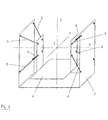
- FIG. 1 shows in a lateral view schematically the principal Structure of the holder for low-vibration mounting of drives and in particular of pumps in medical devices.
- the Holder has an outer holding device 2 and an inner holding device 4 on.
- the inner holding device 4 is for receiving a not shown drive, for example, in the form of a pump.
- a drive such as a motor or a pump
- the inner holding device 4 is with the inner holding device 4, for example by screwing or latching firmly connected.
- the inner holding device 4 Part of the drive to be stored or the pump to be stored be, for example, directly from the outer wall of a pump housing be formed.
- the inner holding device 4 is connected to the outer Holding device 2 only connected via eight spring elements 6.
- the spring elements 6 extend symmetrically to the center of gravity S a male pump and symmetrical to these Center of gravity S intersecting coordinate and symmetry axes X, Z, which run at right angles to each other. In the example shown extend the lines of action of the spring elements 6, which as a train or Compression springs are formed, substantially at an angle of 45 ° to the axes X, Z.
- the spring elements 6 are all formed identically, In particular, the springs used have the same spring constants on.
- the spring elements 6 are all identical as prestressed Tension springs formed, in particular, identical spring constants exhibit.
- spring elements 6 with different spring constants be used, in particular to a weight balance create.
- the vertically upwardly located spring elements 6 with a larger spring constant Be provided so that they can absorb weight despite the weight the inner holding device 4 and the drive mounted therein allow sufficient damping.
- compression springs which are located vertically below Form spring elements 6 with a larger spring constant.
- the vertically lower spring elements 6 as Compression springs and the vertically upwardly located spring elements 6 as Train springs, so that the of the inner holding device. 4 and a device stored therein (motor, pump, etc.) can be distributed evenly on all spring elements 6.
- a bias of the spring elements 6 evenly be formed so that optimal in all directions that achieves optimum damping properties in all spatial directions become.
- Fig. 2 shows a view of the arrangement of FIG. 1 in the direction of Arrow A in Fig. 1.
- the outer holder 2 is substantially as a U-shaped Bracket formed in the interior of a parallel to this bracket extending further U-shaped bracket as an inner holding device 4 (see also Fig. 1) is arranged.
- the lines of action of the spring elements 6 also with respect to the coordinate axis Y, which is normal to the axes X, Z and this intersects in the center of gravity S, essentially at an angle of 45 °.
- the articulation points of Spring elements 6 on the inner holding device 4 define the corner points a cuboid.
- the lines of action of the spring elements 6 run each obliquely to all three coordinate axes X, Y and Z. In the shown Example are the lines of action at an angle of 45 ° to the Coordinate axes inclined, but are also smaller or larger Angle possible. However, the lines of action of all spring elements run 6 preferably obliquely to all three coordinate axes X, Y and Z, so that the inner holding device 4 in all coordinate directions is held resiliently.
- Fig. 3 shows a plan view of the arrangement of FIG. 1 in the direction of the arrow B in Fig. 1. Also in this view, the oblique course of Effect lines of the spring elements 6 with respect to the coordinate axis X. and Y to recognize.
- the spring elements 6 are on the inner Holding device as close to the center of gravity S of a to be accommodated drive to the deflection of the springs to be kept as low as possible during operation.
- Fig. 4 shows a schematic overall perspective view of the invention Bracket. It can be seen that the outer holding device 2 and the inner holding device 4 each as substantially U-shaped elements are formed, which are arranged one inside the other are that their legs or side surfaces each parallel to each other extend.
- the spring elements 6 are arranged spatially in such a way that their lines of action in each case essentially on the Center of gravity S to extend and preferably in the center of gravity S or near it.
Landscapes
- Engineering & Computer Science (AREA)
- Mechanical Engineering (AREA)
- General Engineering & Computer Science (AREA)
- Vibration Prevention Devices (AREA)
- Springs (AREA)
- Percussion Or Vibration Massage (AREA)
- Apparatuses For Generation Of Mechanical Vibrations (AREA)
Priority Applications (4)
| Application Number | Priority Date | Filing Date | Title |
|---|---|---|---|
| DE50209972T DE50209972D1 (de) | 2002-07-10 | 2002-07-10 | Halterung zur vibrationsarmen Lagerung von Antrieben in medizinischen Geräten |
| EP02015304A EP1380752B1 (fr) | 2002-07-10 | 2002-07-10 | Support isolateur de vibrations pour système d'entraînement d'un dispositif médical |
| ES02015304T ES2284751T3 (es) | 2002-07-10 | 2002-07-10 | Soporte de fijacion para el alojamiento aislado de vibracions de accionamientos en aparatos medicos. |
| AT02015304T ATE360145T1 (de) | 2002-07-10 | 2002-07-10 | Halterung zur vibrationsarmen lagerung von antrieben in medizinischen geräten |
Applications Claiming Priority (1)
| Application Number | Priority Date | Filing Date | Title |
|---|---|---|---|
| EP02015304A EP1380752B1 (fr) | 2002-07-10 | 2002-07-10 | Support isolateur de vibrations pour système d'entraînement d'un dispositif médical |
Publications (2)
| Publication Number | Publication Date |
|---|---|
| EP1380752A1 true EP1380752A1 (fr) | 2004-01-14 |
| EP1380752B1 EP1380752B1 (fr) | 2007-04-18 |
Family
ID=29724421
Family Applications (1)
| Application Number | Title | Priority Date | Filing Date |
|---|---|---|---|
| EP02015304A Expired - Lifetime EP1380752B1 (fr) | 2002-07-10 | 2002-07-10 | Support isolateur de vibrations pour système d'entraînement d'un dispositif médical |
Country Status (4)
| Country | Link |
|---|---|
| EP (1) | EP1380752B1 (fr) |
| AT (1) | ATE360145T1 (fr) |
| DE (1) | DE50209972D1 (fr) |
| ES (1) | ES2284751T3 (fr) |
Cited By (2)
| Publication number | Priority date | Publication date | Assignee | Title |
|---|---|---|---|---|
| WO2020001872A1 (fr) * | 2018-06-29 | 2020-01-02 | Contitech Vibration Control Gmbh | Mécanisme d'atténuation de vibrations, et véhicule pourvu dudit mécanisme d'atténuation de vibrations monté sur celui-ci |
| EP3677777A4 (fr) * | 2017-08-28 | 2020-08-19 | Panasonic Intellectual Property Management Co., Ltd. | Structure support élastique |
Citations (3)
| Publication number | Priority date | Publication date | Assignee | Title |
|---|---|---|---|---|
| JPS58187589A (ja) * | 1982-04-26 | 1983-11-01 | Matsushita Electric Ind Co Ltd | 密閉型電動圧縮機の防振装置 |
| US5697678A (en) * | 1993-05-26 | 1997-12-16 | Robert Bosch Gmbh | Hydraulic unit supported in such a way as to damp vibration and forming part of a slip-controlled brake system |
| JPH11247936A (ja) * | 1998-03-05 | 1999-09-14 | Sony Corp | 防振装置 |
-
2002
- 2002-07-10 EP EP02015304A patent/EP1380752B1/fr not_active Expired - Lifetime
- 2002-07-10 DE DE50209972T patent/DE50209972D1/de not_active Expired - Lifetime
- 2002-07-10 ES ES02015304T patent/ES2284751T3/es not_active Expired - Lifetime
- 2002-07-10 AT AT02015304T patent/ATE360145T1/de not_active IP Right Cessation
Patent Citations (3)
| Publication number | Priority date | Publication date | Assignee | Title |
|---|---|---|---|---|
| JPS58187589A (ja) * | 1982-04-26 | 1983-11-01 | Matsushita Electric Ind Co Ltd | 密閉型電動圧縮機の防振装置 |
| US5697678A (en) * | 1993-05-26 | 1997-12-16 | Robert Bosch Gmbh | Hydraulic unit supported in such a way as to damp vibration and forming part of a slip-controlled brake system |
| JPH11247936A (ja) * | 1998-03-05 | 1999-09-14 | Sony Corp | 防振装置 |
Non-Patent Citations (2)
| Title |
|---|
| PATENT ABSTRACTS OF JAPAN vol. 008, no. 032 (M - 275) 10 February 1984 (1984-02-10) * |
| PATENT ABSTRACTS OF JAPAN vol. 1999, no. 14 22 December 1999 (1999-12-22) * |
Cited By (3)
| Publication number | Priority date | Publication date | Assignee | Title |
|---|---|---|---|---|
| EP3677777A4 (fr) * | 2017-08-28 | 2020-08-19 | Panasonic Intellectual Property Management Co., Ltd. | Structure support élastique |
| WO2020001872A1 (fr) * | 2018-06-29 | 2020-01-02 | Contitech Vibration Control Gmbh | Mécanisme d'atténuation de vibrations, et véhicule pourvu dudit mécanisme d'atténuation de vibrations monté sur celui-ci |
| CN110657194A (zh) * | 2018-06-29 | 2020-01-07 | 康迪泰克(中国)橡塑技术有限公司 | 一种减振机构及安装有所述减振机构的车辆 |
Also Published As
| Publication number | Publication date |
|---|---|
| DE50209972D1 (de) | 2007-05-31 |
| ATE360145T1 (de) | 2007-05-15 |
| EP1380752B1 (fr) | 2007-04-18 |
| ES2284751T3 (es) | 2007-11-16 |
Similar Documents
| Publication | Publication Date | Title |
|---|---|---|
| DE69804548T2 (de) | Computergehäuse | |
| EP1620233B1 (fr) | Machine-outil manuelle electrique comportant un bloc d'accumulateur | |
| DE602004003739T2 (de) | Stossdämpfendes Element, Stossdämpfendes Verfahren für eine elektronische Vorrichtung welches dieses Element benutzt, und für dieses Element und dieses Verfahren angepasste elektronische Vorrichtung | |
| EP0923684A2 (fr) | Dispositif a ressort pour le positionnement, dans un boitier, d'un appareil sensible aux vibrations et aux chocs fixe sur un support | |
| WO2003003106A1 (fr) | Dispositif de retenue permettant un montage flottant d'un ecran plat et dispositif d'affichage electronique comprenant un ecran plat et un dispositif de retenue | |
| DE69918969T2 (de) | Motorlager | |
| DE4310944C2 (de) | Luftdichter Kompressor | |
| EP2639476A1 (fr) | Amortisseur pour le stockage d'un objet dans ou sur un véhicule | |
| EP1380752B1 (fr) | Support isolateur de vibrations pour système d'entraînement d'un dispositif médical | |
| EP0762012B1 (fr) | Amortisseur dynamique | |
| DE102019200049A1 (de) | A suspension assembly | |
| EP2301385A1 (fr) | Entraînement pour meuble | |
| DE102020129399A1 (de) | Federung eines Nebenaggregates | |
| DE102008052424B4 (de) | Vibrationstilgersystem | |
| DE60209233T2 (de) | Schwingungsdämpfer zur dämpfung von schwingungen mit niedrigen frequenzen | |
| DE202006012434U1 (de) | Schienenverstellsystem mit Spindel und Spindellagerung | |
| DE102019109171A1 (de) | Träger-Vorrichtung zur Anbindung einer Antriebskomponente an ein Fahrzeug | |
| EP1256955B1 (fr) | Dispositif de fixation d'unité de disques | |
| EP2423015A1 (fr) | Dispositif pour supporter un agrégat de façon à minimiser les vibrations | |
| DE69201124T2 (de) | Elastische Aufhängungsvorrichtung mit verschiedenen Steifheiten zur Lagerung eines Geräts. | |
| EP1099876A1 (fr) | Dispositif amortisseur pour supporter un objet | |
| DE202013104449U1 (de) | Schwingungsisolator | |
| DE102018210153A1 (de) | Entkopplungsanordnung für einen Kompressor in einem Kraftfahrzeug | |
| EP4291832B1 (fr) | Pompe à chaleur | |
| DE2308079A1 (de) | Elastische aggregataufhaengung |
Legal Events
| Date | Code | Title | Description |
|---|---|---|---|
| PUAI | Public reference made under article 153(3) epc to a published international application that has entered the european phase |
Free format text: ORIGINAL CODE: 0009012 |
|
| 17P | Request for examination filed |
Effective date: 20030228 |
|
| AK | Designated contracting states |
Kind code of ref document: A1 Designated state(s): AT BE BG CH CY CZ DE DK EE ES FI FR GB GR IE IT LI LU MC NL PT SE SK TR |
|
| AX | Request for extension of the european patent |
Extension state: AL LT LV MK RO SI |
|
| AKX | Designation fees paid |
Designated state(s): AT BE BG CH CY CZ DE DK EE ES FI FR GB GR IE IT LI LU MC NL PT SE SK TR |
|
| GRAP | Despatch of communication of intention to grant a patent |
Free format text: ORIGINAL CODE: EPIDOSNIGR1 |
|
| GRAS | Grant fee paid |
Free format text: ORIGINAL CODE: EPIDOSNIGR3 |
|
| GRAA | (expected) grant |
Free format text: ORIGINAL CODE: 0009210 |
|
| AK | Designated contracting states |
Kind code of ref document: B1 Designated state(s): AT BE BG CH CY CZ DE DK EE ES FI FR GB GR IE IT LI LU MC NL PT SE SK TR |
|
| PG25 | Lapsed in a contracting state [announced via postgrant information from national office to epo] |
Ref country code: FI Free format text: LAPSE BECAUSE OF FAILURE TO SUBMIT A TRANSLATION OF THE DESCRIPTION OR TO PAY THE FEE WITHIN THE PRESCRIBED TIME-LIMIT Effective date: 20070418 |
|
| REG | Reference to a national code |
Ref country code: CH Ref legal event code: EP |
|
| REG | Reference to a national code |
Ref country code: IE Ref legal event code: FG4D Free format text: LANGUAGE OF EP DOCUMENT: GERMAN |
|
| REF | Corresponds to: |
Ref document number: 50209972 Country of ref document: DE Date of ref document: 20070531 Kind code of ref document: P |
|
| GBT | Gb: translation of ep patent filed (gb section 77(6)(a)/1977) |
Effective date: 20070517 |
|
| REG | Reference to a national code |
Ref country code: CH Ref legal event code: NV Representative=s name: ISLER & PEDRAZZINI AG |
|
| PG25 | Lapsed in a contracting state [announced via postgrant information from national office to epo] |
Ref country code: SE Free format text: LAPSE BECAUSE OF FAILURE TO SUBMIT A TRANSLATION OF THE DESCRIPTION OR TO PAY THE FEE WITHIN THE PRESCRIBED TIME-LIMIT Effective date: 20070718 |
|
| PG25 | Lapsed in a contracting state [announced via postgrant information from national office to epo] |
Ref country code: PT Free format text: LAPSE BECAUSE OF FAILURE TO SUBMIT A TRANSLATION OF THE DESCRIPTION OR TO PAY THE FEE WITHIN THE PRESCRIBED TIME-LIMIT Effective date: 20070918 |
|
| REG | Reference to a national code |
Ref country code: CH Ref legal event code: PCAR Free format text: ISLER & PEDRAZZINI AG;POSTFACH 1772;8027 ZUERICH (CH) |
|
| ET | Fr: translation filed | ||
| REG | Reference to a national code |
Ref country code: ES Ref legal event code: FG2A Ref document number: 2284751 Country of ref document: ES Kind code of ref document: T3 |
|
| REG | Reference to a national code |
Ref country code: IE Ref legal event code: FD4D |
|
| PG25 | Lapsed in a contracting state [announced via postgrant information from national office to epo] |
Ref country code: DK Free format text: LAPSE BECAUSE OF FAILURE TO SUBMIT A TRANSLATION OF THE DESCRIPTION OR TO PAY THE FEE WITHIN THE PRESCRIBED TIME-LIMIT Effective date: 20070418 Ref country code: CZ Free format text: LAPSE BECAUSE OF FAILURE TO SUBMIT A TRANSLATION OF THE DESCRIPTION OR TO PAY THE FEE WITHIN THE PRESCRIBED TIME-LIMIT Effective date: 20070418 Ref country code: BG Free format text: LAPSE BECAUSE OF FAILURE TO SUBMIT A TRANSLATION OF THE DESCRIPTION OR TO PAY THE FEE WITHIN THE PRESCRIBED TIME-LIMIT Effective date: 20070718 Ref country code: IE Free format text: LAPSE BECAUSE OF FAILURE TO SUBMIT A TRANSLATION OF THE DESCRIPTION OR TO PAY THE FEE WITHIN THE PRESCRIBED TIME-LIMIT Effective date: 20070418 |
|
| PLBE | No opposition filed within time limit |
Free format text: ORIGINAL CODE: 0009261 |
|
| STAA | Information on the status of an ep patent application or granted ep patent |
Free format text: STATUS: NO OPPOSITION FILED WITHIN TIME LIMIT |
|
| PG25 | Lapsed in a contracting state [announced via postgrant information from national office to epo] |
Ref country code: SK Free format text: LAPSE BECAUSE OF FAILURE TO SUBMIT A TRANSLATION OF THE DESCRIPTION OR TO PAY THE FEE WITHIN THE PRESCRIBED TIME-LIMIT Effective date: 20070418 |
|
| 26N | No opposition filed |
Effective date: 20080121 |
|
| PG25 | Lapsed in a contracting state [announced via postgrant information from national office to epo] |
Ref country code: GR Free format text: LAPSE BECAUSE OF FAILURE TO SUBMIT A TRANSLATION OF THE DESCRIPTION OR TO PAY THE FEE WITHIN THE PRESCRIBED TIME-LIMIT Effective date: 20070719 Ref country code: MC Free format text: LAPSE BECAUSE OF NON-PAYMENT OF DUE FEES Effective date: 20070731 |
|
| PG25 | Lapsed in a contracting state [announced via postgrant information from national office to epo] |
Ref country code: AT Free format text: LAPSE BECAUSE OF NON-PAYMENT OF DUE FEES Effective date: 20070710 |
|
| PG25 | Lapsed in a contracting state [announced via postgrant information from national office to epo] |
Ref country code: EE Free format text: LAPSE BECAUSE OF FAILURE TO SUBMIT A TRANSLATION OF THE DESCRIPTION OR TO PAY THE FEE WITHIN THE PRESCRIBED TIME-LIMIT Effective date: 20070418 |
|
| PG25 | Lapsed in a contracting state [announced via postgrant information from national office to epo] |
Ref country code: CY Free format text: LAPSE BECAUSE OF FAILURE TO SUBMIT A TRANSLATION OF THE DESCRIPTION OR TO PAY THE FEE WITHIN THE PRESCRIBED TIME-LIMIT Effective date: 20070418 |
|
| PG25 | Lapsed in a contracting state [announced via postgrant information from national office to epo] |
Ref country code: TR Free format text: LAPSE BECAUSE OF FAILURE TO SUBMIT A TRANSLATION OF THE DESCRIPTION OR TO PAY THE FEE WITHIN THE PRESCRIBED TIME-LIMIT Effective date: 20070418 |
|
| REG | Reference to a national code |
Ref country code: FR Ref legal event code: PLFP Year of fee payment: 15 |
|
| REG | Reference to a national code |
Ref country code: FR Ref legal event code: PLFP Year of fee payment: 16 |
|
| REG | Reference to a national code |
Ref country code: FR Ref legal event code: PLFP Year of fee payment: 17 |
|
| PGFP | Annual fee paid to national office [announced via postgrant information from national office to epo] |
Ref country code: NL Payment date: 20190722 Year of fee payment: 18 Ref country code: LU Payment date: 20190722 Year of fee payment: 18 |
|
| PGFP | Annual fee paid to national office [announced via postgrant information from national office to epo] |
Ref country code: IT Payment date: 20190723 Year of fee payment: 18 Ref country code: FR Payment date: 20190724 Year of fee payment: 18 Ref country code: ES Payment date: 20190822 Year of fee payment: 18 |
|
| PGFP | Annual fee paid to national office [announced via postgrant information from national office to epo] |
Ref country code: BE Payment date: 20190722 Year of fee payment: 18 |
|
| PGFP | Annual fee paid to national office [announced via postgrant information from national office to epo] |
Ref country code: GB Payment date: 20190725 Year of fee payment: 18 |
|
| PGFP | Annual fee paid to national office [announced via postgrant information from national office to epo] |
Ref country code: CH Payment date: 20190725 Year of fee payment: 18 |
|
| REG | Reference to a national code |
Ref country code: DE Ref legal event code: R084 Ref document number: 50209972 Country of ref document: DE |
|
| PGFP | Annual fee paid to national office [announced via postgrant information from national office to epo] |
Ref country code: DE Payment date: 20200723 Year of fee payment: 19 |
|
| REG | Reference to a national code |
Ref country code: CH Ref legal event code: PL |
|
| REG | Reference to a national code |
Ref country code: NL Ref legal event code: MM Effective date: 20200801 |
|
| GBPC | Gb: european patent ceased through non-payment of renewal fee |
Effective date: 20200710 |
|
| REG | Reference to a national code |
Ref country code: BE Ref legal event code: MM Effective date: 20200731 |
|
| PG25 | Lapsed in a contracting state [announced via postgrant information from national office to epo] |
Ref country code: GB Free format text: LAPSE BECAUSE OF NON-PAYMENT OF DUE FEES Effective date: 20200710 Ref country code: FR Free format text: LAPSE BECAUSE OF NON-PAYMENT OF DUE FEES Effective date: 20200731 Ref country code: NL Free format text: LAPSE BECAUSE OF NON-PAYMENT OF DUE FEES Effective date: 20200801 Ref country code: LU Free format text: LAPSE BECAUSE OF NON-PAYMENT OF DUE FEES Effective date: 20200710 Ref country code: CH Free format text: LAPSE BECAUSE OF NON-PAYMENT OF DUE FEES Effective date: 20200731 Ref country code: LI Free format text: LAPSE BECAUSE OF NON-PAYMENT OF DUE FEES Effective date: 20200731 |
|
| PG25 | Lapsed in a contracting state [announced via postgrant information from national office to epo] |
Ref country code: BE Free format text: LAPSE BECAUSE OF NON-PAYMENT OF DUE FEES Effective date: 20200731 |
|
| REG | Reference to a national code |
Ref country code: ES Ref legal event code: FD2A Effective date: 20211202 |
|
| PG25 | Lapsed in a contracting state [announced via postgrant information from national office to epo] |
Ref country code: ES Free format text: LAPSE BECAUSE OF NON-PAYMENT OF DUE FEES Effective date: 20200711 |
|
| REG | Reference to a national code |
Ref country code: DE Ref legal event code: R119 Ref document number: 50209972 Country of ref document: DE |
|
| PG25 | Lapsed in a contracting state [announced via postgrant information from national office to epo] |
Ref country code: IT Free format text: LAPSE BECAUSE OF NON-PAYMENT OF DUE FEES Effective date: 20200710 Ref country code: DE Free format text: LAPSE BECAUSE OF NON-PAYMENT OF DUE FEES Effective date: 20220201 |