EP1380771A2 - Convertisseur de couple hydrodynamique avec un stator et son procédé de fabrication - Google Patents
Convertisseur de couple hydrodynamique avec un stator et son procédé de fabrication Download PDFInfo
- Publication number
- EP1380771A2 EP1380771A2 EP03012383A EP03012383A EP1380771A2 EP 1380771 A2 EP1380771 A2 EP 1380771A2 EP 03012383 A EP03012383 A EP 03012383A EP 03012383 A EP03012383 A EP 03012383A EP 1380771 A2 EP1380771 A2 EP 1380771A2
- Authority
- EP
- European Patent Office
- Prior art keywords
- sealing
- outer ring
- ring
- freewheel
- stator
- Prior art date
- Legal status (The legal status is an assumption and is not a legal conclusion. Google has not performed a legal analysis and makes no representation as to the accuracy of the status listed.)
- Withdrawn
Links
- 238000004519 manufacturing process Methods 0.000 title claims abstract description 23
- 238000007789 sealing Methods 0.000 claims abstract description 111
- 229920002430 Fibre-reinforced plastic Polymers 0.000 claims abstract description 7
- 239000011151 fibre-reinforced plastic Substances 0.000 claims abstract description 7
- 239000000463 material Substances 0.000 claims description 23
- 238000005266 casting Methods 0.000 claims description 17
- 238000000034 method Methods 0.000 claims description 13
- 238000000465 moulding Methods 0.000 claims description 9
- 239000004033 plastic Substances 0.000 claims description 4
- 229920003023 plastic Polymers 0.000 claims description 4
- 239000002131 composite material Substances 0.000 abstract description 4
- 229910052751 metal Inorganic materials 0.000 description 7
- 239000002184 metal Substances 0.000 description 7
- 238000005520 cutting process Methods 0.000 description 5
- 238000003754 machining Methods 0.000 description 5
- 238000003825 pressing Methods 0.000 description 5
- 238000001816 cooling Methods 0.000 description 4
- 239000011344 liquid material Substances 0.000 description 4
- 239000000314 lubricant Substances 0.000 description 4
- 238000004080 punching Methods 0.000 description 4
- 238000007514 turning Methods 0.000 description 4
- 239000011324 bead Substances 0.000 description 3
- 230000005540 biological transmission Effects 0.000 description 3
- 239000002826 coolant Substances 0.000 description 3
- 238000004512 die casting Methods 0.000 description 3
- 238000005242 forging Methods 0.000 description 3
- 238000005304 joining Methods 0.000 description 3
- 230000001154 acute effect Effects 0.000 description 2
- 230000000694 effects Effects 0.000 description 2
- 238000005516 engineering process Methods 0.000 description 2
- 239000000835 fiber Substances 0.000 description 2
- 238000002347 injection Methods 0.000 description 2
- 239000007924 injection Substances 0.000 description 2
- 238000001746 injection moulding Methods 0.000 description 2
- 230000010354 integration Effects 0.000 description 2
- 239000007788 liquid Substances 0.000 description 2
- 238000012805 post-processing Methods 0.000 description 2
- 238000005507 spraying Methods 0.000 description 2
- 229920001169 thermoplastic Polymers 0.000 description 2
- 229920001187 thermosetting polymer Polymers 0.000 description 2
- 239000004416 thermosoftening plastic Substances 0.000 description 2
- 229920000965 Duroplast Polymers 0.000 description 1
- 239000004638 Duroplast Substances 0.000 description 1
- 229920000271 Kevlar® Polymers 0.000 description 1
- FYYHWMGAXLPEAU-UHFFFAOYSA-N Magnesium Chemical compound [Mg] FYYHWMGAXLPEAU-UHFFFAOYSA-N 0.000 description 1
- 229910000831 Steel Inorganic materials 0.000 description 1
- 238000005299 abrasion Methods 0.000 description 1
- 229910052782 aluminium Inorganic materials 0.000 description 1
- XAGFODPZIPBFFR-UHFFFAOYSA-N aluminium Chemical compound [Al] XAGFODPZIPBFFR-UHFFFAOYSA-N 0.000 description 1
- 238000004873 anchoring Methods 0.000 description 1
- 230000001419 dependent effect Effects 0.000 description 1
- 239000003365 glass fiber Substances 0.000 description 1
- 238000003780 insertion Methods 0.000 description 1
- 230000037431 insertion Effects 0.000 description 1
- 239000004761 kevlar Substances 0.000 description 1
- 238000005461 lubrication Methods 0.000 description 1
- 229910052749 magnesium Inorganic materials 0.000 description 1
- 239000011777 magnesium Substances 0.000 description 1
- 238000005121 nitriding Methods 0.000 description 1
- 230000002265 prevention Effects 0.000 description 1
- 238000012545 processing Methods 0.000 description 1
- 238000005488 sandblasting Methods 0.000 description 1
- 239000007787 solid Substances 0.000 description 1
- 239000010959 steel Substances 0.000 description 1
Images






Classifications
-
- F—MECHANICAL ENGINEERING; LIGHTING; HEATING; WEAPONS; BLASTING
- F16—ENGINEERING ELEMENTS AND UNITS; GENERAL MEASURES FOR PRODUCING AND MAINTAINING EFFECTIVE FUNCTIONING OF MACHINES OR INSTALLATIONS; THERMAL INSULATION IN GENERAL
- F16H—GEARING
- F16H41/00—Rotary fluid gearing of the hydrokinetic type
- F16H41/24—Details
-
- F—MECHANICAL ENGINEERING; LIGHTING; HEATING; WEAPONS; BLASTING
- F16—ENGINEERING ELEMENTS AND UNITS; GENERAL MEASURES FOR PRODUCING AND MAINTAINING EFFECTIVE FUNCTIONING OF MACHINES OR INSTALLATIONS; THERMAL INSULATION IN GENERAL
- F16H—GEARING
- F16H41/00—Rotary fluid gearing of the hydrokinetic type
- F16H41/24—Details
- F16H2041/246—Details relating to one way clutch of the stator
-
- F—MECHANICAL ENGINEERING; LIGHTING; HEATING; WEAPONS; BLASTING
- F16—ENGINEERING ELEMENTS AND UNITS; GENERAL MEASURES FOR PRODUCING AND MAINTAINING EFFECTIVE FUNCTIONING OF MACHINES OR INSTALLATIONS; THERMAL INSULATION IN GENERAL
- F16H—GEARING
- F16H45/00—Combinations of fluid gearings for conveying rotary motion with couplings or clutches
- F16H45/02—Combinations of fluid gearings for conveying rotary motion with couplings or clutches with mechanical clutches for bridging a fluid gearing of the hydrokinetic type
- F16H2045/0221—Combinations of fluid gearings for conveying rotary motion with couplings or clutches with mechanical clutches for bridging a fluid gearing of the hydrokinetic type with damping means
- F16H2045/0247—Combinations of fluid gearings for conveying rotary motion with couplings or clutches with mechanical clutches for bridging a fluid gearing of the hydrokinetic type with damping means having a turbine with hydrodynamic damping means
-
- F—MECHANICAL ENGINEERING; LIGHTING; HEATING; WEAPONS; BLASTING
- F16—ENGINEERING ELEMENTS AND UNITS; GENERAL MEASURES FOR PRODUCING AND MAINTAINING EFFECTIVE FUNCTIONING OF MACHINES OR INSTALLATIONS; THERMAL INSULATION IN GENERAL
- F16H—GEARING
- F16H45/00—Combinations of fluid gearings for conveying rotary motion with couplings or clutches
- F16H45/02—Combinations of fluid gearings for conveying rotary motion with couplings or clutches with mechanical clutches for bridging a fluid gearing of the hydrokinetic type
- F16H2045/0273—Combinations of fluid gearings for conveying rotary motion with couplings or clutches with mechanical clutches for bridging a fluid gearing of the hydrokinetic type characterised by the type of the friction surface of the lock-up clutch
- F16H2045/0284—Multiple disk type lock-up clutch
-
- F—MECHANICAL ENGINEERING; LIGHTING; HEATING; WEAPONS; BLASTING
- F16—ENGINEERING ELEMENTS AND UNITS; GENERAL MEASURES FOR PRODUCING AND MAINTAINING EFFECTIVE FUNCTIONING OF MACHINES OR INSTALLATIONS; THERMAL INSULATION IN GENERAL
- F16H—GEARING
- F16H2200/00—Transmissions for multiple ratios
- F16H2200/003—Transmissions for multiple ratios characterised by the number of forward speeds
- F16H2200/0052—Transmissions for multiple ratios characterised by the number of forward speeds the gear ratios comprising six forward speeds
-
- F—MECHANICAL ENGINEERING; LIGHTING; HEATING; WEAPONS; BLASTING
- F16—ENGINEERING ELEMENTS AND UNITS; GENERAL MEASURES FOR PRODUCING AND MAINTAINING EFFECTIVE FUNCTIONING OF MACHINES OR INSTALLATIONS; THERMAL INSULATION IN GENERAL
- F16H—GEARING
- F16H45/00—Combinations of fluid gearings for conveying rotary motion with couplings or clutches
- F16H45/02—Combinations of fluid gearings for conveying rotary motion with couplings or clutches with mechanical clutches for bridging a fluid gearing of the hydrokinetic type
Definitions
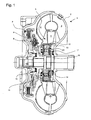
- the invention relates according to the preamble of claim 1 a hydrodynamic torque converter with a stator. Furthermore, the invention according to the preamble of Claim 12, a manufacturing method for such Stator.
- the object of the invention is a respect to the transmittable torque and the freewheeling function high quality, yet inexpensive to be manufactured stator to accomplish.
- An advantage of the invention is that the non-cutting Integration of a finished freewheel outer ring in the Diffuser is enabled.
- the stator is called inexpensive casting made.
- a Die casting of the diffuser made of aluminum, magnesium or thermoplastic or thermosetting plastic is allows.
- the cast guide wheel or its blade ring must not necessarily machined.
- post-processing can Balancing the unit stator / freewheel outer ring necessary his.
- such a balancing in the freewheel outer ring be minimized particularly advantageous manner. This is because the negative mold or the tool for Pouring / spraying the unit stator / freewheel outer ring after can be reworked a first trial cast.
- the stator is cast around a freewheel outer ring or sprayed, which has several hardened Einzelklemmbahnen.
- Freewheels with freewheel outer rings on the inside Single clamps have, are higher quality than freewheels with freewheel outer rings, whose inside is circular. This High quality is due to the fact that at the same Outside dimensions, a higher torque can be transmitted and the reliability in case of overload is better.
- the Hardening of single webs can be a surface hardening, such as for example, a case hardening or nitriding. Further can the complete material of the freewheel outer ring be through-hardened.
- the bearing inner ring the relative to this rotatable Leitradnabe both radial and store axially, with appropriate choice of material a Slide bearing particularly space-saving and cost-effective is realizable.
- Both the cast-in freewheel outer ring, as well as the Inner bearing ring can in a particularly advantageous manner Be made sintered metal.
- Claim 7 relates to a particularly advantageous Embodiment of the invention, in which the high Torque transmission at the joint between the stator and Freewheel outer ring of the freewheel through the Exterior contour design of the freewheel outer ring accomplished becomes.
- a toothing in the outer contour be forged the freewheel outer ring, which in the casting cast around the stator or molded in the case of die casting becomes.
- a toothing can be any shapes, such as For example, be provided coarse humps. On Forging these arbitrary shapes is particularly cost effective, wherein due to the connection by casting with cast material a post-processing of the cusps, gears, etc. is eliminated.
- Claim 3 shows a particularly advantageous Embodiment of the invention, in which a sealing ring Prevents liquid material from being pressed / poured into the Freewheeling space arrives and there with the Einzelklemmbahnen the Freewheel outer ring comes into contact and "baked" to this.
- the device claims 4 and 8 to 10 and the Process claims 13 to 18 show particularly advantageous embodiments, which in a particularly high degree prevent liquid material from pouring with the Einzelklemmbahnen the freewheel outer ring comes into contact and there "caked".
- the sealing ring can even be made of cast material be overmoulded / encapsulated without this casting material on Freewheel outer ring "baked". For this purpose, the negative form or having the casting tool corresponding sealing edges.
- Claim 11 shows a particularly inexpensive and lightweight shape of the stator as a component made of fiber-reinforced Plastic. In this case, no wear occurs in an advantageous manner on abrasionsripen fiber reinforced plastic, since the radial and axial bearing of the sealing ring or the Washer is adopted.
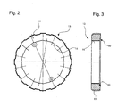
- Fig. 2 and Fig. 3 show the freewheel outer ring 13 as Item.
- Two of the cylindrical rollers 12 are exemplary in roll-over position - i. in the case of centrifugal concern on the Freewheel outer ring 13 - marked.
- the recess 20 of the Freewheel outer ring 13 is sharp at the outer edge 30 perpendicular to the inner edge 70.
- Fig. 4 and its detail Fig. 5 show, as in a first Manufacturing process step, the sealing washer 17 in the Depression 20 of the freewheel outer ring 13 is pressed. In the recess 20 is the sealing washer 17 before this pressing loosely inserted.
- pressing the sealing washer 17 in Freewheel outer ring 13 between an axially displaceable Stamp 21 and as an abutment 22 for this stamp 21st executed bearing ring carrier radially clamped.
- the abutment 22 has a clamping track 14 of the Freewheel outer ring 13 corresponding pin 23, on the freewheel outer ring 13 is plugged so that this axially supported against the abutment 22 with its front side can.
- the pin 23 of the abutment 22 has a central bore on.
- the multi-part punch 21 has a pin 24 which in this bore of the abutment 22 concentric and is guided axially displaceable.
- the pin 24 is integral with an outer annular cutting edge 25, wherein between the Ring cutting 25 and the pin 24 an annular chamber 26 is arranged which is pot-like in pointing to the abutment 22 Direction is open.
- This annular chamber 26 takes a annular pressure piston 27 axially displaceable, wherein this is in the direction away from the abutment 22 direction by means of a cup spring package elastic on the bottom 28 of the Ring chamber 26 is supported.
- Fig. 6 and its detail Fig. 7 show, as in a second Manufacturing process step the stator 5 to the pressed Unit of freewheel outer ring 13 and sealing washer 17 was injection-molded. Of the necessary mold is only a this unit "freewheel outer ring 13 / sealing washer 17" first mold half 31 shown. The other in Fig. 17 partially shown mold half 76 is two-part, with their shape division along a toothed Profiles runs. This profile is simplified in FIG. 6 represented by the line 100 and in Fig. 17 in detail. In front the injection process of the stator 5 is the said unit "Freewheel outer ring 13 / sealing washer 17" on the first Mold half 31 set.
- the Conicity a triggering of the finished guide wheel 5 from the Mold half 31.
- the stator 5 has after the injection molding process as a negative mold of the molding insert bolt 39 a recess 37, which is aligned with the punch hole 38 and said cooling and Lubricant recess for the operation of the freewheel 6 forms.
- Fig. 9 shows the ready injection molded stator 5, after it has been expelled from its mold.
- the sealing washer 17 and the Leitradnabe 10 have the two aligned with each other round recesses 37, 38, wherein the molding insert bolts 39 has remained in the mold half 31.
- FIG. 10 shows a top view of the stator hub 10 of FIG Stator 5 according to FIG. 9.
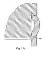
- Fig. 11a and Fig. 11b show further alternatives to the first Process step of a manufacturing method for joining a sealed unit of freewheel outer ring 113 and a Sealing disk 117.
- the recesses 120 of the Freewheel outer ring 113 designed differently than in the Exemplary embodiment according to FIGS. 1 to 9 sharp-edged outer edge 130 not parallel, but angular configured to the central axis of the freewheel outer ring 113, so that forms an acute angle in the depression.
- the Sealing disk 117 has in its edge region a circumferential Beading 150 so that the sealing washer 117 under Pressurization by means of the annular pressure piston 127th in the freewheel outer ring 113 in the area of the pointed Winkels can be pressed sealing.
- the sealing washer of FIG. 11 b is in contrast to Sealing disk 117 of FIG. 11a with a radially inside the Beading arranged annular surface 190 on the freewheel outer ring, so when pressing the sealing washer in the freewheel outer ring an abutment for the pressure piston is created.
- Fig. 12 shows a profile of an alternative freewheel outer ring 213, which in contrast to that of FIG. 2 exclusively one-sided tapered beveled. After forging this Freewheel outer ring 213 remains on one side of a in the drawing dashed line shown 251 about which is then scalegrated. After the following Turning gears, the freewheel outer ring 213 still with a Broach processed and finally hardened.
- Fig. 13 shows a profile of an alternative freewheel outer ring 313, which is essentially by the differently designed Recording for the sealing disc 317 of the Design example according to FIG. 2 different.
- the Freewheel outer ring 351 is on both sides on the outside the center tapers conically. That of the Freewheel outer ring 351 is provided with a Gesenkanzug. After the forging of this freewheel outer ring 313 remains in the Middle a dashed line shown in the drawing degree 351 over, which is then Sawgrated. After the following Turning operations, the freewheel outer ring 313 still with a Broach processed.
- the symmetrical design of the Freewheel outer ring 313 advantageously prevents a wrong insertion of the workpiece during turning.
- the sealing disc 317 is at the radially outer edge region to bent a paragraph of the freewheel outer ring.
- a Clip connection or a flange be provided.
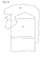
- FIGS. 14 to 16 show different ones Embodiments of the connection between the freewheel outer ring and stator in the area in which the thrust washer is used. These embodiments have a Exposure 490 or 590 or 690 to pouring To get around problems.
- FIG. 16 next to the annular groove 663 in the freewheel outer ring 613 a wedge-shaped annular groove 665 with a pointed groove base, which is between freewheel outer ring 613 and stator 606 forms.
- the Outer diameter of the wedge-shaped annular groove 665 is smaller than the outer diameter of the thrust washer, so this Thrust washer when caulking from the stator 606 with the Thrust washer on the existing paragraph 667 of the stator 606 supported.
- Fig. 17 shows in detail the other two-part mold half 76 which was briefly listed in the description of FIG. This is between the left part 77 and the right part 78th the two-part mold half 76 forming toothed profile closes the negative mold for the blades of the blade ring. 9 on.
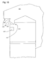
- FIG. 18 shows a partial region of a freewheel outer ring 713 and a sealing washer 717.
- a recess 720 manufacturing technology particularly carried out advantageous.
- the recess 720 has on Well bottom an acute angle within which the annular cavity 721 is located.
- a Centering 722 provided for the sealing disc 717.
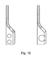
- Fig. 19 shows the inside of two alternatives Sealing washers. These two sealing discs are at the radial inner curved portion circumferentially with punched holes Provided. These six to eight evenly distributed around the circumference Punching holes anchor the gasket better in the cast material of the stator.
- the two alternative sealing washers differ in that the punch holes in one Alternative completely surrounded by the material of the gasket are. In the other alternative, the punch holes exceed the inner edge of the gasket so that the punched holes one have open outer edge.
- sealing washer Sealing ring can be found in other structural configurations extend in another way. They are different shapes the sealing washer / the sealing ring and the joints conceivable. For example, there are various embodiments of Seal / the sealing ring with beads conceivable, where These beads the function of the sealing edges of Fig. 7 take over. That the bent sheet metal of the beads lies on the Mold half under pressure, so no liquid Casting material can flow past this contact surface.
- Fig. 20 shows a profile of an alternative freewheel outer ring 813, which is the freewheel outer ring of FIG. 13 in essential for the differently shaped recording for the Seal 317 different. So is an annular groove 320, in which the sealing disc 317 is formed on a smaller one Diameter, as in the freewheel outer ring of FIG. 13th As a result, the freewheel outer ring 813 is centered Level 800 unbalanced or at its end faces on both sides differently designed. This prevents the principle different in the two directions of rotation effective freewheel outer ring with the wrong side in the Half of the mold according to FIG. 6 and FIG. 7 can be inserted.
- the sealing ring For sealing connection between freewheel outer ring and Sealing ring, the sealing ring alternatively also to the Be glued freewheel outer ring.
- Both the freewheel outer ring and the bearing inner ring of Freewheeling may be in alternative embodiments hardened sintered metal. Also, only one of the Both rings are made of hardened sintered metal.
- the axial and radial bearing sealing disc can, for example be designed similar to a plain bearing bushing, wherein the Federal axially abuts the bearing inner ring of the freewheel, whereas the sleeve of the plain bearing bush radially on the bearing inner ring the freewheel is applied.
- the plain bearing collar can alternatively also radially and / or axially directly opposite to the Be mounted gear shaft. As dependent on the concrete Material in the production of a Kunststoffleitrades none high temperatures may occur this Sliding bearing bushing for the prevention of tension even due to different thermal expansion coefficients also made of plastic.
- the Sealing ring designed as a solid metal part, whose Sliding bearing surfaces are machined surfaces.
- a sealing ring made of cast material or a forged gasket used must, instead of punching a punch hole for cooling and Lubricant supply of the freewheel another Machining form can be selected.
- the unit of sealing ring and Diffuser also be drilled later. Because this hole after making the complete unit circumferentially at each can be arranged anywhere, this hole can also in a particularly advantageous manner for balancing the stator be used.
Landscapes
- Engineering & Computer Science (AREA)
- General Engineering & Computer Science (AREA)
- Mechanical Engineering (AREA)
- Manufacture Of Motors, Generators (AREA)
Applications Claiming Priority (2)
| Application Number | Priority Date | Filing Date | Title |
|---|---|---|---|
| DE10231608 | 2002-07-12 | ||
| DE2002131608 DE10231608A1 (de) | 2002-07-12 | 2002-07-12 | Hydrodynamischer Drehmomentwandler mit einem Leitrad und Herstellungsverfahren für ein solches |
Publications (2)
| Publication Number | Publication Date |
|---|---|
| EP1380771A2 true EP1380771A2 (fr) | 2004-01-14 |
| EP1380771A3 EP1380771A3 (fr) | 2005-12-28 |
Family
ID=29723876
Family Applications (1)
| Application Number | Title | Priority Date | Filing Date |
|---|---|---|---|
| EP03012383A Withdrawn EP1380771A3 (fr) | 2002-07-12 | 2003-05-30 | Convertisseur de couple hydrodynamique avec un stator et son procédé de fabrication |
Country Status (2)
| Country | Link |
|---|---|
| EP (1) | EP1380771A3 (fr) |
| DE (1) | DE10231608A1 (fr) |
Cited By (1)
| Publication number | Priority date | Publication date | Assignee | Title |
|---|---|---|---|---|
| CN106678322A (zh) * | 2017-02-28 | 2017-05-17 | 湖北威能达驱动技术系统有限公司 | 一种液力耦合器叶轮及液力耦合器 |
Families Citing this family (2)
| Publication number | Priority date | Publication date | Assignee | Title |
|---|---|---|---|---|
| DE102004024004B4 (de) * | 2004-05-14 | 2017-01-26 | Daimler Ag | Hydrodynamischer Drehmomentwandler |
| DE102007009092A1 (de) * | 2007-02-24 | 2008-08-28 | Schaeffler Kg | Leitradmodul für einen Drehmomentwandler |
Citations (1)
| Publication number | Priority date | Publication date | Assignee | Title |
|---|---|---|---|---|
| DE19826351C2 (de) | 1998-06-12 | 2001-06-28 | Daimler Chrysler Ag | Antriebsanordnung mit hydrodynamischen Drehmomentwandler und zwei Dämpfern |
Family Cites Families (7)
| Publication number | Priority date | Publication date | Assignee | Title |
|---|---|---|---|---|
| JPH01234652A (ja) * | 1988-03-15 | 1989-09-19 | Japan Autom Transmission Co Ltd | ステータ組立体及びこれの製造方法 |
| US5094076A (en) * | 1990-11-16 | 1992-03-10 | Maclean-Fogg Company | Torque converter reactor assembly and method |
| JPH09152006A (ja) * | 1995-11-30 | 1997-06-10 | Nok Corp | ステータ |
| EP0802037B1 (fr) * | 1996-04-20 | 2001-10-10 | Georg Fischer Mössner GmbH | Pièce composite |
| DE19626974A1 (de) * | 1996-04-20 | 1997-10-23 | Ford Werke Ag | Verbundbauteil |
| FR2756029B1 (fr) * | 1996-11-20 | 1998-12-18 | Skf France | Dispositif de roue libre a flasque de retenue |
| DE10011237C2 (de) * | 2000-03-08 | 2002-09-12 | Borgwarner Inc | Baugruppe mit Freilauf und Leitrad eines hydrodynamischen Wandlers |
-
2002
- 2002-07-12 DE DE2002131608 patent/DE10231608A1/de not_active Withdrawn
-
2003
- 2003-05-30 EP EP03012383A patent/EP1380771A3/fr not_active Withdrawn
Patent Citations (1)
| Publication number | Priority date | Publication date | Assignee | Title |
|---|---|---|---|---|
| DE19826351C2 (de) | 1998-06-12 | 2001-06-28 | Daimler Chrysler Ag | Antriebsanordnung mit hydrodynamischen Drehmomentwandler und zwei Dämpfern |
Cited By (2)
| Publication number | Priority date | Publication date | Assignee | Title |
|---|---|---|---|---|
| CN106678322A (zh) * | 2017-02-28 | 2017-05-17 | 湖北威能达驱动技术系统有限公司 | 一种液力耦合器叶轮及液力耦合器 |
| CN106678322B (zh) * | 2017-02-28 | 2023-10-03 | 湖北威能达驱动技术系统有限公司 | 一种液力耦合器叶轮及液力耦合器 |
Also Published As
| Publication number | Publication date |
|---|---|
| DE10231608A1 (de) | 2004-01-29 |
| EP1380771A3 (fr) | 2005-12-28 |
Similar Documents
| Publication | Publication Date | Title |
|---|---|---|
| DE69715113T2 (de) | Synchronring für eine Getriebe-Synchronisiereinrichtung | |
| DE19843946A1 (de) | Riemenscheibeneinheit | |
| WO2015007359A1 (fr) | Transmission pourvue d'une première et d'une deuxième parties de carter | |
| DE3140373A1 (de) | Radlagereinheit fuer angetriebene raeder von kraftfahrzeugen | |
| WO2015090297A1 (fr) | Centrage d'arbre à cames dans le rotor divisé d'un déphaseur d'arbre à cames hydraulique | |
| DE10156041A1 (de) | Hydrodynamische Kopplungseinrichtung | |
| EP1704339A1 (fr) | Chemin de roulement exterieur d'un roulement de roue et fixation axiale du roulement exterieur | |
| DE60102885T2 (de) | Verschleissbeständige Kraftstoffpumpe | |
| DE102006027494A1 (de) | Welle mit fixiertem Bauteil | |
| DE19645174B4 (de) | Schwungmassenvorrichtung mit einer Gleitlagerung | |
| DE10129709A1 (de) | Radlagereinheit, bestehend aus Wälzlagerung und Gleichlaufgelenk | |
| EP1380771A2 (fr) | Convertisseur de couple hydrodynamique avec un stator et son procédé de fabrication | |
| DE19780552B4 (de) | Hydrodynamischer Momentwandler, insbesondere für Kraftfahrzeuge | |
| DE10153432C1 (de) | Wälzlager und Verfahren zur Befestigung eines Wälzlagers | |
| DE10247668A1 (de) | Vakuumpumpe | |
| EP0802037B1 (fr) | Pièce composite | |
| DE1286840B (de) | Turbinen- bzw. Pumpenrad fuer eine hydrodynamische Einheit, insbesondere fuer eine hydrodynamische Kupplung bei Kraftfahrzeugen | |
| DE4300869B4 (de) | Drehschwingungsdämpfer, insbesondere für Kraftfahrzeuge | |
| DE102014200818A1 (de) | Zweigeteilter Stator mit kaltverschweißtem Deckel | |
| EP2025959B1 (fr) | Elément de machines pour une liaison arbre-moyeu et procédé de fabrication d'une liaison arbre-moyeu | |
| DE102009013964B4 (de) | Bremsscheibe | |
| DE69401628T2 (de) | Anker - Zusammenbau einer elektromagnetischen Kupplung anpassungsfähig an verscheidene Arten von Naben | |
| CH694992A5 (de) | Stuetzscheibe. | |
| DE60128280T2 (de) | Hydrodynamischer Drehmomentwandler mit Freilaufkupplung und Stator | |
| DE102005014916A1 (de) | Radiallagerung für eine Antriebswelle von Fahrzeugen |
Legal Events
| Date | Code | Title | Description |
|---|---|---|---|
| PUAI | Public reference made under article 153(3) epc to a published international application that has entered the european phase |
Free format text: ORIGINAL CODE: 0009012 |
|
| AK | Designated contracting states |
Kind code of ref document: A2 Designated state(s): AT BE BG CH CY CZ DE DK EE ES FI FR GB GR HU IE IT LI LU MC NL PT RO SE SI SK TR |
|
| AX | Request for extension of the european patent |
Extension state: AL LT LV MK |
|
| PUAL | Search report despatched |
Free format text: ORIGINAL CODE: 0009013 |
|
| AK | Designated contracting states |
Kind code of ref document: A3 Designated state(s): AT BE BG CH CY CZ DE DK EE ES FI FR GB GR HU IE IT LI LU MC NL PT RO SE SI SK TR |
|
| AX | Request for extension of the european patent |
Extension state: AL LT LV MK |
|
| AKX | Designation fees paid | ||
| STAA | Information on the status of an ep patent application or granted ep patent |
Free format text: STATUS: THE APPLICATION IS DEEMED TO BE WITHDRAWN |
|
| 18D | Application deemed to be withdrawn |
Effective date: 20060629 |
|
| REG | Reference to a national code |
Ref country code: DE Ref legal event code: 8566 |