EP1380962B1 - Appareil et méthode pour la communication de données - Google Patents
Appareil et méthode pour la communication de données Download PDFInfo
- Publication number
- EP1380962B1 EP1380962B1 EP03012976A EP03012976A EP1380962B1 EP 1380962 B1 EP1380962 B1 EP 1380962B1 EP 03012976 A EP03012976 A EP 03012976A EP 03012976 A EP03012976 A EP 03012976A EP 1380962 B1 EP1380962 B1 EP 1380962B1
- Authority
- EP
- European Patent Office
- Prior art keywords
- data
- arbitration
- host
- bus
- data bus
- Prior art date
- Legal status (The legal status is an assumption and is not a legal conclusion. Google has not performed a legal analysis and makes no representation as to the accuracy of the status listed.)
- Expired - Lifetime
Links
Images


Classifications
-
- G—PHYSICS
- G06—COMPUTING OR CALCULATING; COUNTING
- G06F—ELECTRIC DIGITAL DATA PROCESSING
- G06F15/00—Digital computers in general; Data processing equipment in general
- G06F15/16—Combinations of two or more digital computers each having at least an arithmetic unit, a program unit and a register, e.g. for a simultaneous processing of several programs
- G06F15/163—Interprocessor communication
- G06F15/17—Interprocessor communication using an input/output type connection, e.g. channel, I/O port
Definitions
- the invention relates to an apparatus and a method for data communication between a first host device or another host device and at least one client device along a common transmission path.
- a host device may be a host computer (personal computer, workstation), and a client device may be any hardware application (eg, FPGA or ASIC).
- Fig. 3 shows a communication system of the applicant of the present application, which is known under the brand UMRBus.
- This communication system allows easy transfer of data and / or signals between a host device or host computer (300) and associated hardware (clients), such as ASICs or FPGAs.
- clients such as ASICs or FPGAs.
- Different software applications may communicate with their respective hardware applications via independent virtual channels using the same hardware interface between the host computer (300) and the client hardware (331, 332, 333).
- This communication system presents a simple standardized interface between the host computer (300) and at least one client (331, 332, 333).
- This client (331, 332, 333) can be both a software application and a hardware application.
- HAPP Host Application
- host application interface ie a host application interface (310)
- HPIM host application interface module
- the host application is a program that communicates with one or more client application (s) via the host application interface.
- the Host Application Interface Module (312) is a software library that provides a variety of functions and commands for accessing the communication system.
- a host application interface HAPI is an interface on which to set up host applications.
- the host application interface module (312) is directly connected to a software interface module "SIM", that is to say a software interface unit (314), which generally corresponds to the operating-system-specific device driver.
- SIM software interface module
- a host application interface unit HAPIM provides the host application interface and, in cooperation with the software interface unit, transmits data to and from the clients.
- the Software Interface Module (314) communicates with a Hardware Interface Module (HIM) (318) via a standard interface connection (316), such as PCI or RS232.
- the hardware interface module (318) represents the remote station to the software interface module (314) in hardware.
- This hardware interface module (318) can, for example, be a PCI controller and an interface component between the PCI controller and a data bus.
- the software interface unit SIM performs the data exchange between the host application interface unit HAPIM and the hardware interface unit HIM.
- An essential feature of the hardware interface module (318) is that it always provides a physical data bus (320) on the side away from the software.
- This data bus (320) connects the hardware interface module (318) to a plurality of client application interface modules "CAPIM", also called client application interface units (341, 342, 343).
- client application interface modules "CAPIM", also called client application interface units (341, 342, 343).
- the data bus (320) represents a ring connection between the client application interface units (341, 342, 343) and the hardware interface module (318) incorporated therein.
- the hardware interface unit HIM exchanges data with the software interface unit SIM and makes the data bus available to the clients.
- Each client application interface module (341, 342, 343) represents a type of node inserted in the physical data bus (320).
- Each client application interface module (341, 342, 343) is via a client application interface "CAPI”, also called client application interface (322), with a client application "CAPP”, ie a client application (351, 352 , 353), in connection.
- Each client application interface module (341, 342, 343) has its own address and a type identifier and makes the client application interface (322) available to the client application (351, 352, 353).
- the entire data communication is controlled by the host computer (300).
- Data exchange can take place only between a hardware interface module (318) and in each case a client application interface module (341, 342, 343).
- a hardware interface module (318) and in each case a client application interface module (341, 342, 343).
- client application interface module (341, 342, 343) a hardware interface module
- the host computer (300) and the client applications (351, 352, 353) are possible, but not within the client applications (351, 352, 353) embodied as hardware in the example shown.
- this known device for data communication can not be used in systems with multiple host computers.
- the US 5,687,320 A discloses a device for data communication between a first host device or another host device and at least one client device along a transmission path designed as a ring bus. A separate bus control module is not provided. It should be noted that there is no guarantee that no message collisions occur on the bus when transmitting UDP messages. For this reason, such messages are sent only on subordinate subnets.
- the EP 0 165 185 A1 relates to a method and apparatus for transferring data between multiple interconnected stations.
- the stations permanently listen to the transmission path to check the activity on the shared bus. If too much time has passed without activity on the bus, it is considered that the token running on the bus has been lost. If so, all stations connected to the bus will simultaneously try to regenerate the token, but only one station will have the right to put a new token into circulation. Thus, in this method, all stations connected to the bus are in competition to create the new token and acquire the right to send that token. Except for that station, which eventually gets the right to send out the new token, all other stations are in vain to regenerate the lost token.
- the object of the present invention is to provide a device for data communication between a first host device or another host device and at least one client device along a common transmission path as well as a corresponding method for data communication, where possible blockages of the transmission path to efficient Way and reliably be reversed automatically.
- this device With this device according to the invention, data communication on a common transmission path is made possible even if several host devices are provided.
- this device can be used within FPGA-based image processing systems to control the image processing implemented in the FPGA, even if the image processing system has its own integrated processor, ie its own host device, which uses parameters parallel to the parent host device Want to change data bus.
- the transmission control unit in the device according to the invention assumes the task of controlling which of the host device may use the transmission path in a certain period or for a certain amount of data.
- the provided in the inventive device bus control module takes over as a transmission control unit, the task of controlling and controlling the traffic on the data bus and permanently checks the presence of circulating on the data bus arbitration frames. Represents that Bus control module determines that the bus is blocked by timeout of the interval between two arbitration frames, so a new arbitration frame is automatically generated by the data bus control module and sent to the bus, thereby releasing this again.
- the first and / or the further host device in particular the host application, preferably have a processor.
- An essential feature of this method according to the invention is the provision and transmission of arbitration information on the transmission path along the opened communication connection, wherein the arbitration information ensures that only one host device always receives access to the transmission path. In the case of a blockade of the data bus, it is automatically released again. This is done by monitoring the data bus by a bus control module such that the clocks between two passes of the arbitration frame are counted, with a new arbitration frame with the activity bit disabled being transmitted by the bus control module when the number of counted clocks exceeds a predetermined value.
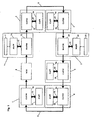
- the Fig. 1 shows a device for data communication according to the present invention with two host devices 1, 2.
- the first host device 1, for example, has a Personal computer (PC) 11 and the second host device 2, for example, has a built-in hardware application processor (embedded processor) 21.
- Such an integrated processor hardware application may be, for example, an ASIC or an FPGA with an integrated processor.
- FPGAs are used in image processing systems. For example, parameters for a frame grabber are transferred from the first host computer to the FPGA hardware that has the integrated processor.
- Both the first host computer 1 and the second host computer 2 are each provided with a master application “MAPP” 14, 24, which is connected via a main application interface unit “MAPIM” (Master Application Interface Module ) is integrated in a data bus 9.
- MAPP master application
- MAPIM Master Application Interface Module
- the main application 14, 24 in this example is a hardware implemented application connected to the main application interface unit 10, 20 via a master application interface (MAPI) 12, 22 and via this is in communication with the data bus 9.
- MAMI master application interface
- client devices 3, 4, 5, 6, 7 which each have a client application "CAPP” (client application) 34, 44, 54, 64, 74.
- Client application interfaces with a client application interface ("CAPI") 32, 42, 52, 62, 72 with a client application interface module ("CAPIM”) 30, 40, 50 , 60, 70 in connection, which in each case is integrated into the data bus 9.
- CAPI client application interface
- CAPIM client application interface module
- a client application here is an application implemented in hardware which exchanges data via the client application interface 32, 42, 52, 62, 72 via the data bus 9 with one of the host computers 1, 2. This data exchange is controlled by the corresponding main application 14, 24.
- the client application interface unit 30, 40, 50, 60, 70 respectively form the interface between the data bus 9 and the respective client application interface 32, 42, 52, 62, 72.
- the respective one via this client application Interface 32, 42, 52, 62, 72 connected to the data bus 9 client 3, 4, 5, 6, 7 or on this running client application 34, 44, 54, 64, 74 are only those data and Services related to the respective client application 34, 44, 54, 64, 74.
- a transfer control unit “BCM” (BUS Control Module) 8 is further integrated, which manages the access of the individual main application interface devices 10, 20 to the data bus 9 and the data bus interrupts supervised.
- the hardware interface unit HIM is not as in the prior art Fig. 3 integrated directly into the data bus, but provides the data on the data bus 9 via the main application interface unit 10, 20.
- the hardware interface unit HIM can be formed by the respective main application MAPP 14, 24.
- Fig. 2 The following describes access management of a host device to a client device.
- the transmission control unit BCM 8 sends an arbitration information that is constantly available on the data bus 9.
- This arbitration information is embodied, for example, as an arbitration frame which contains a header information and a data word.
- a host computer wants to access the data bus and transmit data via this data to a client application or exchange it with it, in step 101 it issues this access request to the main application interface unit MAPIM assigned to it.
- the main application interface unit MAPIM then adopts the arbitration frame circulated on the data bus 9 in step 102 and reads out the arbitration data therefrom in step 103. Included in the arbitration data is an activity bit indicating whether the data bus 9 is currently being used by another application. If this activity bit is not set, this means that the data bus 9 is free.
- step 104 the main application interface unit MAPIM now checks whether the activity bit is set or not. If the activity bit is set, that is to say the data bus is not free, the MAPIM transfers the arbitration frame back to the data bus in step 105 and takes it over again after a waiting interval 106 in order to repeat steps 102 to 104.
- step 104 if it is determined in step 104 that the activity bit is not set, that is, the data bus is free, the main application interface unit MAPIM in turn sets the activity bit in step 107, indicating that it wants to access the data bus 9.
- the arbitration frame is then transferred back to the data bus 9 in step 108 and continues to run there until he to Transfer controller BCM 8 arrives. This takes over the arbitration block in step 109, reads out the arbitration data in step 110 and, in step 111, reserves the data bus 9 for the requesting host computer.
- a main application interface unit MAPIM may thus use the data bus only if it receives the arbitration frame and in which the activity bit has not already been set by another main application interface unit.
- the arbitration frame is received by the transfer controller BCM and not returned to the data bus when the activity bit is set.
- the main application interface unit MAPIM which has set the activity bit, can now transmit its data via the data bus 9.
- the main application interface unit MAPIM Upon completion of this enabled data communication over the data bus 9, or upon expiration of the predetermined time interval or volume of data transmission, the main application interface unit MAPIM resends the arbitration frame, but now with the activity bit disabled, indicating that the data bus 9 is now free again. In this way it is ensured that only one main application interface unit MAPIM is active on the data bus 9 and there is no overlapping of data transmissions on the data bus.
- the transmission control device BCM 8 monitors the data bus 9 in such a way that it counts the clocks between the passage of two arbitration frames by means of a counter. If the counter value exceeds the predetermined limit of the number of cycles per access, it is concluded that no arbitration frame has been received. This can be done for example by interrupting the data bus 9 or by resetting the entire device. In In this case, the monitoring controller 8 again sends an arbitration frame with the activity bit disabled and thus automatically releases the blocked data bus 9 again.
- the transfer controller BCM 8 takes over the data bus 9 and sends an interrupt frame. If the interrupt frame has been transmitted successfully, the transmission controller BCM 8 sends a so-called "interrupt information frame".
- This "interrupt information frame” informs the main application interface unit MAPIM about the interrupt status of the individual client application interface units CAPIM and can forward this information to the respective main application MAPP for further processing. This ensures that all host computers are informed about interrupts.
- an inventive device for data communication is provided with a data communication method running thereon with a multimaster-capable data bus 9.
- the device according to the invention may also assume other than the above-described embodiments.
- the device may in particular have features that represent a combination of the respective individual features of the claims.
Landscapes
- Engineering & Computer Science (AREA)
- Computer Hardware Design (AREA)
- Theoretical Computer Science (AREA)
- Software Systems (AREA)
- Physics & Mathematics (AREA)
- General Engineering & Computer Science (AREA)
- General Physics & Mathematics (AREA)
- Computer And Data Communications (AREA)
- Bus Control (AREA)
- Multi Processors (AREA)
Claims (9)
- Appareil pour la communication de données entre un premier dispositif hôte ou un autre dispositif hôte et au moins un dispositif client le long d'une voie de transmission commune, l'appareil comprenant les éléments suivants :- un premier dispositif hôte (1) qui inclut une application hôte (11) ;- au moins un autre dispositif hôte (2) qui inclut une application hôte (21) ;- au moins un dispositif client (3, 4, 5, 6, 7), qui inclut une application hôte (34, 44, 54, 64, 74) ;- un module de commande de bus (8) ;- dans lequel les dispositifs hôtes (1, 2) comportent chacun un module interface d'application principale (10, 20), qui est intégré dans la voie de transmission (9) ;- dans lequel les dispositifs hôtes (1, 2) comportent chacun un module d'application principale (14, 24), qui relie l'application hôte respective (11, 21) avec le module interface d'application principale (10, 20) ;- dans lequel chaque dispositif client (3, 4, 5, 6, 7) comprend un module interface d'application client (30, 40, 50, 60, 70) qui est intégré dans la voie de transmission (9) et qui est relié à l'application client associée (34, 44, 54, 64, 74) ;- dans lequel la voie de transmission (9) est mise en oeuvre sous forme de bus de données qui forme une liaison circulaire ;- dans lequel le module interface d'application principale (10, 20) concerné de chaque dispositif hôte (1, 2) et le module interface d'application client (30, 40, 50, 60, 70) correspondant de chaque dispositif client (3, 4, 5, 6, 7) sont reliés l'un à l'autre par le bus de données pour l'échange de données et/ou de signaux ;- dans lequel le module de commande de bus (8) est mis en oeuvre afin de commander l'accès des dispositifs hôtes (1, 2) au bus de données ;- dans lequel le module de commande de bus (8) est prévu dans la structure circulaire du bus de données et est relié au module interface d'application principale (10, 20) correspondant de chaque dispositif hôte (1, 2) et au module interface d'application client correspondant de chaque dispositif client (3, 4, 5, 6, 7) au moyen du bus de données pour l'échange de données et/ou de signaux les uns avec les autres le long d'une liaison de communication ouverte ; et- dans lequel le module de commande de bus (8) est doté d'un compteur qui compte les cycles entre les passages de deux trames d'arbitrage qui contiennent les informations d'arbitrage et qui sont véhiculées vers le bus de données,- dans lequel les informations d'arbitrage contiennent des données au moyen desquelles le bus de données est réservé pour un intervalle temporel prédéterminé ou pour un volume de données prédéterminé pour une transmission de données successive vers le bus de données le long de la liaison de communication ouverte, et- dans lequel le module de commande de bus (8) est réalisé de telle façon que, dans le cas où le nombre des cycles comptés dépasse une valeur prédéterminée, il émet une nouvelle trame d'arbitrage, afin de libérer ainsi à nouveau un bus de données bloqué.
- Appareil selon la revendication 1,
caractérisé en ce que- le module de commande de bus (8) est pourvu d'un comparateur qui compare le nombre de cycles passés entre les deux trames d'arbitrage avec un nombre cible prédéterminé de cycles, et- en ce que le module de commande de bus (8) émet, lorsque le nombre des cycles passés dépasse le nombre cible prédéterminé, une nouvelle trame d'arbitrage avec un bit d'activité désactivé, afin de libérer à nouveau le bus de données bloqué. - Appareil selon la revendication 1 ou 2,
caractérisé en ce que les applications hôtes (11, 21) du premier et/ou du second dispositif hôte (1, 2) comprennent un processeur. - Procédé pour la communication de données dans un appareil pour la communication de données selon la revendication 1, 2 ou 3 entre un premier dispositif hôte (1) ou un autre dispositif hôte (2) et au moins un dispositif client (3, 4, 5, 6, 7) le long d'une voie de transmission commune (9) conçue comme un bus de données formant une liaison circulaire, ledit procédé comprenant les étapes suivantes :- ouverture d'une liaison de communication entre une application hôte en cours sur le dispositif hôte et une application client en cours sur le dispositif client ;- transmission d'informations d'arbitrage sur le bus de données le long de la liaison de communication ouverte, de sorte que les informations d'arbitrage contiennent des données au moyen desquelles le bus de données est réservé pour un intervalle temporel prédéterminé ou pour un volume de données prédéterminé pour une transmission de données successive vers le bus de données le long de la liaison de communication ouverte ;- transmission de données et/ou de signaux entre l'application hôte et l'application client et/ou entre l'application client et l'application hôte sur le bus de données le long de la liaison de communication ouverte ;- dans lequel le passage d'une trame d'arbitrage, contenant les informations d'arbitrage, sur le bus de données est surveillé par un module de commande de bus de telle façon que les cycles entre deux passages de la trame d'arbitrage sont comptés, et- dans lequel une nouvelle trame d'arbitrage avec un bit d'activité désactivé est émise par le module de commande de bus quand le nombre des cycles comptés dépasse une valeur prédéterminée, afin de libérer ainsi à nouveau un bus de données bloqué.
- Procédé selon la revendication 4,
caractérisé en ce que les informations d'arbitrage sont transmises sous forme d'un bloc d'arbitrage, et un bloc d'arbitrage contient des données d'arbitrage qui incluent des informations sur la longueur de l'intervalle temporel prédéterminé ou sur l'étendue du volume de données prédéterminé pour la transmission de données successive. - Procédé selon la revendication 5,
caractérisé en ce que le bloc d'arbitrage comprend des données d'activité qui incluent des informations sur la situation actuelle de la voie de transmission, à partir desquelles il est possible de conclure quant à savoir si la voie de communication est actuellement utilisée pour la transmission de données. - Procédé selon la revendication 4,
caractérisé en ce que lors d'une demande d'accès d'une application hôte vers la voie de transmission, on exécute les étapes suivantes :- le module interface d'application principale associé à l'application hôte reprend le bloc d'arbitrage présent sur la voie de transmission,- il lit les données d'activité,- il vérifie au moyen des données d'activité si la voie de transmission est actuellement libre pour la transmission de données,- si la voie de transmission est libre, il écrit des données d'activité dans le bloc d'arbitrage, qui indiquent une utilisation de la voie de transmission par l'application hôte, et- il remet le bloc d'arbitrage via la voie de transmission au module de commande de bus ;- suite à quoi le module de commande de bus réserve la voie de transmission pour l'accès par l'application hôte. - Procédé selon la revendication 7,
caractérisé en ce que, après la fin d'une transmission de données les données d'activité sont à nouveau remises à zéro dans le bloc d'arbitrage par le module interface d'application principale, et ainsi la voie de transmission est à nouveau libérée. - Procédé selon la revendication 4,
caractérisé en ce que les informations d'arbitrage sont prévues dans un bloc d'arbitrage.
Applications Claiming Priority (2)
| Application Number | Priority Date | Filing Date | Title |
|---|---|---|---|
| DE10231424A DE10231424B4 (de) | 2002-07-11 | 2002-07-11 | Vorrichtung und Verfahren zur Datenkommunikation |
| DE10231424 | 2002-07-11 |
Publications (3)
| Publication Number | Publication Date |
|---|---|
| EP1380962A2 EP1380962A2 (fr) | 2004-01-14 |
| EP1380962A3 EP1380962A3 (fr) | 2005-10-05 |
| EP1380962B1 true EP1380962B1 (fr) | 2012-04-25 |
Family
ID=29723854
Family Applications (1)
| Application Number | Title | Priority Date | Filing Date |
|---|---|---|---|
| EP03012976A Expired - Lifetime EP1380962B1 (fr) | 2002-07-11 | 2003-06-07 | Appareil et méthode pour la communication de données |
Country Status (4)
| Country | Link |
|---|---|
| US (1) | US7441059B2 (fr) |
| EP (1) | EP1380962B1 (fr) |
| AT (1) | ATE555444T1 (fr) |
| DE (1) | DE10231424B4 (fr) |
Families Citing this family (2)
| Publication number | Priority date | Publication date | Assignee | Title |
|---|---|---|---|---|
| US9081743B2 (en) | 2012-05-25 | 2015-07-14 | Pro Design Electronic Gmbh | Communication system and communicaton method |
| EP3634867A4 (fr) * | 2017-06-05 | 2020-12-30 | Bemis Company, Inc. | Emballages refermables souples |
Citations (2)
| Publication number | Priority date | Publication date | Assignee | Title |
|---|---|---|---|---|
| EP0165185A1 (fr) * | 1984-05-22 | 1985-12-18 | Merlin Gerin | Procédé et système de transmission de messages entre plusieurs stations d'un réseau local industriel décentralisé à protocole d'accès déterministe par circulation de jeton |
| US5687320A (en) * | 1995-04-27 | 1997-11-11 | Hewlett-Packard Company | Indirect method for network peripheral automated detection |
Family Cites Families (26)
| Publication number | Priority date | Publication date | Assignee | Title |
|---|---|---|---|---|
| US4646232A (en) * | 1984-01-03 | 1987-02-24 | Texas Instruments Incorporated | Microprocessor with integrated CPU, RAM, timer, bus arbiter data for communication system |
| DE3583177D1 (de) * | 1984-05-04 | 1991-07-18 | Siemens Ag | Verfahren und schaltungsanordnung zum herstellen von verbindungen und uebertragen von nachrichtensignalen zwischen teilnehmerstellen bzw. leitungsanschlussgruppen in einer eine ringleitungsanordnung aufweisenden fernmeldevermittlungsanlage, insbesondere einer datenvermittlungsanlage. |
| NL8500462A (nl) * | 1985-02-19 | 1986-09-16 | Philips Nv | Inrichting voor het overdragen van digitale data. |
| US6041365A (en) * | 1985-10-29 | 2000-03-21 | Kleinerman; Aurel | Apparatus and method for high performance remote application gateway servers |
| US4972313A (en) * | 1989-08-07 | 1990-11-20 | Bull Hn Information Systems Inc. | Bus access control for a multi-host system using successively decremented arbitration delay periods to allocate bus access among the hosts |
| US5555425A (en) * | 1990-03-07 | 1996-09-10 | Dell Usa, L.P. | Multi-master bus arbitration system in which the address and data lines of the bus may be separately granted to individual masters |
| JP2557192B2 (ja) * | 1993-03-15 | 1996-11-27 | インターナショナル・ビジネス・マシーンズ・コーポレイション | トランザクション処理の同期方法、トランザクション処理のモニタ方法及びトランザクションのコミット処理方法 |
| US5457683A (en) * | 1993-05-07 | 1995-10-10 | Apple Computer, Inc. | Link and discovery protocols for a ring interconnect architecture |
| US6381595B1 (en) * | 1994-09-29 | 2002-04-30 | International Business Machines Corporation | System and method for compensation of functional differences between heterogeneous database management systems |
| JPH09200239A (ja) * | 1996-01-19 | 1997-07-31 | Hitachi Ltd | リング接続を用いたデータ転送方法及び情報処理システム |
| US6094532A (en) * | 1997-03-25 | 2000-07-25 | Sun Microsystems, Inc. | Multiprocessor distributed memory system and board and methods therefor |
| US6253292B1 (en) * | 1997-08-22 | 2001-06-26 | Seong Tae Jhang | Distributed shared memory multiprocessor system based on a unidirectional ring bus using a snooping scheme |
| US6138180A (en) * | 1997-09-12 | 2000-10-24 | Symbol Technologies, Inc. | Adaptive computer peripheral for selecting a communications protocol by cycling through a plurality of given protocols |
| US6407983B1 (en) * | 1998-02-20 | 2002-06-18 | Adc Telecommunications, Inc. | Circuit and method for shaping traffic in a virtual connection network |
| US6748473B1 (en) * | 1998-10-30 | 2004-06-08 | Avocent Huntsville Corporation | Split computer system including transmission of video data between plural enclosures |
| US6748419B2 (en) * | 1998-11-25 | 2004-06-08 | Alibre, Inc. | System and method for solid modeling |
| JP3589058B2 (ja) * | 1998-12-25 | 2004-11-17 | 富士ゼロックス株式会社 | 信号通信装置および多重バス制御装置 |
| DE19905841A1 (de) * | 1999-02-12 | 2000-08-24 | Kuka Roboter Gmbh | Vorrichtung zum Verarbeiten sicherheitsrelevanter Daten |
| US6820158B1 (en) * | 1999-08-30 | 2004-11-16 | Intel Corporation | Method and apparatus for a configuration ring |
| US7046665B1 (en) * | 1999-10-26 | 2006-05-16 | Extreme Networks, Inc. | Provisional IP-aware virtual paths over networks |
| JP3417369B2 (ja) * | 1999-11-05 | 2003-06-16 | 日本電気株式会社 | バススイッチ用アダプタ、バススイッチ用ブリッジ、バススイッチ、およびバススイッチシステム |
| JP4039794B2 (ja) * | 2000-08-18 | 2008-01-30 | 富士通株式会社 | マルチパス計算機システム |
| JP3789295B2 (ja) * | 2000-11-02 | 2006-06-21 | 富士通株式会社 | メッセージ伝達方法と装置 |
| US7139267B2 (en) * | 2002-03-05 | 2006-11-21 | Industrial Technology Research Institute | System and method of stacking network switches |
| US20030025729A1 (en) * | 2001-07-26 | 2003-02-06 | Autodesk, Inc. | Method and apparatus for viewing and marking up a design document |
| US7043579B2 (en) * | 2002-12-05 | 2006-05-09 | International Business Machines Corporation | Ring-topology based multiprocessor data access bus |
-
2002
- 2002-07-11 DE DE10231424A patent/DE10231424B4/de not_active Expired - Lifetime
-
2003
- 2003-06-07 EP EP03012976A patent/EP1380962B1/fr not_active Expired - Lifetime
- 2003-06-07 AT AT03012976T patent/ATE555444T1/de active
- 2003-07-09 US US10/616,764 patent/US7441059B2/en not_active Expired - Lifetime
Patent Citations (2)
| Publication number | Priority date | Publication date | Assignee | Title |
|---|---|---|---|---|
| EP0165185A1 (fr) * | 1984-05-22 | 1985-12-18 | Merlin Gerin | Procédé et système de transmission de messages entre plusieurs stations d'un réseau local industriel décentralisé à protocole d'accès déterministe par circulation de jeton |
| US5687320A (en) * | 1995-04-27 | 1997-11-11 | Hewlett-Packard Company | Indirect method for network peripheral automated detection |
Also Published As
| Publication number | Publication date |
|---|---|
| EP1380962A3 (fr) | 2005-10-05 |
| EP1380962A2 (fr) | 2004-01-14 |
| DE10231424B4 (de) | 2006-11-09 |
| DE10231424A1 (de) | 2004-01-29 |
| US7441059B2 (en) | 2008-10-21 |
| US20040024816A1 (en) | 2004-02-05 |
| ATE555444T1 (de) | 2012-05-15 |
Similar Documents
| Publication | Publication Date | Title |
|---|---|---|
| DE4426123C2 (de) | Arbitrierung bei verzögernder Buskopplung | |
| EP1298849B1 (fr) | Procédé et dispositif de transmission d'information via un système de bus et système de bus | |
| DE69123663T2 (de) | Kanäle in einem Rechnerein-Ausgabesystem | |
| DE3300261C2 (fr) | ||
| EP2622826B1 (fr) | Procédé d'attribution automatique d'adresse à des abonnés de bus de même type | |
| DE3300262C2 (fr) | ||
| DE4129205A1 (de) | Verfahren zum aufbau von botschaften fuer den datenaustausch und/oder fuer die synchronisation von prozessen in datenverarbeitungsanlagen | |
| DE19721740B4 (de) | Steuerungsverfahren für den Medienzugriff bei einem seriellen Bus | |
| WO2002015452A2 (fr) | Procede d'adressage pour au moins un dispositif de bus nouvellement raccorde a un systeme de bus | |
| EP2957074B1 (fr) | Véhicule à moteur équipé d'un bus de communication embarqué et procédé de génération d'informations de bus | |
| EP0570338A1 (fr) | Procédé et dispositif pour la surveillance et la protection d'accès dans les réseaux de communication | |
| DE10127417A1 (de) | Transport-Protokoll für die Gerätekommunikation | |
| EP0509114B1 (fr) | Méthode pour la transmission de données à plusieurs stations | |
| EP1380962B1 (fr) | Appareil et méthode pour la communication de données | |
| EP3669501B1 (fr) | Procédé de préparation de paquets de données à partir d'un bus can ; appareil de commande et système pourvu d'un bus can | |
| EP1497735B1 (fr) | Procede et dispositif d'inspection d'une fonction de surveillance d'un systeme de bus et systeme de bus | |
| EP1642207A1 (fr) | Attribution d'adresses de station a des abonnes de communication dans un systeme de bus | |
| EP0239827A2 (fr) | Méthode de commande d'une mémoire commune d'un système multiprocesseur comprenant des systèmes microprocesseurs séparés | |
| DE19756885B4 (de) | Verfahren zum Austausch von Signalen zwischen über einen Bus verbundenen Modulen sowie Vorrichtung zur Durchführung des Verfahrens | |
| EP1103022B1 (fr) | Procede de communication | |
| EP2741453B1 (fr) | Procédé de fonctionnement d'un appareil bus d'un dispositif d'automatisation du bâtiment, et appareil de configuration et produit programme d'ordinateur correspondants | |
| DE10028370B4 (de) | Verfahren zur Datenkommunikation zwischen mehreren MAC-Steuereinheiten | |
| DE10201319B4 (de) | Verfahren zur Datenübertragung und serielles Bussystem | |
| WO2003081847A1 (fr) | Utilisation d'emplacements sans appartenance pour l'attribution dynamique de largeur de bande | |
| EP0242765A2 (fr) | Méthode et dispositif pour la transmission d'informations dans des systèmes multiordinateurs avec un réseau de transmission hiérarchique |
Legal Events
| Date | Code | Title | Description |
|---|---|---|---|
| PUAI | Public reference made under article 153(3) epc to a published international application that has entered the european phase |
Free format text: ORIGINAL CODE: 0009012 |
|
| AK | Designated contracting states |
Kind code of ref document: A2 Designated state(s): AT BE BG CH CY CZ DE DK EE ES FI FR GB GR HU IE IT LI LU MC NL PT RO SE SI SK TR |
|
| AX | Request for extension of the european patent |
Extension state: AL LT LV MK |
|
| PUAL | Search report despatched |
Free format text: ORIGINAL CODE: 0009013 |
|
| AK | Designated contracting states |
Kind code of ref document: A3 Designated state(s): AT BE BG CH CY CZ DE DK EE ES FI FR GB GR HU IE IT LI LU MC NL PT RO SE SI SK TR |
|
| AX | Request for extension of the european patent |
Extension state: AL LT LV MK |
|
| 17P | Request for examination filed |
Effective date: 20060321 |
|
| AKX | Designation fees paid |
Designated state(s): AT BE BG CH CY CZ DE DK EE ES FI FR GB GR HU IE IT LI LU MC NL PT RO SE SI SK TR |
|
| AXX | Extension fees paid |
Extension state: MK Payment date: 20060321 Extension state: LT Payment date: 20060321 Extension state: AL Payment date: 20060321 Extension state: LV Payment date: 20060321 |
|
| RAP1 | Party data changed (applicant data changed or rights of an application transferred) |
Owner name: PRO DESIGN ELECTRONIC GMBH |
|
| RAP1 | Party data changed (applicant data changed or rights of an application transferred) |
Owner name: SYNOPSYS, INC. |
|
| 17Q | First examination report despatched |
Effective date: 20101221 |
|
| GRAP | Despatch of communication of intention to grant a patent |
Free format text: ORIGINAL CODE: EPIDOSNIGR1 |
|
| GRAS | Grant fee paid |
Free format text: ORIGINAL CODE: EPIDOSNIGR3 |
|
| GRAA | (expected) grant |
Free format text: ORIGINAL CODE: 0009210 |
|
| AK | Designated contracting states |
Kind code of ref document: B1 Designated state(s): AT BE BG CH CY CZ DE DK EE ES FI FR GB GR HU IE IT LI LU MC NL PT RO SE SI SK TR |
|
| AX | Request for extension of the european patent |
Extension state: AL LT LV MK |
|
| REG | Reference to a national code |
Ref country code: GB Ref legal event code: FG4D Free format text: NOT ENGLISH |
|
| REG | Reference to a national code |
Ref country code: CH Ref legal event code: EP |
|
| REG | Reference to a national code |
Ref country code: AT Ref legal event code: REF Ref document number: 555444 Country of ref document: AT Kind code of ref document: T Effective date: 20120515 |
|
| REG | Reference to a national code |
Ref country code: IE Ref legal event code: FG4D Free format text: LANGUAGE OF EP DOCUMENT: GERMAN |
|
| REG | Reference to a national code |
Ref country code: DE Ref legal event code: R096 Ref document number: 50314313 Country of ref document: DE Effective date: 20120614 |
|
| REG | Reference to a national code |
Ref country code: NL Ref legal event code: VDEP Effective date: 20120425 |
|
| LTLA | Lt: lapse of european patent or patent extension | ||
| PG25 | Lapsed in a contracting state [announced via postgrant information from national office to epo] |
Ref country code: CY Free format text: LAPSE BECAUSE OF FAILURE TO SUBMIT A TRANSLATION OF THE DESCRIPTION OR TO PAY THE FEE WITHIN THE PRESCRIBED TIME-LIMIT Effective date: 20120425 Ref country code: FI Free format text: LAPSE BECAUSE OF FAILURE TO SUBMIT A TRANSLATION OF THE DESCRIPTION OR TO PAY THE FEE WITHIN THE PRESCRIBED TIME-LIMIT Effective date: 20120425 Ref country code: SE Free format text: LAPSE BECAUSE OF FAILURE TO SUBMIT A TRANSLATION OF THE DESCRIPTION OR TO PAY THE FEE WITHIN THE PRESCRIBED TIME-LIMIT Effective date: 20120425 |
|
| PG25 | Lapsed in a contracting state [announced via postgrant information from national office to epo] |
Ref country code: PT Free format text: LAPSE BECAUSE OF FAILURE TO SUBMIT A TRANSLATION OF THE DESCRIPTION OR TO PAY THE FEE WITHIN THE PRESCRIBED TIME-LIMIT Effective date: 20120827 Ref country code: GR Free format text: LAPSE BECAUSE OF FAILURE TO SUBMIT A TRANSLATION OF THE DESCRIPTION OR TO PAY THE FEE WITHIN THE PRESCRIBED TIME-LIMIT Effective date: 20120726 Ref country code: SI Free format text: LAPSE BECAUSE OF FAILURE TO SUBMIT A TRANSLATION OF THE DESCRIPTION OR TO PAY THE FEE WITHIN THE PRESCRIBED TIME-LIMIT Effective date: 20120425 |
|
| BERE | Be: lapsed |
Owner name: SYNOPSYS, INC. Effective date: 20120630 |
|
| PG25 | Lapsed in a contracting state [announced via postgrant information from national office to epo] |
Ref country code: SK Free format text: LAPSE BECAUSE OF FAILURE TO SUBMIT A TRANSLATION OF THE DESCRIPTION OR TO PAY THE FEE WITHIN THE PRESCRIBED TIME-LIMIT Effective date: 20120425 Ref country code: EE Free format text: LAPSE BECAUSE OF FAILURE TO SUBMIT A TRANSLATION OF THE DESCRIPTION OR TO PAY THE FEE WITHIN THE PRESCRIBED TIME-LIMIT Effective date: 20120425 Ref country code: MC Free format text: LAPSE BECAUSE OF NON-PAYMENT OF DUE FEES Effective date: 20120630 Ref country code: CZ Free format text: LAPSE BECAUSE OF FAILURE TO SUBMIT A TRANSLATION OF THE DESCRIPTION OR TO PAY THE FEE WITHIN THE PRESCRIBED TIME-LIMIT Effective date: 20120425 Ref country code: DK Free format text: LAPSE BECAUSE OF FAILURE TO SUBMIT A TRANSLATION OF THE DESCRIPTION OR TO PAY THE FEE WITHIN THE PRESCRIBED TIME-LIMIT Effective date: 20120425 Ref country code: RO Free format text: LAPSE BECAUSE OF FAILURE TO SUBMIT A TRANSLATION OF THE DESCRIPTION OR TO PAY THE FEE WITHIN THE PRESCRIBED TIME-LIMIT Effective date: 20120425 Ref country code: NL Free format text: LAPSE BECAUSE OF FAILURE TO SUBMIT A TRANSLATION OF THE DESCRIPTION OR TO PAY THE FEE WITHIN THE PRESCRIBED TIME-LIMIT Effective date: 20120425 |
|
| REG | Reference to a national code |
Ref country code: CH Ref legal event code: PL |
|
| REG | Reference to a national code |
Ref country code: CH Ref legal event code: PL |
|
| PG25 | Lapsed in a contracting state [announced via postgrant information from national office to epo] |
Ref country code: IT Free format text: LAPSE BECAUSE OF FAILURE TO SUBMIT A TRANSLATION OF THE DESCRIPTION OR TO PAY THE FEE WITHIN THE PRESCRIBED TIME-LIMIT Effective date: 20120425 |
|
| PLBE | No opposition filed within time limit |
Free format text: ORIGINAL CODE: 0009261 |
|
| STAA | Information on the status of an ep patent application or granted ep patent |
Free format text: STATUS: NO OPPOSITION FILED WITHIN TIME LIMIT |
|
| REG | Reference to a national code |
Ref country code: IE Ref legal event code: MM4A |
|
| 26N | No opposition filed |
Effective date: 20130128 |
|
| PG25 | Lapsed in a contracting state [announced via postgrant information from national office to epo] |
Ref country code: BE Free format text: LAPSE BECAUSE OF NON-PAYMENT OF DUE FEES Effective date: 20120630 Ref country code: ES Free format text: LAPSE BECAUSE OF FAILURE TO SUBMIT A TRANSLATION OF THE DESCRIPTION OR TO PAY THE FEE WITHIN THE PRESCRIBED TIME-LIMIT Effective date: 20120805 Ref country code: IE Free format text: LAPSE BECAUSE OF NON-PAYMENT OF DUE FEES Effective date: 20120607 Ref country code: CH Free format text: LAPSE BECAUSE OF NON-PAYMENT OF DUE FEES Effective date: 20120630 Ref country code: LI Free format text: LAPSE BECAUSE OF NON-PAYMENT OF DUE FEES Effective date: 20120630 |
|
| REG | Reference to a national code |
Ref country code: DE Ref legal event code: R097 Ref document number: 50314313 Country of ref document: DE Effective date: 20130128 |
|
| PG25 | Lapsed in a contracting state [announced via postgrant information from national office to epo] |
Ref country code: BG Free format text: LAPSE BECAUSE OF FAILURE TO SUBMIT A TRANSLATION OF THE DESCRIPTION OR TO PAY THE FEE WITHIN THE PRESCRIBED TIME-LIMIT Effective date: 20120725 |
|
| REG | Reference to a national code |
Ref country code: AT Ref legal event code: MM01 Ref document number: 555444 Country of ref document: AT Kind code of ref document: T Effective date: 20120607 |
|
| PG25 | Lapsed in a contracting state [announced via postgrant information from national office to epo] |
Ref country code: AT Free format text: LAPSE BECAUSE OF NON-PAYMENT OF DUE FEES Effective date: 20120607 |
|
| PG25 | Lapsed in a contracting state [announced via postgrant information from national office to epo] |
Ref country code: TR Free format text: LAPSE BECAUSE OF FAILURE TO SUBMIT A TRANSLATION OF THE DESCRIPTION OR TO PAY THE FEE WITHIN THE PRESCRIBED TIME-LIMIT Effective date: 20120425 |
|
| PG25 | Lapsed in a contracting state [announced via postgrant information from national office to epo] |
Ref country code: LU Free format text: LAPSE BECAUSE OF NON-PAYMENT OF DUE FEES Effective date: 20120607 |
|
| PG25 | Lapsed in a contracting state [announced via postgrant information from national office to epo] |
Ref country code: HU Free format text: LAPSE BECAUSE OF FAILURE TO SUBMIT A TRANSLATION OF THE DESCRIPTION OR TO PAY THE FEE WITHIN THE PRESCRIBED TIME-LIMIT Effective date: 20030607 |
|
| REG | Reference to a national code |
Ref country code: FR Ref legal event code: PLFP Year of fee payment: 13 |
|
| PGFP | Annual fee paid to national office [announced via postgrant information from national office to epo] |
Ref country code: GB Payment date: 20150603 Year of fee payment: 13 |
|
| REG | Reference to a national code |
Ref country code: FR Ref legal event code: PLFP Year of fee payment: 14 |
|
| GBPC | Gb: european patent ceased through non-payment of renewal fee |
Effective date: 20160607 |
|
| REG | Reference to a national code |
Ref country code: FR Ref legal event code: PLFP Year of fee payment: 15 |
|
| PG25 | Lapsed in a contracting state [announced via postgrant information from national office to epo] |
Ref country code: GB Free format text: LAPSE BECAUSE OF NON-PAYMENT OF DUE FEES Effective date: 20160607 |
|
| REG | Reference to a national code |
Ref country code: FR Ref legal event code: PLFP Year of fee payment: 16 |
|
| PGFP | Annual fee paid to national office [announced via postgrant information from national office to epo] |
Ref country code: FR Payment date: 20220519 Year of fee payment: 20 Ref country code: DE Payment date: 20220518 Year of fee payment: 20 |
|
| REG | Reference to a national code |
Ref country code: DE Ref legal event code: R071 Ref document number: 50314313 Country of ref document: DE |
|
| P01 | Opt-out of the competence of the unified patent court (upc) registered |
Effective date: 20230528 |