EP1382476A1 - Chaine de traction comportant un mecanisme de changement de rapport integre dans une roue et procédé de changement de rapport associé - Google Patents
Chaine de traction comportant un mecanisme de changement de rapport integre dans une roue et procédé de changement de rapport associé Download PDFInfo
- Publication number
- EP1382476A1 EP1382476A1 EP03015773A EP03015773A EP1382476A1 EP 1382476 A1 EP1382476 A1 EP 1382476A1 EP 03015773 A EP03015773 A EP 03015773A EP 03015773 A EP03015773 A EP 03015773A EP 1382476 A1 EP1382476 A1 EP 1382476A1
- Authority
- EP
- European Patent Office
- Prior art keywords
- wheel
- sensor
- gear change
- speed
- wheels
- Prior art date
- Legal status (The legal status is an assumption and is not a legal conclusion. Google has not performed a legal analysis and makes no representation as to the accuracy of the status listed.)
- Granted
Links
- 238000000034 method Methods 0.000 title claims abstract description 20
- 230000007246 mechanism Effects 0.000 title claims description 20
- 230000007935 neutral effect Effects 0.000 claims abstract description 14
- 230000009347 mechanical transmission Effects 0.000 claims abstract description 9
- 230000008859 change Effects 0.000 claims description 55
- 230000000903 blocking effect Effects 0.000 claims description 10
- 230000002441 reversible effect Effects 0.000 claims description 4
- 230000001360 synchronised effect Effects 0.000 claims description 3
- 230000009467 reduction Effects 0.000 abstract description 13
- 241000282472 Canis lupus familiaris Species 0.000 description 17
- 238000004364 calculation method Methods 0.000 description 9
- 230000005540 biological transmission Effects 0.000 description 7
- 230000002159 abnormal effect Effects 0.000 description 5
- 230000001133 acceleration Effects 0.000 description 3
- 230000008901 benefit Effects 0.000 description 3
- 238000010586 diagram Methods 0.000 description 3
- 235000021183 entrée Nutrition 0.000 description 3
- 230000002093 peripheral effect Effects 0.000 description 3
- 230000000712 assembly Effects 0.000 description 2
- 238000000429 assembly Methods 0.000 description 2
- 230000000994 depressogenic effect Effects 0.000 description 1
- 230000000694 effects Effects 0.000 description 1
- 230000000977 initiatory effect Effects 0.000 description 1
- 238000005259 measurement Methods 0.000 description 1
- 210000000056 organ Anatomy 0.000 description 1
- 230000010355 oscillation Effects 0.000 description 1
- 235000001954 papillon Nutrition 0.000 description 1
- 244000229285 papillon Species 0.000 description 1
- 239000000725 suspension Substances 0.000 description 1
- 230000007704 transition Effects 0.000 description 1
Images


Classifications
-
- B—PERFORMING OPERATIONS; TRANSPORTING
- B60—VEHICLES IN GENERAL
- B60L—PROPULSION OF ELECTRICALLY-PROPELLED VEHICLES; SUPPLYING ELECTRIC POWER FOR AUXILIARY EQUIPMENT OF ELECTRICALLY-PROPELLED VEHICLES; ELECTRODYNAMIC BRAKE SYSTEMS FOR VEHICLES IN GENERAL; MAGNETIC SUSPENSION OR LEVITATION FOR VEHICLES; MONITORING OPERATING VARIABLES OF ELECTRICALLY-PROPELLED VEHICLES; ELECTRIC SAFETY DEVICES FOR ELECTRICALLY-PROPELLED VEHICLES
- B60L7/00—Electrodynamic brake systems for vehicles in general
- B60L7/10—Dynamic electric regenerative braking
- B60L7/18—Controlling the braking effect
-
- B—PERFORMING OPERATIONS; TRANSPORTING
- B60—VEHICLES IN GENERAL
- B60K—ARRANGEMENT OR MOUNTING OF PROPULSION UNITS OR OF TRANSMISSIONS IN VEHICLES; ARRANGEMENT OR MOUNTING OF PLURAL DIVERSE PRIME-MOVERS IN VEHICLES; AUXILIARY DRIVES FOR VEHICLES; INSTRUMENTATION OR DASHBOARDS FOR VEHICLES; ARRANGEMENTS IN CONNECTION WITH COOLING, AIR INTAKE, GAS EXHAUST OR FUEL SUPPLY OF PROPULSION UNITS IN VEHICLES
- B60K17/00—Arrangement or mounting of transmissions in vehicles
- B60K17/04—Arrangement or mounting of transmissions in vehicles characterised by arrangement, location or kind of gearing
- B60K17/043—Transmission unit disposed in on near the vehicle wheel, or between the differential gear unit and the wheel
-
- B—PERFORMING OPERATIONS; TRANSPORTING
- B60—VEHICLES IN GENERAL
- B60K—ARRANGEMENT OR MOUNTING OF PROPULSION UNITS OR OF TRANSMISSIONS IN VEHICLES; ARRANGEMENT OR MOUNTING OF PLURAL DIVERSE PRIME-MOVERS IN VEHICLES; AUXILIARY DRIVES FOR VEHICLES; INSTRUMENTATION OR DASHBOARDS FOR VEHICLES; ARRANGEMENTS IN CONNECTION WITH COOLING, AIR INTAKE, GAS EXHAUST OR FUEL SUPPLY OF PROPULSION UNITS IN VEHICLES
- B60K17/00—Arrangement or mounting of transmissions in vehicles
- B60K17/04—Arrangement or mounting of transmissions in vehicles characterised by arrangement, location or kind of gearing
- B60K17/06—Arrangement or mounting of transmissions in vehicles characterised by arrangement, location or kind of gearing of change-speed gearing
- B60K17/08—Arrangement or mounting of transmissions in vehicles characterised by arrangement, location or kind of gearing of change-speed gearing of mechanical type
-
- B—PERFORMING OPERATIONS; TRANSPORTING
- B60—VEHICLES IN GENERAL
- B60K—ARRANGEMENT OR MOUNTING OF PROPULSION UNITS OR OF TRANSMISSIONS IN VEHICLES; ARRANGEMENT OR MOUNTING OF PLURAL DIVERSE PRIME-MOVERS IN VEHICLES; AUXILIARY DRIVES FOR VEHICLES; INSTRUMENTATION OR DASHBOARDS FOR VEHICLES; ARRANGEMENTS IN CONNECTION WITH COOLING, AIR INTAKE, GAS EXHAUST OR FUEL SUPPLY OF PROPULSION UNITS IN VEHICLES
- B60K7/00—Disposition of motor in, or adjacent to, traction wheel
- B60K7/0007—Disposition of motor in, or adjacent to, traction wheel the motor being electric
-
- B—PERFORMING OPERATIONS; TRANSPORTING
- B60—VEHICLES IN GENERAL
- B60L—PROPULSION OF ELECTRICALLY-PROPELLED VEHICLES; SUPPLYING ELECTRIC POWER FOR AUXILIARY EQUIPMENT OF ELECTRICALLY-PROPELLED VEHICLES; ELECTRODYNAMIC BRAKE SYSTEMS FOR VEHICLES IN GENERAL; MAGNETIC SUSPENSION OR LEVITATION FOR VEHICLES; MONITORING OPERATING VARIABLES OF ELECTRICALLY-PROPELLED VEHICLES; ELECTRIC SAFETY DEVICES FOR ELECTRICALLY-PROPELLED VEHICLES
- B60L7/00—Electrodynamic brake systems for vehicles in general
- B60L7/02—Dynamic electric resistor braking
- B60L7/08—Controlling the braking effect
-
- F—MECHANICAL ENGINEERING; LIGHTING; HEATING; WEAPONS; BLASTING
- F16—ENGINEERING ELEMENTS AND UNITS; GENERAL MEASURES FOR PRODUCING AND MAINTAINING EFFECTIVE FUNCTIONING OF MACHINES OR INSTALLATIONS; THERMAL INSULATION IN GENERAL
- F16H—GEARING
- F16H3/00—Toothed gearings for conveying rotary motion with variable gear ratio or for reversing rotary motion
- F16H3/02—Toothed gearings for conveying rotary motion with variable gear ratio or for reversing rotary motion without gears having orbital motion
- F16H3/08—Toothed gearings for conveying rotary motion with variable gear ratio or for reversing rotary motion without gears having orbital motion exclusively or essentially with continuously meshing gears, that can be disengaged from their shafts
- F16H3/087—Toothed gearings for conveying rotary motion with variable gear ratio or for reversing rotary motion without gears having orbital motion exclusively or essentially with continuously meshing gears, that can be disengaged from their shafts characterised by the disposition of the gears
- F16H3/091—Toothed gearings for conveying rotary motion with variable gear ratio or for reversing rotary motion without gears having orbital motion exclusively or essentially with continuously meshing gears, that can be disengaged from their shafts characterised by the disposition of the gears including a single countershaft
-
- B—PERFORMING OPERATIONS; TRANSPORTING
- B60—VEHICLES IN GENERAL
- B60K—ARRANGEMENT OR MOUNTING OF PROPULSION UNITS OR OF TRANSMISSIONS IN VEHICLES; ARRANGEMENT OR MOUNTING OF PLURAL DIVERSE PRIME-MOVERS IN VEHICLES; AUXILIARY DRIVES FOR VEHICLES; INSTRUMENTATION OR DASHBOARDS FOR VEHICLES; ARRANGEMENTS IN CONNECTION WITH COOLING, AIR INTAKE, GAS EXHAUST OR FUEL SUPPLY OF PROPULSION UNITS IN VEHICLES
- B60K7/00—Disposition of motor in, or adjacent to, traction wheel
- B60K2007/0038—Disposition of motor in, or adjacent to, traction wheel the motor moving together with the wheel axle
-
- B—PERFORMING OPERATIONS; TRANSPORTING
- B60—VEHICLES IN GENERAL
- B60K—ARRANGEMENT OR MOUNTING OF PROPULSION UNITS OR OF TRANSMISSIONS IN VEHICLES; ARRANGEMENT OR MOUNTING OF PLURAL DIVERSE PRIME-MOVERS IN VEHICLES; AUXILIARY DRIVES FOR VEHICLES; INSTRUMENTATION OR DASHBOARDS FOR VEHICLES; ARRANGEMENTS IN CONNECTION WITH COOLING, AIR INTAKE, GAS EXHAUST OR FUEL SUPPLY OF PROPULSION UNITS IN VEHICLES
- B60K7/00—Disposition of motor in, or adjacent to, traction wheel
- B60K2007/0061—Disposition of motor in, or adjacent to, traction wheel the motor axle being parallel to the wheel axle
-
- B—PERFORMING OPERATIONS; TRANSPORTING
- B60—VEHICLES IN GENERAL
- B60L—PROPULSION OF ELECTRICALLY-PROPELLED VEHICLES; SUPPLYING ELECTRIC POWER FOR AUXILIARY EQUIPMENT OF ELECTRICALLY-PROPELLED VEHICLES; ELECTRODYNAMIC BRAKE SYSTEMS FOR VEHICLES IN GENERAL; MAGNETIC SUSPENSION OR LEVITATION FOR VEHICLES; MONITORING OPERATING VARIABLES OF ELECTRICALLY-PROPELLED VEHICLES; ELECTRIC SAFETY DEVICES FOR ELECTRICALLY-PROPELLED VEHICLES
- B60L2200/00—Type of vehicles
- B60L2200/26—Rail vehicles
-
- B—PERFORMING OPERATIONS; TRANSPORTING
- B60—VEHICLES IN GENERAL
- B60L—PROPULSION OF ELECTRICALLY-PROPELLED VEHICLES; SUPPLYING ELECTRIC POWER FOR AUXILIARY EQUIPMENT OF ELECTRICALLY-PROPELLED VEHICLES; ELECTRODYNAMIC BRAKE SYSTEMS FOR VEHICLES IN GENERAL; MAGNETIC SUSPENSION OR LEVITATION FOR VEHICLES; MONITORING OPERATING VARIABLES OF ELECTRICALLY-PROPELLED VEHICLES; ELECTRIC SAFETY DEVICES FOR ELECTRICALLY-PROPELLED VEHICLES
- B60L2220/00—Electrical machine types; Structures or applications thereof
- B60L2220/40—Electrical machine applications
- B60L2220/44—Wheel Hub motors, i.e. integrated in the wheel hub
-
- B—PERFORMING OPERATIONS; TRANSPORTING
- B60—VEHICLES IN GENERAL
- B60L—PROPULSION OF ELECTRICALLY-PROPELLED VEHICLES; SUPPLYING ELECTRIC POWER FOR AUXILIARY EQUIPMENT OF ELECTRICALLY-PROPELLED VEHICLES; ELECTRODYNAMIC BRAKE SYSTEMS FOR VEHICLES IN GENERAL; MAGNETIC SUSPENSION OR LEVITATION FOR VEHICLES; MONITORING OPERATING VARIABLES OF ELECTRICALLY-PROPELLED VEHICLES; ELECTRIC SAFETY DEVICES FOR ELECTRICALLY-PROPELLED VEHICLES
- B60L2220/00—Electrical machine types; Structures or applications thereof
- B60L2220/40—Electrical machine applications
- B60L2220/46—Wheel motors, i.e. motor connected to only one wheel
-
- F—MECHANICAL ENGINEERING; LIGHTING; HEATING; WEAPONS; BLASTING
- F16—ENGINEERING ELEMENTS AND UNITS; GENERAL MEASURES FOR PRODUCING AND MAINTAINING EFFECTIVE FUNCTIONING OF MACHINES OR INSTALLATIONS; THERMAL INSULATION IN GENERAL
- F16H—GEARING
- F16H61/00—Control functions within control units of change-speed- or reversing-gearings for conveying rotary motion ; Control of exclusively fluid gearing, friction gearing, gearings with endless flexible members or other particular types of gearing
- F16H61/04—Smoothing ratio shift
- F16H61/0403—Synchronisation before shifting
- F16H2061/0422—Synchronisation before shifting by an electric machine, e.g. by accelerating or braking the input shaft
-
- F—MECHANICAL ENGINEERING; LIGHTING; HEATING; WEAPONS; BLASTING
- F16—ENGINEERING ELEMENTS AND UNITS; GENERAL MEASURES FOR PRODUCING AND MAINTAINING EFFECTIVE FUNCTIONING OF MACHINES OR INSTALLATIONS; THERMAL INSULATION IN GENERAL
- F16H—GEARING
- F16H2200/00—Transmissions for multiple ratios
- F16H2200/003—Transmissions for multiple ratios characterised by the number of forward speeds
- F16H2200/0034—Transmissions for multiple ratios characterised by the number of forward speeds the gear ratios comprising two forward speeds
Definitions
- the present invention relates to motor vehicles with electric traction. She concerns both purely electric vehicles and hybrid type vehicles, especially hybrid series vehicles.
- the drive wheel (s) of these vehicles are only driven by an electric motor.
- an electric traction motor it is possible to integrate an electric traction motor directly into a wheel, rather than install it on the vehicle chassis, which eliminates the drive shaft.
- one of the advantages in itself of electric traction is the constant nature of the torque that is capable of developing an electric motor over the entire speed range of rotation.
- connection assemblies As compact and as light as possible.
- the traction chain in itself, going from the electric motor to the wheel is as light and compact as possible, especially since it is unsprung masses.
- the engine speed is also increased to the maximum vehicle speed.
- the mechanical and electrical stresses that an electric motor undergoes increase greatly with its rotational speed.
- it may be desirable to have a choice of total reduction ratios between the electric motor and the wheel. Must therefore also integrate into the wheel a gear change mechanism which allows either to obtain a significant torque at the wheel, ie to reach the maximum speed of the vehicle.
- the invention provides a gear change mechanism including a dog clutch for selecting either report.
- said mechanism is devoid of any friction clutch. That is to say that it only includes means of engagement mechanically positive.
- the invention makes use of a motor brushless autopilot synchronous electric which by its nature includes a rotor position. The invention uses only this motor rotor position sensor and a sensor assembly associated with the gearshift mechanism to determine the rotational speed of the wheel considered and achieve all gear changes required.
- the arrangement includes only two reports.
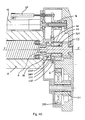
- FIGS. 1 and 2 show a wheel W on which a tire T is mounted.
- the wheel is rotatably mounted on a wheel carrier K, the axis XX being its axis of rotation.
- a casing 1 closed by a cover 2 and by the stator part S of a motor electric traction M.
- the housing has an upper extension 10 and a lower extension 11 to the ends of which can be attached a system of suspension of wheel W with respect to a chassis or to the vehicle body.
- the casing 1 defines an enclosed space with the cover 2 and the electric motor M. This enclosed space may contain the amount of oil required to lubricate the mechanical parts installed there.
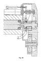
- a toothed wheel 3 see figure 1 and figures 3
- rotatable around the axis XX in direct engagement with the wheel W.
- the toothed wheel 3 is meshed with a first pinion 31.
- the first pinion 31 is coaxial and integral with an auxiliary pinion 310 of diameter larger than the diameter of the first gear 31.
- the first gear 31 and the auxiliary pinion 310 form a single rotary mechanical piece (see Figure 4A).
- the auxiliary pinion 310 is meshed on an intermediate pinion 6.
- the pinion 6 allows the same direction of rotation of the electric motor to be maintained whatever the report engaged.
- the toothed wheel 3 is meshed with a second pinion 53.
- the pinion of second 53 is coaxial and integral with a sprocket 530 (see in particular Figure 3A and Figure 4A).
- the second pinion 53 and the interchangeable pinion 530 form a part mechanical monobloc rotary.
- This mechanical part has a clearance peripheral 532 without teeth, adjoining the interchangeable pinion 530 (see in particular Figure 4A).
- This mechanical part also has a bearing smooth intermediate 531.
- a clutch pinion idler 42 is mounted on the bearing smooth intermediate 531, coaxial with the second pinion 53, so that it can rotate freely relative to the second pinion 53.
- the gear change mechanism includes a dog clutch 46 allowing select a report.
- the dog clutch 46 has teeth interior identical to the toothing (exterior) of the sprocket 530 and the idler Doggy 42.
- Doggy 46 can be dogged either on the idler pinion 42 for have a reduction ( Figure 3A and 4A), either on the sprocket 530 for drive in direct drive ( Figure 3C and 4C), or the dog clutch 46 can be brought into a non-clutch position in which its internal toothing faces the clearance 532 free of any teeth ( Figures 3B and 4B).
- the dog clutch 46 has an outer peripheral groove 460 and recesses 461 (see figure 5).
- a shaft end A (figures 4) of the motor rotor electric M the axis YY being the axis of rotation of the shaft A.
- a bell 38 is mounted secured to the shaft A of the rotor of the electric motor M.
- the dog clutch 46 is centered by the bell 38.
- a fork 16 is engaged radially from the outside in the groove peripheral 460 fitted on the dog clutch 46.
- the bell 38 has fingers 380 engaged in the recesses 461 of the dog clutch 46.
- the dog clutch 46 can slide axially by relative to the bell, while being integral in rotation thereof.
- the first gear 31 and the second gear 53 are continuously driven by the toothed wheel 3. With identical teeth, they both rotate at the same speed angular.
- the second pinion 53 when it is engaged with the shaft A of the motor rotor electric M via the second auxiliary pinion 530, the dog clutch 46 and the bell 38, is engaged direct with the motor M.
- the traction torque passes through the pinion of first 31, via the bell 38, the dog clutch 46, the idler gear 42, the intermediate gear 6 and the auxiliary pinion 310, there is between the shaft A of the rotor of the electric motor M and the pinion first 31 a reduction ratio corresponding to the ratio R between the number auxiliary pinion teeth 310 and the number of idler pinion teeth 42.
- the dog causes the toothed wheel 3 via an intermediate pinion 6 making it possible to reverse the speed of rotation.
- the pinion 6 makes it possible to maintain the same direction of rotation of the electric motor which whether the gear engaged: direct drive or other mechanical transmission path.
- a gear change implies an almost instantaneous and significant change in the speed of electric traction motor.
- the change can for example be made in synchronism at least on the wheels on the same axle of the vehicle.
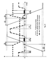
- a shifting involves canceling the engine torque (zone 1), shifting the gearbox speed in neutral position (zone 2), then involves adjusting the motor rotation speed at the level corresponding to the future report selected (zone 3), in order to be able to engage mechanically said ratio, before piloting the engine again to the desired torque.
- the torque at the wheel is roughly equivalent. If we are going towards a greater total reduction (going from second to first), this requires voluntarily limiting the torque of the electric motor immediately after the maneuver gear change. The decrease in torque is noticeable in the R report. If we go towards a smaller total reduction (go from first to second), this requires voluntarily increasing the electric torque just after the operation of gear switch. The increase in torque is noticeable in the R report. However, the torque available to the motor is necessarily limited to a value Cmax.
- the actual gear change is achieved by a single electronic assembly ensuring the control of the two electric traction motors of an axle and the control of the gearshift mechanism on both wheels of the axle (or, in the case of two driving axles, by two electronic assemblies ensuring the control, each, of axle components).
- This electronic assembly receives a change order from report from the CPU and sends it, after execution, a report.
- the time to complete the gear change is about 300 ms.
- the vehicle speed to be taken into account during the gear change is therefore the last value calculated before the start of the gear change operation.
- 3 * 0.3 0.9 m / s i.e. 3 km / h approximately. It is obvious that this approximation remains valid for average accelerations or decelerations and provided that the time of change of gear is respected.
- the time can be shifted gear changes on both axles: first gear shift on one axle then gear change on the other axle.
- the speed of the wheels affected by a gear change will be calculated by the calculation unit from the traction motor speed information and current report on the other axle, the wheel or wheels of said other axle then playing the role of so-called "sensor wheel”.
- the speeds of the wheels concerned are transmitted by the bus CAN ® to the control electronics of the first axle, including the so-called wheels “Maneuvered wheels”. Then we start again by changing the axle for the wheel roles sensor and wheel operated.
- the calculation detects one of the two sensor wheels in an abnormal situation (blocking or skating), the vehicle speed information will be generated from the other wheel of the same axle. If the two wheels of the axle with the sensor wheels are in a situation abnormal (blocking or slipping) just before initiating the gear change order, the shift order will not be sent until a situation is returned normal. If the abnormal situation (blocking or slipping) on both wheels of the axle with the sensor wheels occurs while the gear change procedure is in progress on the other axle, The calculation unit sends as information "speed vehicle ”, the last calculated information deemed reliable. Another possible solution is next: stay neutral on the wheels while changing gears until the speed given by the sensor wheel (s) has become reliable again.
- the changes in reports on the two wheels first change of report on the left wheel by example, then gear change on the right wheel.
- the vehicle speed will be calculated locally by the traction electronics from the traction motor speed and ratio information course on the right wheel (sensor wheel), and vice versa.
- the calculation unit detects the sensor wheel in a situation abnormal (blocking or slipping), the gear change order will not be sent until returning to a normal situation. If the abnormal situation (blocking or slipping) on the sensor wheel arrives while the gear change procedure is in progress on the other wheel, we use as vehicle speed information, the last information calculated reliable. Again, another possible solution is: stay neutral on the wheel changing gear until the vehicle speed given by the wheel sensor has become reliable again.
- the invention proposes a method for controlling the gear change for a vehicle having at least two driving wheels each equipped with a traction chain similar to what was described above, in which the time is shifted gear changes on two-wheel drive: in an initial phase, gear change on a so-called “maneuvered” wheel, the vehicle speed being calculated by the traction electronics from the traction motor speed information and report in progress on the other wheel called “sensor wheel”, then in a following phase, gear change on said other wheel.
- the vehicle speed being calculated by the traction electronics from the traction motor speed information and report in progress on the other wheel called “sensor wheel”, then in a following phase, gear change on said other wheel.
- at least one sensor wheel is located on one of the axles, the driven wheels being on the other axle during the initial phase, and there are reversal of the locations of the “sensor” and “maneuvered” wheels in the phase successive.
Landscapes
- Engineering & Computer Science (AREA)
- Mechanical Engineering (AREA)
- Transportation (AREA)
- Chemical & Material Sciences (AREA)
- Combustion & Propulsion (AREA)
- Power Engineering (AREA)
- General Engineering & Computer Science (AREA)
- Electric Propulsion And Braking For Vehicles (AREA)
- Structure Of Transmissions (AREA)
- Arrangement Of Transmissions (AREA)
- Motor Power Transmission Devices (AREA)
- Arrangement Or Mounting Of Propulsion Units For Vehicles (AREA)
- Control Of Stepping Motors (AREA)
- Control Of Transmission Device (AREA)
Abstract
Description
- un porte roue supportant un moyeu rotatif destiné à recevoir une roue motrice et matérialisant un axe de rotation pour ladite roue motrice,
- une roue dentée rotative, ayant le même axe de rotation que l'axe de rotation de ladite roue motrice, la roue dentée étant en prise directe avec le moyeu,
- un arrangement comportant au moins deux pignons engrenés en permanence avec ladite roue dentée, comportant un arbre d'entrée destiné à être couplé avec l'arbre d'un moteur électrique, et comportant un mécanisme de changement de rapport avec position neutre entre rapports, ledit mécanisme comprenant une prise directe entre l'arbre d'entrée et l'un des pignons, ledit mécanisme comportant, entre l'arbre d'entrée et l'autre des pignons, au moins une autre voie mécanique de transmission à démultiplication différente de la prise directe.
- la figure 1 montre une roue de véhicule dans laquelle est intégrée la chaíne électrique de traction selon l'invention, vue en coupe selon C/C indiqué à la figure 2 ;
- la figure 2 est une vue selon A à la figure 1 ;
- les figures 3A, 3B et 3C sont des perspectives partielles montrant la chaíne électromécanique de transmission ;
- les figures 4A, 4B et 4C sont des coupes selon 4/4 à la figure 2, montrant les organes essentiels du mécanisme de changement de rapport à deux rapports ;
- la figure 5 est une vue partielle de la chaíne électromécanique de transmission ;
- la figure 6 est un chronogramme montrant l'évolution au cours du temps pendant les changements de rapports de la position de la fourchette de commande, de la vitesse du moteur de traction et du couple du moteur de traction.
- une position dans laquelle le crabot 46 entraíne la roue dentée via un pignon intermédiaire 6 permettant d'inverser la vitesse de rotation ; le crabot 46 est alors craboté avec le pignon fou 42, donc en prise avec le pignon de première 31, via les pignons intermédiaire 6 et auxiliaire 310 (voir notamment figures 3A et 4A) ; c'est ladite autre voie mécanique de transmission ;
- une position dans laquelle il est craboté avec le pignon auxiliaire 530, donc en prise avec le pignon de deuxième 53 (voir notamment figures 3C et 4C),
- une position intermédiaire neutre, visible aux figure 3B et 4B.
- sur le 1er rapport (grande réduction) de profiter d'un couple important au niveau de la roue, donc avoir des performances dynamiques élevées.
- Sur le 2ème rapport (réduction moindre) de permettre d'atteindre la vitesse maximale prévue du véhicule.
- D'envisager dans certains cas des véhicules à 2 roues motrices au lieu de 4, en augmentant le couple au démarrage (diminution du matériel installé donc de la masse et du prix).
- capteurs : position pédale d'accélérateur, position ou pression pédale de frein, position du volant, position papillon des gaz et régime moteur thermique (si le véhicule est équipé d'un moteur thermique),
- informations provenant des électroniques de traction : vitesses des moteurs, rapports actuellement engagés ; ces informations sont envoyées régulièrement (toutes les 10ms par exemple) par l'intermédiaire d'un bus CAN ® ou un bus de type similaire. L'unité de calcul peut alors, à partir de ces informations, calculer la vitesse de chacune des roues.
- le capteur de position intégré au moteur électrique synchrone autopiloté,
- les capteurs de position équipant le dispositif de changement de rapport (boite de vitesse en prise directe ou en position démultipliée).
- Contrôle rapport 1 engagé.
- Calcul vitesse de la roue à partir de « vitesse moteur traction » et « rapport 1 engagé ».
- Couple moteur ramené à zéro.
- Passage au neutre.
- Réajustement vitesse moteur, sur la base de la vitesse de la roue calculée ci-dessus.
- Engagement rapport 2
- Contrôle rapport 2 engagé
- Rétablissement du couple moteur.
Claims (16)
- Chaíne de traction pour véhicule automobile, caractérisée en ce qu'elle comprend :un porte roue (K) supportant un moyeu rotatif destiné à recevoir une roue (W) motrice et matérialisant un axe de rotation pour ladite roue motrice,une roue dentée (3) rotative, ayant le même axe de rotation que l'axe de rotation de ladite roue motrice, la roue dentée étant en prise directe avec le moyeu,un arrangement comportant au moins deux pignons (31 et 53) engrenés en permanence avec ladite roue dentée, comportant un arbre d'entrée destiné à être couplé avec l'arbre d'un moteur électrique, et comportant un mécanisme de changement de rapport avec position neutre entre rapports, ledit mécanisme comprenant une prise directe entre l'arbre d'entrée et l'un des pignons, ledit mécanisme comportant, entre l'arbre d'entrée et l'autre des pignons, au moins une autre voie mécanique de transmission à démultiplication différente de la prise directe.
- Chaíne de traction selon la revendication 1, caractérisée en ce que le mécanisme de changement de rapport comporte un crabot (46) permettant de sélectionner l'un ou l'autre des rapports.
- Chaíne de traction selon la revendication 1 caractérisée en ce que, dans ladite autre voie mécanique de transmission, le crabot (46) entraíne la roue dentée via un pignon intermédiaire (6) permettant d'inverser la vitesse de rotation.
- Chaíne de traction selon la revendication 1 caractérisée en ce que, dans ladite autre voie mécanique de transmission, le crabot (46) entraíne la roue directement, sans pignon intermédiaire.
- Chaíne de traction selon la revendication 1, caractérisée en ce qu'elle est dépourvue d'embrayage à friction.
- Chaíne de traction selon la revendication 1, caractérisée en ce qu'elle est à deux rapports seulement.
- Chaíne de traction selon la revendication 1 caractérisée en ce qu'elle comporte un moteur électrique (M), dans laquelle le moteur électrique est du type synchrone auto piloté, le moteur comportant au moins un capteur de position du rotor intégré et utilisé pour assurer le pilotage du moteur.
- Chaíne de traction selon la revendication 7, caractérisée en ce que les seuls capteurs utilisés pour déterminer la vitesse de rotation de la roue sont ledit capteur de position intégré au moteur et un ensemble capteur associé au mécanisme de changement de rapport.
- Procédé de pilotage du changement de rapport pour un véhicule ayant au moins deux roues motrices chacune équipée d'une chaíne de traction selon la revendication 7 ou 8, dans lequel on décale dans le temps les changements de rapports sur les deux roues motrices : dans une phase initiale, changement de rapport sur une roue dite « manoeuvrée », la vitesse véhicule étant calculée par l'électronique de traction à partir des informations vitesse moteur de traction et rapport en cours sur l'autre roue dite « roue capteur », puis dans une phase suivante, changement de rapport sur ladite autre roue.
- Procédé de pilotage du changement de rapport selon la revendication 9, pour un véhicule ayant au moins quatre roues motrices dans deux essieux, dans lequel au moins une roue capteur est située sur l'un des essieux, les roues manoeuvrées étant sur l'autre essieu pendant la phase initiale, et inversion des localisations des roues « capteur » et « manoeuvrée » dans la phase successive.
- Procédé selon l'une des revendications 9 ou 10 dans lequel on interdit la procédure de changement de rapport en cas de freinage supérieur à un seuil prédéterminé.
- Procédé selon la revendication 9 dans lequel on détecte, pendant la procédure de changement de rapport, le blocage ou le patinage sur la roue capteur et on utilise comme information « vitesse véhicule » la dernière information calculée jugée fiable.
- Procédé selon la revendication 9 dans lequel on détecte, pendant la procédure de changement de rapport, le blocage ou le patinage sur la roue capteur et on reste au neutre sur la roue manoeuvrée jusqu'à ce que la vitesse de la roue capteur soit redevenue fiable.
- Procédé selon la revendication 10 utilisant deux roues capteurs dans un essieu, dans lequel on détecte, pendant la procédure de changement de rapport, le blocage ou le patinage d'une roue capteur et on élabore l'information vitesse à partir de l'autre roue capteur.
- Procédé selon la revendication 10 utilisant deux roues capteurs dans un essieu, dans lequel on détecte pendant la procédure de changement de rapport le blocage ou le patinage des deux roues capteurs et on utilise comme information « vitesse véhicule » la dernière information calculée jugée fiable.
- Procédé selon la revendication 10 utilisant deux roues capteurs dans un essieu, dans lequel on détecte pendant la procédure de changement de rapport le blocage ou le patinage des deux roues capteurs et on reste au neutre sur les roues manoeuvrées jusqu'à ce que la vitesse d'au moins une roue de l'essieu capteur soit redevenue fiable.
Applications Claiming Priority (2)
| Application Number | Priority Date | Filing Date | Title |
|---|---|---|---|
| FR0208930 | 2002-07-15 | ||
| FR0208930A FR2842147A1 (fr) | 2002-07-15 | 2002-07-15 | Chaine de traction comportant un mecanisme de changement de rapport integre dans une roue |
Publications (2)
| Publication Number | Publication Date |
|---|---|
| EP1382476A1 true EP1382476A1 (fr) | 2004-01-21 |
| EP1382476B1 EP1382476B1 (fr) | 2006-08-30 |
Family
ID=29763879
Family Applications (1)
| Application Number | Title | Priority Date | Filing Date |
|---|---|---|---|
| EP03015773A Expired - Lifetime EP1382476B1 (fr) | 2002-07-15 | 2003-07-10 | Chaine de traction comportant un mecanisme de changement de rapport integre dans une roue et procédé de changement de rapport associé |
Country Status (7)
| Country | Link |
|---|---|
| US (1) | US7165640B2 (fr) |
| EP (1) | EP1382476B1 (fr) |
| JP (1) | JP4593090B2 (fr) |
| CN (1) | CN1313298C (fr) |
| AT (1) | ATE337935T1 (fr) |
| DE (1) | DE60307940T2 (fr) |
| FR (1) | FR2842147A1 (fr) |
Cited By (2)
| Publication number | Priority date | Publication date | Assignee | Title |
|---|---|---|---|---|
| FR2984241A1 (fr) * | 2011-12-20 | 2013-06-21 | Michelin Soc Tech | Moyeu motorise pour la motorisation electrique d'un essieu d'un vehicule automobile a traction hybride |
| WO2014013084A1 (fr) | 2012-07-20 | 2014-01-23 | Compagnie Generale Des Etablissements Michelin | Moyeu motorise comprenant un changement de rapport et des moyens de couplage et de decouplage |
Families Citing this family (26)
| Publication number | Priority date | Publication date | Assignee | Title |
|---|---|---|---|---|
| US20060124368A1 (en) * | 2003-03-28 | 2006-06-15 | Plishner Paul J | Vehicle with a distributed motor |
| ATE372477T1 (de) * | 2003-07-09 | 2007-09-15 | Michelin Rech Tech | Verfahren zum gangwechsel eines antriebsstranges der für jedes antriebsrad einen schaltmechanismus besitzt |
| DE102005017723A1 (de) * | 2005-04-15 | 2006-10-26 | Zf Friedrichshafen Ag | Antriebseinheit für ein Flurförderfahrzeug |
| JP4820189B2 (ja) * | 2006-03-09 | 2011-11-24 | 本田技研工業株式会社 | 車両用ホイール駆動装置の配置構造 |
| US7363995B2 (en) * | 2006-05-01 | 2008-04-29 | American Axle & Manufacturing, Inc. | Overrunning clutch and method of controlling engagement of same |
| US7364524B2 (en) * | 2006-05-01 | 2008-04-29 | American Axel & Manufacturing, Inc. | Driveline coupling for electric module |
| US20070251742A1 (en) * | 2006-05-01 | 2007-11-01 | Adams Herbert L Iii | Vehicle with hybrid power train providing part-time all-wheel drive |
| US20100181126A1 (en) * | 2009-01-16 | 2010-07-22 | Penrod Fred F | Electric car battery charging system |
| DE102009054726A1 (de) * | 2009-12-16 | 2011-06-22 | ZF Friedrichshafen AG, 88046 | Antriebseinheit eines Flurförderzeugs |
| DE102009054727A1 (de) * | 2009-12-16 | 2011-06-22 | ZF Friedrichshafen AG, 88046 | Antriebseinheit eines Flurförderzeugs |
| FR2953773B1 (fr) * | 2009-12-16 | 2012-04-27 | Michelin Soc Tech | Moyeu motorise comprenant des moyens de couplage et de decouplage. |
| DE102010022320A1 (de) | 2010-06-01 | 2011-12-01 | Schaeffler Technologies Gmbh & Co. Kg | Elektrischer Radantrieb |
| DE102012204795A1 (de) | 2012-03-26 | 2013-09-26 | Schaeffler Technologies AG & Co. KG | Radnabenmotor mit Potenzialausgleich |
| US9862263B2 (en) * | 2013-03-01 | 2018-01-09 | Delbert Tesar | Multi-speed hub drive wheels |
| US10414271B2 (en) * | 2013-03-01 | 2019-09-17 | Delbert Tesar | Multi-speed hub drive wheels |
| JP2016003730A (ja) * | 2014-06-18 | 2016-01-12 | 株式会社リコー | 駆動伝達機構、画像形成装置および回転体検査装置 |
| CN104085298B (zh) * | 2014-06-23 | 2017-01-04 | 北京理工大学 | 正差速式机电复合传动装置 |
| CN108340775B (zh) * | 2016-01-27 | 2020-11-20 | 陈安 | 一种电动汽车 |
| CN113815393A (zh) | 2016-05-06 | 2021-12-21 | 艾里逊变速箱公司 | 具有电动机的车桥总成 |
| US10711865B2 (en) * | 2016-12-27 | 2020-07-14 | Nabtesco Corporation | Speed reducing device for carriage and driving device for carriage |
| USD883864S1 (en) | 2018-05-10 | 2020-05-12 | Allison Transmission, Inc. | Axle assembly |
| CN110654222A (zh) * | 2018-06-29 | 2020-01-07 | 比亚迪股份有限公司 | 轮边驱动系统以及车辆 |
| WO2020008257A1 (fr) | 2018-07-03 | 2020-01-09 | Ka Group Ag | Essieu de véhicule électrique |
| JP7053405B2 (ja) * | 2018-08-17 | 2022-04-12 | Ntn株式会社 | 車両駆動装置 |
| USD927578S1 (en) | 2018-09-27 | 2021-08-10 | Allison Transmission, Inc. | Axle assembly |
| DE102018221606A1 (de) * | 2018-12-13 | 2020-06-18 | Zf Friedrichshafen Ag | Elektromotorisch angetriebene Starrachse für Fahrzeuge, insbesondere Nutzfahrzeuge, und Verfahren zu deren Betrieb, Computerprogrammprodukt, Steuerungs- und/oder Regelungsvorrichtung und Kraftfahrzeug |
Citations (5)
| Publication number | Priority date | Publication date | Assignee | Title |
|---|---|---|---|---|
| DE1655194A1 (de) * | 1967-12-07 | 1971-07-15 | Bosch Gmbh Robert | Selbsttaetige Schalteinrichtung fuer mindestens zwei Antriebsmotor-Getriebeeinheiten aufweisende Kraftfahrzeuge |
| US4083421A (en) * | 1976-12-06 | 1978-04-11 | Horn Ronald L Van | Two speed motorcycle hub transmission |
| EP0700805A2 (fr) * | 1994-09-07 | 1996-03-13 | Seiko Epson Corporation | Système d'entraînement, unité de propulsion électrique et unité de transmisson de puissance pour des véhicules électriques |
| EP0807772A2 (fr) * | 1996-05-14 | 1997-11-19 | Voith Turbo GmbH & Co. KG | Méthode pour l'entraînement d'un véhicule avec plusieurs machines motrices |
| DE19723776A1 (de) * | 1996-06-14 | 1997-12-18 | Deere & Co | Elektrischer Einzelradantrieb für ein Arbeitsfahrzeug |
Family Cites Families (18)
| Publication number | Priority date | Publication date | Assignee | Title |
|---|---|---|---|---|
| US1481706A (en) * | 1920-08-09 | 1924-01-22 | Adam M Goodwin | Reversing mechanism |
| US4094556A (en) * | 1968-04-24 | 1978-06-13 | Nippondenso Kabushiki Kaisha | Anti-skid system for a vehicle |
| GB1463500A (en) * | 1973-06-09 | 1977-02-02 | Cragg H | Wheelchairs |
| JPS6114690Y2 (fr) * | 1980-09-17 | 1986-05-08 | ||
| JPS57150649U (fr) * | 1981-03-18 | 1982-09-21 | ||
| CN85101503B (zh) * | 1985-04-01 | 1987-12-23 | 王启振 | 车轮的直接驱动装置 |
| CN85203823U (zh) * | 1985-09-10 | 1986-07-09 | 重庆电机厂 | 用于轻便电动车特别是电动自行车的轮式驱动电机 |
| US4899279A (en) * | 1986-04-07 | 1990-02-06 | Eaton Corporation | Method for controlling AMT system including wheel lock-up detection and tolerance |
| JPS63258351A (ja) * | 1987-04-16 | 1988-10-25 | Fuji Photo Film Co Ltd | 回転速度切換機構 |
| JPS6460440A (en) * | 1987-08-31 | 1989-03-07 | Fuji Heavy Ind Ltd | Control device for constant speed traveling of vehicle with continuously variable transmission |
| US5038633A (en) * | 1989-09-28 | 1991-08-13 | Kabushiki Kaisha Kobe Seiko Sho | Transmission for mini shovel car |
| FR2679842A1 (fr) * | 1991-07-29 | 1993-02-05 | Shm Management Services Ag | Module de roulement moteur, notamment pour vehicule automobile. |
| KR100231550B1 (ko) * | 1996-09-17 | 1999-11-15 | 류정열 | 전기자동차용 변속장치 |
| JP2001030772A (ja) * | 1999-07-21 | 2001-02-06 | Unitec Kk | 車輪モータ |
| JP2001277866A (ja) * | 2000-03-29 | 2001-10-10 | Hitachi Car Eng Co Ltd | 電動運搬車用駆動装置 |
| JP2002031197A (ja) * | 2000-05-12 | 2002-01-31 | Kayseven Co Ltd | 変速装置 |
| US6511397B2 (en) * | 2001-01-30 | 2003-01-28 | Ford Global Technologies, Inc. | Method and apparatus for controlling a transfer case which reacts to rate of change of throttle position |
| JP2002337554A (ja) * | 2001-05-16 | 2002-11-27 | Mazda Motor Corp | 車両の駆動装置配設構造 |
-
2002
- 2002-07-15 FR FR0208930A patent/FR2842147A1/fr active Pending
-
2003
- 2003-07-10 AT AT03015773T patent/ATE337935T1/de not_active IP Right Cessation
- 2003-07-10 DE DE60307940T patent/DE60307940T2/de not_active Expired - Lifetime
- 2003-07-10 EP EP03015773A patent/EP1382476B1/fr not_active Expired - Lifetime
- 2003-07-14 US US10/617,680 patent/US7165640B2/en not_active Expired - Fee Related
- 2003-07-15 JP JP2003274579A patent/JP4593090B2/ja not_active Expired - Fee Related
- 2003-07-15 CN CNB031495346A patent/CN1313298C/zh not_active Expired - Fee Related
Patent Citations (5)
| Publication number | Priority date | Publication date | Assignee | Title |
|---|---|---|---|---|
| DE1655194A1 (de) * | 1967-12-07 | 1971-07-15 | Bosch Gmbh Robert | Selbsttaetige Schalteinrichtung fuer mindestens zwei Antriebsmotor-Getriebeeinheiten aufweisende Kraftfahrzeuge |
| US4083421A (en) * | 1976-12-06 | 1978-04-11 | Horn Ronald L Van | Two speed motorcycle hub transmission |
| EP0700805A2 (fr) * | 1994-09-07 | 1996-03-13 | Seiko Epson Corporation | Système d'entraînement, unité de propulsion électrique et unité de transmisson de puissance pour des véhicules électriques |
| EP0807772A2 (fr) * | 1996-05-14 | 1997-11-19 | Voith Turbo GmbH & Co. KG | Méthode pour l'entraînement d'un véhicule avec plusieurs machines motrices |
| DE19723776A1 (de) * | 1996-06-14 | 1997-12-18 | Deere & Co | Elektrischer Einzelradantrieb für ein Arbeitsfahrzeug |
Cited By (3)
| Publication number | Priority date | Publication date | Assignee | Title |
|---|---|---|---|---|
| FR2984241A1 (fr) * | 2011-12-20 | 2013-06-21 | Michelin Soc Tech | Moyeu motorise pour la motorisation electrique d'un essieu d'un vehicule automobile a traction hybride |
| WO2013092303A1 (fr) * | 2011-12-20 | 2013-06-27 | Compagnie Generale Des Etablissements Michelin | Moyeu motorisé pour la motorisation électrique d'un essieu d'un véhicule automobile à traction hybride |
| WO2014013084A1 (fr) | 2012-07-20 | 2014-01-23 | Compagnie Generale Des Etablissements Michelin | Moyeu motorise comprenant un changement de rapport et des moyens de couplage et de decouplage |
Also Published As
| Publication number | Publication date |
|---|---|
| DE60307940T2 (de) | 2007-04-05 |
| FR2842147A1 (fr) | 2004-01-16 |
| US7165640B2 (en) | 2007-01-23 |
| CN1313298C (zh) | 2007-05-02 |
| ATE337935T1 (de) | 2006-09-15 |
| JP4593090B2 (ja) | 2010-12-08 |
| US20040007406A1 (en) | 2004-01-15 |
| DE60307940D1 (de) | 2006-10-12 |
| JP2004036894A (ja) | 2004-02-05 |
| EP1382476B1 (fr) | 2006-08-30 |
| CN1477000A (zh) | 2004-02-25 |
Similar Documents
| Publication | Publication Date | Title |
|---|---|---|
| EP1382476B1 (fr) | Chaine de traction comportant un mecanisme de changement de rapport integre dans une roue et procédé de changement de rapport associé | |
| EP1496292B1 (fr) | Procédé de changement de rapport pour chaîne de traction comportant un mécanisme de changement de rapport pour chaque roue motrice | |
| EP2405156B1 (fr) | Dispositif de transmission de vitesse pour un véhicule automobile de type hybride | |
| FR2799417A1 (fr) | Dispositif de controle de vehicule, notamment pour la repartition des forces de traction avant-arriere | |
| FR2822758A1 (fr) | Chaine motrice | |
| FR2816554A1 (fr) | Systeme de transmission de vehicule et dispositif de changement de vitesse pour cette transmission | |
| FR2817311A1 (fr) | Vehicule motorise | |
| WO2014013084A1 (fr) | Moyeu motorise comprenant un changement de rapport et des moyens de couplage et de decouplage | |
| FR2844858A1 (fr) | Differentiel asymetrique a caractere actif pour vehicule automobile | |
| FR2792260A1 (fr) | Dispositif de manoeuvre | |
| EP4192725B1 (fr) | Dispositif de transmission pour véhicule à propulsion humaine | |
| FR3056160B1 (fr) | Transmission pour vehicule automobile a propulsion electrique | |
| FR3116802A1 (fr) | Ensemble de transmission pour engin de mobilité | |
| EP1050643B1 (fr) | Serrure comprenant un actionneur électrique en particulier pour ouvrant de véhicule automobile | |
| FR2796339A1 (fr) | Boite de vitesses mecanique en ligne, pour vehicule a propulsion hybride | |
| EP2400188A1 (fr) | Système de pilotage d'une boîte de vitesse automatique à embrayages à passage de rapports sans rupture à la roue | |
| EP2273154A1 (fr) | Boite de vitesses à dérivation de couple et procédé de passages associé | |
| FR2858036A1 (fr) | Procede de changement de rapport pour chaine de traction comportant un mecanisme de changement de rapport pour chaque roue motrice. | |
| FR2857426A1 (fr) | Procede de changement de rapport pour chaine de traction comportant un mecanisme de changement de rapport pour chaque roue motrice | |
| EP4499442B1 (fr) | Véhicule à motorisation électrique et procédé de pilotage d'un tel véhicule | |
| FR2897134A1 (fr) | Groupe motopropulseur hybride optimise pour l'engagement de la premiere vitesse et de la marche arriere | |
| WO2025056840A1 (fr) | Procédé de pilotage d'un blocage d'un differentiel de vitesse d'un train de roues arrière | |
| HK40117831B (en) | Vehicle with electric drive and control method for such vehicle | |
| HK40117831A (en) | Vehicle with electric drive and control method for such vehicle | |
| EP3478547B1 (fr) | Dispositif de controle d'un frein de stationnement de vehicule automobile |
Legal Events
| Date | Code | Title | Description |
|---|---|---|---|
| PUAI | Public reference made under article 153(3) epc to a published international application that has entered the european phase |
Free format text: ORIGINAL CODE: 0009012 |
|
| AK | Designated contracting states |
Kind code of ref document: A1 Designated state(s): AT BE BG CH CY CZ DE DK EE ES FI FR GB GR HU IE IT LI LU MC NL PT RO SE SI SK TR |
|
| AX | Request for extension of the european patent |
Extension state: AL LT LV MK |
|
| 17P | Request for examination filed |
Effective date: 20040721 |
|
| AKX | Designation fees paid |
Designated state(s): AT BE BG CH CY CZ DE DK EE ES FI FR GB GR HU IE IT LI LU MC NL PT RO SE SI SK TR |
|
| GRAP | Despatch of communication of intention to grant a patent |
Free format text: ORIGINAL CODE: EPIDOSNIGR1 |
|
| GRAS | Grant fee paid |
Free format text: ORIGINAL CODE: EPIDOSNIGR3 |
|
| GRAA | (expected) grant |
Free format text: ORIGINAL CODE: 0009210 |
|
| AK | Designated contracting states |
Kind code of ref document: B1 Designated state(s): AT BE BG CH CY CZ DE DK EE ES FI FR GB GR HU IE IT LI LU MC NL PT RO SE SI SK TR |
|
| PG25 | Lapsed in a contracting state [announced via postgrant information from national office to epo] |
Ref country code: IT Free format text: LAPSE BECAUSE OF FAILURE TO SUBMIT A TRANSLATION OF THE DESCRIPTION OR TO PAY THE FEE WITHIN THE PRESCRIBED TIME-LIMIT;WARNING: LAPSES OF ITALIAN PATENTS WITH EFFECTIVE DATE BEFORE 2007 MAY HAVE OCCURRED AT ANY TIME BEFORE 2007. THE CORRECT EFFECTIVE DATE MAY BE DIFFERENT FROM THE ONE RECORDED. Effective date: 20060830 Ref country code: IE Free format text: LAPSE BECAUSE OF FAILURE TO SUBMIT A TRANSLATION OF THE DESCRIPTION OR TO PAY THE FEE WITHIN THE PRESCRIBED TIME-LIMIT Effective date: 20060830 Ref country code: NL Free format text: LAPSE BECAUSE OF FAILURE TO SUBMIT A TRANSLATION OF THE DESCRIPTION OR TO PAY THE FEE WITHIN THE PRESCRIBED TIME-LIMIT Effective date: 20060830 Ref country code: RO Free format text: LAPSE BECAUSE OF FAILURE TO SUBMIT A TRANSLATION OF THE DESCRIPTION OR TO PAY THE FEE WITHIN THE PRESCRIBED TIME-LIMIT Effective date: 20060830 Ref country code: SI Free format text: LAPSE BECAUSE OF FAILURE TO SUBMIT A TRANSLATION OF THE DESCRIPTION OR TO PAY THE FEE WITHIN THE PRESCRIBED TIME-LIMIT Effective date: 20060830 Ref country code: FI Free format text: LAPSE BECAUSE OF FAILURE TO SUBMIT A TRANSLATION OF THE DESCRIPTION OR TO PAY THE FEE WITHIN THE PRESCRIBED TIME-LIMIT Effective date: 20060830 Ref country code: SK Free format text: LAPSE BECAUSE OF FAILURE TO SUBMIT A TRANSLATION OF THE DESCRIPTION OR TO PAY THE FEE WITHIN THE PRESCRIBED TIME-LIMIT Effective date: 20060830 Ref country code: CZ Free format text: LAPSE BECAUSE OF FAILURE TO SUBMIT A TRANSLATION OF THE DESCRIPTION OR TO PAY THE FEE WITHIN THE PRESCRIBED TIME-LIMIT Effective date: 20060830 Ref country code: AT Free format text: LAPSE BECAUSE OF FAILURE TO SUBMIT A TRANSLATION OF THE DESCRIPTION OR TO PAY THE FEE WITHIN THE PRESCRIBED TIME-LIMIT Effective date: 20060830 |
|
| REG | Reference to a national code |
Ref country code: GB Ref legal event code: FG4D Free format text: NOT ENGLISH |
|
| REG | Reference to a national code |
Ref country code: CH Ref legal event code: EP |
|
| REG | Reference to a national code |
Ref country code: IE Ref legal event code: FG4D Free format text: LANGUAGE OF EP DOCUMENT: FRENCH |
|
| REF | Corresponds to: |
Ref document number: 60307940 Country of ref document: DE Date of ref document: 20061012 Kind code of ref document: P |
|
| GBT | Gb: translation of ep patent filed (gb section 77(6)(a)/1977) |
Effective date: 20061101 |
|
| PG25 | Lapsed in a contracting state [announced via postgrant information from national office to epo] |
Ref country code: BG Free format text: LAPSE BECAUSE OF FAILURE TO SUBMIT A TRANSLATION OF THE DESCRIPTION OR TO PAY THE FEE WITHIN THE PRESCRIBED TIME-LIMIT Effective date: 20061130 Ref country code: DK Free format text: LAPSE BECAUSE OF FAILURE TO SUBMIT A TRANSLATION OF THE DESCRIPTION OR TO PAY THE FEE WITHIN THE PRESCRIBED TIME-LIMIT Effective date: 20061130 Ref country code: SE Free format text: LAPSE BECAUSE OF FAILURE TO SUBMIT A TRANSLATION OF THE DESCRIPTION OR TO PAY THE FEE WITHIN THE PRESCRIBED TIME-LIMIT Effective date: 20061130 |
|
| PG25 | Lapsed in a contracting state [announced via postgrant information from national office to epo] |
Ref country code: ES Free format text: LAPSE BECAUSE OF FAILURE TO SUBMIT A TRANSLATION OF THE DESCRIPTION OR TO PAY THE FEE WITHIN THE PRESCRIBED TIME-LIMIT Effective date: 20061211 |
|
| PG25 | Lapsed in a contracting state [announced via postgrant information from national office to epo] |
Ref country code: PT Free format text: LAPSE BECAUSE OF FAILURE TO SUBMIT A TRANSLATION OF THE DESCRIPTION OR TO PAY THE FEE WITHIN THE PRESCRIBED TIME-LIMIT Effective date: 20070212 |
|
| NLV1 | Nl: lapsed or annulled due to failure to fulfill the requirements of art. 29p and 29m of the patents act | ||
| REG | Reference to a national code |
Ref country code: IE Ref legal event code: FD4D |
|
| PLBE | No opposition filed within time limit |
Free format text: ORIGINAL CODE: 0009261 |
|
| STAA | Information on the status of an ep patent application or granted ep patent |
Free format text: STATUS: NO OPPOSITION FILED WITHIN TIME LIMIT |
|
| 26N | No opposition filed |
Effective date: 20070531 |
|
| REG | Reference to a national code |
Ref country code: FR Ref legal event code: TP |
|
| BERE | Be: lapsed |
Owner name: CONCEPTION ET DEVELOPPEMENT MICHELIN S.A. Effective date: 20070731 |
|
| REG | Reference to a national code |
Ref country code: CH Ref legal event code: PL |
|
| PG25 | Lapsed in a contracting state [announced via postgrant information from national office to epo] |
Ref country code: GR Free format text: LAPSE BECAUSE OF FAILURE TO SUBMIT A TRANSLATION OF THE DESCRIPTION OR TO PAY THE FEE WITHIN THE PRESCRIBED TIME-LIMIT Effective date: 20061201 Ref country code: CH Free format text: LAPSE BECAUSE OF NON-PAYMENT OF DUE FEES Effective date: 20070731 Ref country code: MC Free format text: LAPSE BECAUSE OF NON-PAYMENT OF DUE FEES Effective date: 20070731 Ref country code: LI Free format text: LAPSE BECAUSE OF NON-PAYMENT OF DUE FEES Effective date: 20070731 |
|
| PG25 | Lapsed in a contracting state [announced via postgrant information from national office to epo] |
Ref country code: EE Free format text: LAPSE BECAUSE OF FAILURE TO SUBMIT A TRANSLATION OF THE DESCRIPTION OR TO PAY THE FEE WITHIN THE PRESCRIBED TIME-LIMIT Effective date: 20060830 |
|
| PG25 | Lapsed in a contracting state [announced via postgrant information from national office to epo] |
Ref country code: BE Free format text: LAPSE BECAUSE OF NON-PAYMENT OF DUE FEES Effective date: 20070731 |
|
| PG25 | Lapsed in a contracting state [announced via postgrant information from national office to epo] |
Ref country code: LU Free format text: LAPSE BECAUSE OF NON-PAYMENT OF DUE FEES Effective date: 20070710 Ref country code: CY Free format text: LAPSE BECAUSE OF FAILURE TO SUBMIT A TRANSLATION OF THE DESCRIPTION OR TO PAY THE FEE WITHIN THE PRESCRIBED TIME-LIMIT Effective date: 20060830 |
|
| PG25 | Lapsed in a contracting state [announced via postgrant information from national office to epo] |
Ref country code: HU Free format text: LAPSE BECAUSE OF FAILURE TO SUBMIT A TRANSLATION OF THE DESCRIPTION OR TO PAY THE FEE WITHIN THE PRESCRIBED TIME-LIMIT Effective date: 20070301 Ref country code: TR Free format text: LAPSE BECAUSE OF FAILURE TO SUBMIT A TRANSLATION OF THE DESCRIPTION OR TO PAY THE FEE WITHIN THE PRESCRIBED TIME-LIMIT Effective date: 20060830 |
|
| REG | Reference to a national code |
Ref country code: FR Ref legal event code: PLFP Year of fee payment: 13 |
|
| PGFP | Annual fee paid to national office [announced via postgrant information from national office to epo] |
Ref country code: FR Payment date: 20150626 Year of fee payment: 13 |
|
| PGFP | Annual fee paid to national office [announced via postgrant information from national office to epo] |
Ref country code: DE Payment date: 20150721 Year of fee payment: 13 Ref country code: GB Payment date: 20150721 Year of fee payment: 13 |
|
| PGFP | Annual fee paid to national office [announced via postgrant information from national office to epo] |
Ref country code: IT Payment date: 20150727 Year of fee payment: 13 |
|
| REG | Reference to a national code |
Ref country code: DE Ref legal event code: R119 Ref document number: 60307940 Country of ref document: DE |
|
| GBPC | Gb: european patent ceased through non-payment of renewal fee |
Effective date: 20160710 |
|
| PG25 | Lapsed in a contracting state [announced via postgrant information from national office to epo] |
Ref country code: FR Free format text: LAPSE BECAUSE OF NON-PAYMENT OF DUE FEES Effective date: 20160801 Ref country code: DE Free format text: LAPSE BECAUSE OF NON-PAYMENT OF DUE FEES Effective date: 20170201 |
|
| REG | Reference to a national code |
Ref country code: FR Ref legal event code: ST Effective date: 20170331 |
|
| PG25 | Lapsed in a contracting state [announced via postgrant information from national office to epo] |
Ref country code: GB Free format text: LAPSE BECAUSE OF NON-PAYMENT OF DUE FEES Effective date: 20160710 |
|
| PG25 | Lapsed in a contracting state [announced via postgrant information from national office to epo] |
Ref country code: IT Free format text: LAPSE BECAUSE OF NON-PAYMENT OF DUE FEES Effective date: 20160710 |