EP1382852A2 - Innenläuferzahnradölpumpe - Google Patents
Innenläuferzahnradölpumpe Download PDFInfo
- Publication number
- EP1382852A2 EP1382852A2 EP03015651A EP03015651A EP1382852A2 EP 1382852 A2 EP1382852 A2 EP 1382852A2 EP 03015651 A EP03015651 A EP 03015651A EP 03015651 A EP03015651 A EP 03015651A EP 1382852 A2 EP1382852 A2 EP 1382852A2
- Authority
- EP
- European Patent Office
- Prior art keywords
- tooth
- curve
- rotor
- rolling
- oil pump
- Prior art date
- Legal status (The legal status is an assumption and is not a legal conclusion. Google has not performed a legal analysis and makes no representation as to the accuracy of the status listed.)
- Granted
Links
- 239000012208 gear oil Substances 0.000 title 1
- 238000005096 rolling process Methods 0.000 claims description 288
- 238000000926 separation method Methods 0.000 claims description 32
- 239000012530 fluid Substances 0.000 claims description 24
- 238000007599 discharging Methods 0.000 claims description 7
- 230000000295 complement effect Effects 0.000 description 46
- 230000003247 decreasing effect Effects 0.000 description 9
- 230000007423 decrease Effects 0.000 description 8
- 238000010586 diagram Methods 0.000 description 4
- 230000004048 modification Effects 0.000 description 4
- 238000012986 modification Methods 0.000 description 4
- 230000005540 biological transmission Effects 0.000 description 2
- 230000010349 pulsation Effects 0.000 description 2
- 238000005086 pumping Methods 0.000 description 2
- 230000000712 assembly Effects 0.000 description 1
- 238000000429 assembly Methods 0.000 description 1
- 230000015556 catabolic process Effects 0.000 description 1
- 238000006731 degradation reaction Methods 0.000 description 1
- 238000005461 lubrication Methods 0.000 description 1
Images






Classifications
-
- F—MECHANICAL ENGINEERING; LIGHTING; HEATING; WEAPONS; BLASTING
- F04—POSITIVE - DISPLACEMENT MACHINES FOR LIQUIDS; PUMPS FOR LIQUIDS OR ELASTIC FLUIDS
- F04C—ROTARY-PISTON, OR OSCILLATING-PISTON, POSITIVE-DISPLACEMENT MACHINES FOR LIQUIDS; ROTARY-PISTON, OR OSCILLATING-PISTON, POSITIVE-DISPLACEMENT PUMPS
- F04C2/00—Rotary-piston machines or pumps
- F04C2/08—Rotary-piston machines or pumps of intermeshing-engagement type, i.e. with engagement of co-operating members similar to that of toothed gearing
- F04C2/10—Rotary-piston machines or pumps of intermeshing-engagement type, i.e. with engagement of co-operating members similar to that of toothed gearing of internal-axis type with the outer member having more teeth or tooth-equivalents, e.g. rollers, than the inner member
-
- F—MECHANICAL ENGINEERING; LIGHTING; HEATING; WEAPONS; BLASTING
- F04—POSITIVE - DISPLACEMENT MACHINES FOR LIQUIDS; PUMPS FOR LIQUIDS OR ELASTIC FLUIDS
- F04C—ROTARY-PISTON, OR OSCILLATING-PISTON, POSITIVE-DISPLACEMENT MACHINES FOR LIQUIDS; ROTARY-PISTON, OR OSCILLATING-PISTON, POSITIVE-DISPLACEMENT PUMPS
- F04C2/00—Rotary-piston machines or pumps
- F04C2/08—Rotary-piston machines or pumps of intermeshing-engagement type, i.e. with engagement of co-operating members similar to that of toothed gearing
- F04C2/082—Details specially related to intermeshing engagement type machines or pumps
- F04C2/084—Toothed wheels
-
- F—MECHANICAL ENGINEERING; LIGHTING; HEATING; WEAPONS; BLASTING
- F04—POSITIVE - DISPLACEMENT MACHINES FOR LIQUIDS; PUMPS FOR LIQUIDS OR ELASTIC FLUIDS
- F04C—ROTARY-PISTON, OR OSCILLATING-PISTON, POSITIVE-DISPLACEMENT MACHINES FOR LIQUIDS; ROTARY-PISTON, OR OSCILLATING-PISTON, POSITIVE-DISPLACEMENT PUMPS
- F04C2/00—Rotary-piston machines or pumps
- F04C2/08—Rotary-piston machines or pumps of intermeshing-engagement type, i.e. with engagement of co-operating members similar to that of toothed gearing
- F04C2/10—Rotary-piston machines or pumps of intermeshing-engagement type, i.e. with engagement of co-operating members similar to that of toothed gearing of internal-axis type with the outer member having more teeth or tooth-equivalents, e.g. rollers, than the inner member
- F04C2/102—Rotary-piston machines or pumps of intermeshing-engagement type, i.e. with engagement of co-operating members similar to that of toothed gearing of internal-axis type with the outer member having more teeth or tooth-equivalents, e.g. rollers, than the inner member the two members rotating simultaneously around their respective axes
Definitions
- This invention relates to an oil pump rotor assembly used in an oil pump which draws and discharges fluid by volume change of cells formed between an inner rotor and an outer rotor.
- an oil pump which are generally compact and simply constructed, are widely used as pumps for lubrication oil in automobiles and as oil pumps for automatic transmissions, etc.
- Such an oil pump comprises an inner rotor having "n" external teeth (hereinafter “n” indicates a natural number), an outer rotor having "n+1" internal teeth which are engageable with the external teeth, and a casing in which a suction port for drawing fluid and a discharge port for discharging fluid are formed, and fluid is drawn and is discharged by rotation of the inner rotor which produces changes in the volumes of cells formed between the inner rotor and the outer rotor.
- an object of the present invention is to reduce noise emitted from an oil pump while preventing pumping performance and mechanical efficiency thereof from being degraded by properly forming the profiles of teeth of an inner rotor and an outer rotor of the oil pump.
- the width of a tooth tip is increased by separating a cycloid curve, which defines the tooth tip, at a midpoint thereof by a predetermined distance, thereby gap (or clearance) between the tooth surfaces, which is defined in the direction of tooth width when the rotors engage each other, is decreased.
- the tooth tip profile of an inner rotor is formed such that an epicycloid curve, which is generated by rolling a circumscribed-rolling circle Ai along a base circle Di without slip, is equally divided into two at a midpoint thereof to obtain two outer tooth curve segments, and the two outer tooth curve segments are separated by a predetermined distance and are smoothly connected to each other using a curve or a straight line.
- each of the tooth profiles of an outer rotor is formed such that the tooth space profile thereof is formed using an epicycloid curve which is generated by rolling a circumscribed-rolling circle Ao along a base circle Do without slip, and the tooth tip profile thereof is formed using a hypocycloid curve which is generated by rolling an inscribed-rolling circle Bo along the base circle Do without slip.
- the tooth space profile of the inner rotor is formed based on a hypocycloid curve which is formed by rolling an inscribed-rolling circle Bi along the base circle Di without slip.
- the separation of the two outer tooth curve segments may be performed in such a manner that the two outer tooth curve segments are moved along the circumference of the base circle Di.
- the separation of the two outer tooth curve segments may be performed in such a manner that the two outer tooth curve segments are moved in the direction of a tangent of the epicycloid curve drawn at the midpoint thereof.
- the separation of the two outer tooth curve segments may be performed in such a manner that the two outer tooth curve segments are first moved along the circumference of the base circle Di, and then moved in the direction of a tangent of the epicycloid curve drawn at the midpoint thereof.
- the separation of the two outer tooth curve segments may be performed in such a manner that the two outer tooth curve segments are first moved in the direction of a tangent of the epicycloid curve drawn at the midpoint thereof, and then moved along the circumference of the base circle Di.
- the inner rotor and the outer rotor are preferably formed such that the following inequalities are satisfied: t/4 ⁇ 3t/4, where, "t” is the magnitude of a tip clearance (i.e., the total distance of gaps formed between the tooth surfaces of the inner and outer rotors along the line passing through the centers of the inner and outer rotors in a rotational phase in which the tooth tip apex of the outer tooth of the inner rotor and the tooth tip apex of the inner tooth of the outer rotor oppose each other), and " ⁇ " is the predetermined distance between the two outer tooth curve segments.
- t is the magnitude of a tip clearance (i.e., the total distance of gaps formed between the tooth surfaces of the inner and outer rotors along the line passing through the centers of the inner and outer rotors in a rotational phase in which the tooth tip apex of the outer tooth of the inner rotor and the tooth tip apex of the inner tooth of the outer rotor oppose each other),
- the tooth tip profile of an outer rotor is formed such that a hypocycloid curve. which is generated by rolling an inscribed-rolling circle Bo along a base circle Do without slip, is equally divided into two at a midpoint thereof to obtain two inner tooth curve segments, and the two inner tooth curve segments are separated by a predetermined distance and are smoothly connected to each other using a curve or a straight line.
- the tooth space profile of the outer rotor is formed based on a hypocycloid curve which is formed by rolling a circumscribed-rolling circle Ao along the base circle Do without slip.
- Each of the tooth profiles of an inner rotor is formed such that the tooth tip profile thereof is formed using an epicycloid curve which is generated by rolling a circumscribed-rolling circle Ai along a base circle Di without slip, and the tooth space profile thereof is formed using a hypocycloid curve which is generated by rolling an inscribed-rolling circle Bi along the base circle Di without slip.
- the separation of the two inner tooth curve segments may be performed in such a manner that the two inner tooth curve segments are moved along the circumference of the base circle Do.
- the separation of the two inner tooth curve segments may be performed in such a manner that the two inner tooth curve segments are moved in the direction of a tangent of the hypocycloid curve drawn at the midpoint thereof.
- the separation of the two inner tooth curve segments may be performed in such a manner that the two inner tooth curve segments are first moved along the circumference of the base circle Do, and then moved in the direction of a tangent of the hypocycloid curve drawn at the midpoint thereof.
- the separation of the two inner tooth curve segments may be performed in such a manner that the two inner tooth curve segments are first moved in the direction of a tangent of the hypocycloid curve drawn at the midpoint thereof, and then moved along the circumference of the base circle Do.
- the inner rotor and the outer rotor are preferably formed such that the following inequalities are satisfied: t/4 ⁇ 3t/4, where, "t” is the magnitude of a tip clearance, and " ⁇ ” is the predetermined distance between the two inner tooth curve segments.
- the tooth tip profile of an inner rotor is formed such that an epicycloid curve, which is generated by rolling a circumscribed-rolling circle Ai along a base circle Di without slip, is equally divided into two at a midpoint thereof to obtain two outer tooth curve segments. and the two outer tooth curve segments are separated by a predetermined distance and are smoothly connected to each other using a curve or a straight line.
- a hypocycloid curve which is generated by rolling an inscribed-rolling circle Bo along a base circle Do without slip, is equally divided into two at a midpoint thereof to obtain two inner tooth curve segments, and the two inner tooth curve segments are separated by a predetermined distance and are smoothly connected to each other using a curve or a straight line.
- the tooth space profile of the inner rotor is formed based on a hypocycloid curve which is formed by rolling an inscribed-rolling circle Bi along the base circle Di without slip.
- the tooth space profile of the outer rotor is formed based on an epicycloid curve which is formed by rolling a circumscribed-rolling circle Ao along the base circle Do without slip.
- the separation of the two outer tooth curve segments may be performed in such a manner that the two outer tooth curve segments are moved along the circumference of the base circle Di, and the separation of the two inner tooth curve segments may be performed in such a manner that the two inner tooth curve segments are moved along the circumference of the base circle Do.
- the separation of the two outer tooth curve segments may be performed in such a manner that the two outer tooth curve segments are moved in the direction of a tangent of the epicycloid curve drawn at the midpoint thereof, the separation of the two inner tooth curve segments may be performed in such a manner that the two inner tooth curve segments are moved in the direction of a tangent of the hypocycloid curve drawn at the midpoint thereof.
- the separation of the two outer tooth curve segments may be performed in such a manner that the two outer tooth curve segments are first moved along the circumference of the base circle Di, and then moved in the direction of a tangent of the epicycloid curve drawn at the midpoint thereof, and the separation of the two inner tooth curve segments may be performed in such a manner that the two inner tooth curve segments are first moved along the circumference of the base circle Do, and then moved in the direction of a tangent of the hypocycloid curve drawn at the midpoint thereof.
- the separation of the two outer tooth curve segments may be performed in such a manner that the two outer tooth curve segments are first moved in the direction of a tangent of the epicycloid curve drawn at the midpoint thereof, and then moved along the circumference of the base circle Di, and the separation of the two inner tooth curve segments may be performed in such a manner that the two inner tooth curve segments are first moved in the direction of a tangent of the hypocycloid curve drawn at the midpoint thereof, and then moved along the circumference of the base circle Do.
- the inner rotor and the outer rotor are preferably formed such that the following inequalities are satisfied: t/4 ⁇ 3t/4; and t/4 ⁇ 3t/4, where "t"' is a tip clearance, " ⁇ " is the predetermined distance between the two outer tooth curve segments, and “ ⁇ ” is the predetermined distance between the two inner tooth curve segments.
- ⁇ Bi is the diameter of the inscribed-rolling circle Bi
- ⁇ Do is the diameter of the base circle Do of the outer rotor
- ⁇ Ao is the diameter of the circumscribed-rolling circle Ao
- ⁇ Bo is the diameter of the inscribed-rolling circle Bo
- "e" is an eccentric distance between the inner rotor and the outer rotor.
- At least one of the tooth profile of the inner rotor and the tooth profile of the outer rotor is formed such that the circumferential thickness of the tooth tip is slightly greater than that of a conventional one by equally dividing a cycloid curve for defining the tooth profile into two at a midpoint thereof to obtain two tooth curve segments, and by moving the two tooth curve segments along the circumference of the base circle or by moving in the direction of a tangent of the cycloid curve drawn at the midpoint thereof; therefore, an oil pump rotor assembly, in which not only the tip clearance but also clearance between the tooth surfaces are appropriately ensured, can be obtained.
- the circumferential thickness of the tooth tip is made to be greater than that of a conventional one without changing the position of the tooth tip apex; therefore, an oil pump rotor assembly, which emits less noise, and which exhibits better mechanical performance when compared with a conventional one, can be obtained.
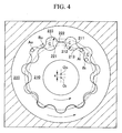
- FIGS. 1 to 3C A first embodiment of an oil pump rotor assembly according to the present invention will be explained below with reference to FIGS. 1 to 3C.
- each of the cells C is delimited at a front portion and at a rear portion as viewed in the direction of rotation of the inner rotor 110 and outer rotor 120 by contact regions between the external teeth 111 of the inner rotor 110 and the internal teeth 121 of the outer rotor 120, and is also delimited at either side portions by the casing 30, so that an independent fluid conveying chamber is formed.
- Each of the cells C moves while the inner rotor 110 and outer rotor 120 rotate, and the volume of each of the cells C cyclically increases and decreases so as to complete one cycle in a rotation.
- a suction port which communicates with one of the cells C whose volume increases gradually
- a discharge port which communicates with one of the cells C whose volume decreases gradually, and fluid drawn into one of the cells C through the suction port is transported as the rotors 110 and 120 rotate, and is discharged through the discharge port.
- a clearance that is formed between the apex of the tooth tip 112 of the inner rotor 110 and the apex of the tooth tip 122 of the outer rotor 120, which face each other on a line passing through the centers Oi and Oo of the rotors, is designated by a tip clearance.
- the size "t 1 " of this tip clearance is defined as the size of a tip clearance that is formed in a state in which the rotors 110 and 120 are disposed such that clearance between the tooth tip 112 of the inner rotor 110 and the tooth space 123 of the outer rotor 120, which engage each other on the line passing through the centers Oi and Oo at a diametrically opposing position. is zero.
- the center Oi of the inner rotor 110 and the center Oo of the outer rotor 120 are disposed to have an eccentric distance therebetween so that the same clearance t 1 /2 is formed between the tooth surfaces at two positions, located on the line passing through the centers Oi and Oo, at which the tooth surfaces face each other.
- the eccentric distance between the centers Oi and Oo is designated by "e”.
- the inner rotor 110 is mounted on a rotational axis so as to be rotatable about the center Oi, and the tooth profile of each of the external teeth 111 of the inner rotor 110 is formed using an epicycloid curve 116, which is generated by rolling a circumscribed-rolling circle Ai (whose diameter is ⁇ Ai) along the base circle Di (whose diameter is ⁇ Di) of the inner rotor 110 without slip, and using a hypocycloid curve 117, which is generated by rolling an inscribed-rolling circle Bi (whose diameter is ⁇ Bi) along the base circle Di without slip.
- the outer rotor 120 is mounted so as to be rotatable about the center Oo. and the center thereof is positioned so as to have an offset (the eccentric distance is "e") from the center Oi.
- the tooth profile of each of the internal teeth 121 of the outer rotor 120 is formed using an epicycloid curve 127, which is generated by rolling a circumscribed-rolling circle Ao (whose diameter is ⁇ Ao) along the base circle Do (whose diameter is ⁇ Do) of the outer rotor 120 without slip, and using a hypocycloid curve 126, which is generated by rolling an inscribed-rolling circle Bo (whose diameter is ⁇ Bo) along the base circle Do without slip.
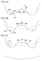
- each of the external teeth 111 of the inner rotor 110 is formed by alternately arranging tooth tips 112 and tooth spaces 113 in the circumferential direction.
- the epicycloid curve 116 (FIG. 2A) generated by the circumscribed-rolling circle Ai is equally divided at a midpoint A 1 thereof into two segments that are designated by outer tooth curve segments 112a and 112b, respectively.
- the midpoint A of the epicycloid curve 116 is a point that symmetrically divides the epicycloid curve 116 into two which is generated by a specific point on the circumscribed-rolling circle Ai by rolling the circumscribed-rolling circle Ai by one turn on the base circle Di of the inner rotor 110 without slip.
- the midpoint A 1 is a point that is reached by the specific point when the circumscribed-rolling circle Ai rolls a half turn.
- the outer tooth curve segments 112a and 112b are moved about the center Oi and along the circumference of the base circle Di so that a distance " ⁇ 1 " is ensured between the outer tooth curve segments 112a and 112b.
- ⁇ i 1 an angle defined by two lines, which are drawn by connecting the center Oi of the base circle Di and the ends of the outer tooth curve segments 112a and 112b, is designated by ⁇ i 1 .
- the separated ends of the outer tooth curve segments 112a and 112b are connected to each other by a complementary line 114 consisting of a straight line, and the obtained continuous curve is used as the profile of the tooth tip 112.
- the tooth tip 112 is formed using a continuous curve that includes the outer tooth curve segments 112a and 112b, which are separated from each other, and the complementary line 114 connecting the outer tooth curve segment 112a with the outer tooth curve segment 112b.
- the circumferential thickness of the tooth tip 112 is greater than a tooth tip which is formed just using the simple epicycloid curve 116 by an amount corresponding to the angle ⁇ i 1 defined by two lines, which are drawn by connecting the center Oi of the base circle Di and the ends of the complementary line 114.
- the complementary line 114 which connects the outer tooth curve segment 112a with the outer tooth curve segment 112b, is a straight line; however, the complementary line 114 may be a curve.
- the circumferential thickness of the tooth tip 112 is made to be greater than that of a conventional tooth tip as explained above, and on the other hand, in this embodiment, the width of the tooth space 113 is decreased, and tooth profiles are smoothly connected to each other over the entirety of the circumference.
- the hypocycloid curve 117 (FIG. 2A) generated by the inscribed-rolling circle Bi is equally divided at a midpoint B 1 thereof into two segments that are designated by curve segments 113a and 113b, respectively.
- the midpoint B 1 of the hypocycloid curve 117 is a point that symmetrically divides the hypocycloid curve 117 into two which is generated by a specific point on the inscribed-rolling circle Bi by rolling the inscribed-rolling circle Bi by one turn on the base circle Di of the inner rotor 110 without slip.
- the midpoint B 1 is a point that is reached by the specific point when the inscribed-rolling circle Bi rolls a half turn.
- the curve segments 113a and 113b are moved along the circumference of the base circle Di so that the ends of the curve segments 113a and 113b are respectively connected to the ends of the continuous curve that forms the tooth tip 112.
- the curve segments 113a and 113b overlap each other while intersecting each other at the midpoint B 1 , and an angle, which is defined by an overlap portion 115 and the center Oi of the base circle Di, equals ⁇ i 1 .
- the curve segments 113a and 113b are smoothly connected to each other so as to form a continuous curve that defines the tooth profile of the tooth space 113.
- the circumferential width of the tooth space 113 is less than that of a tooth space which is formed just using the simple hypocycloid curve 117 by an amount corresponding to the angle ⁇ i 1 .
- the circumferential thickness of the tooth tip 112 is made to be greater and the circumferential width of the tooth space 113 is reduced when compared with the case in which tooth profiles are formed just using the epicycloid curve 116 and the hypocycloid curve 117 that are generated by the circumscribed-rolling circle Ai and the inscribed-rolling circle Bi, respectively.
- the distance " ⁇ 1 " between the outer tooth curve segment 112a and the outer tooth curve segment 112b is set so as to satisfy the following inequality: t 1 /4 ⁇ 1 , and more preferably, the distance " ⁇ 1 " is set so as to satisfy the following inequality: 2t 1 /5 ⁇ 1 .As a result, the clearance between the tooth surfaces with respect to the outer rotor 120 are appropriately ensured, and quietness can be sufficiently improved.
- the distance " ⁇ 1 " between the outer tooth curve segment 112a and the outer tooth curve segment 112b is set so as to satisfy the following inequality: ⁇ 1 ⁇ 3t 1 /4, and more preferably, the distance " ⁇ 1 " is set so as to satisfy the following inequality: ⁇ 1 ⁇ 3t 1 /5.
- the internal teeth 121 of the outer rotor 120 are formed by alternately arranging tooth tips 122 and tooth spaces 123 in the circumferential direction.
- the hypocycloid curve 126 (FIG. 3A) generated by the inscribed-rolling circle Bo is equally divided at a midpoint C 1 thereof into two segments that are designated by inner tooth curve segments 122a and 122b, respectively.
- the midpoint C 1 of the hypocycloid curve 126 is a point that symmetrically divides the hypocycloid curve 126 into two which is generated by a specific point on the inscribed-rolling circle Bo by rolling the inscribed-rolling circle Bo by one turn on the base circle Do of the outer rotor 120 without slip.
- the midpoint C 1 is a point that is reached by the specific point when the inscribed-rolling circle Bo rolls a half turn.
- the inner tooth curve segments 122a and 122b are moved along the circumference of the base circle Do so that a distance " ⁇ 1 " is ensured between the inner tooth curve segments 122a and 122b.
- ⁇ 1 an angle defined by two lines, which are drawn by connecting the center Oo of the base circle Do and the ends of the inner tooth curve segments 122a and 122b, is designated by ⁇ o 1 .
- the separated ends of the inner tooth curve segments 122a and 122b are connected to each other by a complementary line 124 consisting of a straight line, and the obtained continuous curve is used as the profile of the tooth tip 122.
- the tooth tip 122 is formed using a continuous curve that includes the inner tooth curve segments 122a and 122b, which are separated from each other, and the complementary line 124 connecting the inner tooth curve segment 122a with the inner tooth curve segment 122b.
- the circumferential thickness of the tooth tip 122 is greater than a tooth tip which is formed just using the simple hypocycloid curve 126 by an amount corresponding to the angle ⁇ o 1 defined by two lines, which are drawn by connecting the center Oo of the base circle Do and the ends of the complementary line 124.
- the complementary line 124 which connects the inner tooth curve segment 122a with the inner tooth curve segment 122b, is a straight line; however, the complementary line 124 may be a curve.
- the circumferential thickness of the tooth tip 122 is made to be greater than that of a conventional tooth tip as explained above, and on the other hand, in this embodiment, the width of the tooth space 123 is decreased, and tooth profiles are smoothly connected to each other over the entirety of the circumference.
- the epicycloid curve 127 (FIG. 3A) generated by the circumscribed-rolling circle Ao is equally divided at a midpoint D 1 thereof into two segments that are designated by curve segments 123a and 123b, respectively.
- the midpoint D 1 of the epicycloid curve 127 is a point that symmetrically divides the epicycloid curve 127 into two which is generated by a specific point on the circumscribed-rolling circle Ao by rolling the circumscribed-rolling circle Ao by one turn on the base circle Do of the outer rotor 120 without slip.
- the midpoint D 1 is a point that is reached by the specific point when the circumscribed-rolling circle Ao rolls a half turn.
- the curve segments 123a and 123b are moved along the circumference of the base circle Do so that the ends of the curve segments 123a and 123b are respectively connected to the ends of the continuous curve that forms the tooth tip 122.
- the curve segments 123a and 123b overlap each other while intersecting each other at the midpoint D 1 , and an angle, which is defined by an overlap portion 125 and the center Oo of the base circle Do, equals ⁇ o 1 .
- the curve segments 123a and 123b are smoothly connected to each other so as to form a continuous curve that defines the tooth profile of the tooth space 123.
- the circumferential width of the tooth space 123 is less than that of a tooth space which is formed just using the simple epicycloid curve 127 by an amount corresponding to the angle ⁇ o 1 .
- the circumferential thickness of the tooth tip 122 is made to be greater and the circumferential width of the tooth space 123 is reduced when compared with the case in which tooth profiles are formed just using epicycloid curve 127 and the hypocycloid curve 126 that are generated by the circumscribed-rolling circle Ao and the inscribed-rolling circle Bo, respectively.
- the distance " ⁇ 1 " between the outer tooth curve segment 122a and the outer tooth curve segment 122b is set so as to satisfy the following inequality: t 1 /4 ⁇ 1 , and more preferably, the distance " ⁇ 1 " is set so as to satisfy the following inequality: 2t 1 /5 ⁇ ⁇ 1 .
- the distance " ⁇ 1 " between the outer tooth curve segment 122a and the outer tooth curve segment 122b is set so as to satisfy the following inequality: ⁇ 1 ⁇ 3t 1 /4, and more preferably, the distance " ⁇ 1 " is set so as to satisfy the following inequality: ⁇ 1 ⁇ 3t 1 /5.
- the circumferential thicknesses of both tooth tip 112 of the inner rotor 110 and tooth tip 122 of the outer rotor 120 are increased when compared with conventional cases; however, the present invention is not limited to this, and other configurations may be employed in which one of the tooth tip 112 of the inner rotor 110 and tooth tip 122 of the outer rotor 120 is made thicker, and the tooth profile of the other tooth tip is formed using a cycloid curve without modification.
- the oil pump rotor assembly of the present invention may be formed using the base curves that satisfy the above relationships.
- the oil pump rotor assembly of the present invention may be formed using the base curves that satisfy the above relationships.
- each of the cells C is delimited at a front portion and at a rear portion as viewed in the direction of rotation of the inner rotor 210 and outer rotor 220 by contact regions between the external teeth 211 of the inner rotor 210 and the internal teeth 221 of the outer rotor 220, and is also delimited at either side portions by the casing 30, so that an independent fluid conveying chamber is formed.
- Each of the cells C moves while the inner rotor 210 and outer rotor 220 rotate, and the volume of each of the cells C cyclically increases and decreases so as to complete one cycle in a rotation.
- a suction port which communicates with one of the cells C whose volume increases gradually
- a discharge port which communicates with one of the cells C whose volume decreases gradually, and fluid drawn into one of the cells C through the suction port is transported as the rotors 210 and 220 rotate, and is discharged through the discharge port.
- a clearance that is formed between the apex of the tooth tip 212 of the inner rotor 210 and the apex of the tooth tip 222 of the outer rotor 220, which face each other on a line passing through the centers Oi and Oo of the rotors, is designated by a tip clearance.
- the size "t 2 " of this tip clearance is defined as the size of a tip clearance that is formed in a state in which the rotors 210 and 220 are disposed such that clearance between the tooth tip 212 of the inner rotor 210 and the tooth space 223 of the outer rotor 220, which engage each other on the line passing through the centers Oi and Oo at a diametrically opposing position, is zero.
- the center Oi of the inner rotor 210 and the center Oo of the outer rotor 220 are disposed to have an eccentric distance therebetween so that the same clearance t 2 /2 is formed between the tooth surfaces at two positions, located on the line passing through the centers Oi and Oo, at which the tooth surfaces face each other.
- the eccentric distance between the centers Oi and Oo is designated by "e”.
- the inner rotor 210 is mounted on a rotational axis so as to be rotatable about the center Oi, and the tooth profile of each of the external teeth 211 of the inner rotor 210 is formed using an epicycloid curve 216, which is generated by rolling a circumscribed-rolling circle Ai (whose diameter is ⁇ Ai) along the base circle Di (whose diameter is ⁇ Di) of the inner rotor 210 without slip, and using a hypocycloid curve 217, which is generated by rolling an inscribed-rolling circle Bi (whose diameter is ⁇ Bi) along the base circle Di without slip.
- the outer rotor 220 is mounted so as to be rotatable about the center Oo, and the center thereof is positioned so as to have an offset (the eccentric distance is "e") from the center Oi.
- the tooth profile of each of the internal teeth 221 of the outer rotor 220 is formed using an epicycloid curve 227, which is generated by rolling a circumscribed-rolling circle Ao (whose diameter is ⁇ Ao) along the base circle Do (whose diameter is ⁇ Do) of the outer rotor 220 without slip, and using a hypocycloid curve 226, which is generated by rolling an inscribed-rolling circle Bo (whose diameter is ⁇ Bo) along the base circle Do without slip.
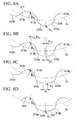
- the detailed profile of each of the external teeth 211 of the inner rotor 210 will be explained with reference to FIGS. 5A to 5C.
- the external teeth 211 of the inner rotor 210 are formed by alternately arranging tooth tips 212 and tooth spaces 213 in the circumferential direction.
- the epicycloid curve 216 (FIG. 5A) generated by the circumscribed-rolling circle Ai is equally divided at a midpoint A 2 thereof into two segments that are designated by outer tooth curve segments 212a and 212b, respectively.
- the outer tooth curve segments 212a and 212b are moved in the direction of a tangent of the epicycloid curve 216 drawn at the midpoint A 2 thereof so that a distance " ⁇ 2 " is ensured between the outer tooth curve segments 212a and 212b.
- the separated ends of the outer tooth curve segments 212a and 212b are connected to each other by a complementary line 214 consisting of a straight line, and the obtained continuous curve is used as the profile of the tooth tip 212.
- the tooth tip 212 is formed using a continuous curve that includes the outer tooth curve segments 212a and 212b, which are separated from each other, and the complementary line 214 connecting the outer tooth curve segment 212a with the outer tooth curve segment 212b.
- the circumferential thickness of the tooth tip 212 of the inner rotor 210 is greater than a tooth tip which is formed just using the simple epicycloid curve 216 by an amount corresponding to the interposing complementary line 214.
- the complementary line 214 which connects the outer tooth curve segment 212a with the outer tooth curve segment 212b, is a straight line; however, the complementary line 214 may be a curve.
- the circumferential thickness of the tooth tip 212 is made to be greater than that of a conventional tooth tip as explained above, and on the other hand, in this embodiment, the width of the tooth space 213 is decreased, and tooth profiles are smoothly connected to each other over the entirety of the circumference.
- the hypocycloid curve 217(FIG. 5A) generated by the inscribed-rolling circle Bi is equally divided at a midpoint B 2 thereof into two segments that are designated by curve segments 213a and 213b, respectively.
- the curve segments 213a and 213b are moved in the direction of a tangent of the hypocycloid curve 217 drawn at the midpoint B 2 thereof so that the ends of the curve segments 213a and 213b are respectively connected to the ends of the continuous curve that forms the tooth tip 212.
- the curve segments 213a and 213b overlap each other while intersecting each other at the midpoint B 2 .
- the curve segments 213a and 213b are smoothly connected to each other so as to form a continuous curve that defines the tooth profile of the tooth space 213.
- the circumferential width of the tooth space 213 is less than that of a tooth space which is formed just using the simple hypocycloid curve 217 by an amount corresponding to the complementary line 214 interposing in the tooth tip 212.
- the circumferential thickness of the tooth tip 212 is made to be greater and the circumferential width of the tooth space 213 is reduced when compared with the case in which tooth profiles are formed just using the epicycloid curve 216 and the hypocycloid curve 217 that are generated by the circumscribed-rolling circle Ai and the inscribed-rolling circle Bi. respectively.
- the distance " ⁇ 2 " between the outer tooth curve segment 212a and the outer tooth curve segment 212b is set so as to satisfy the following inequality: t 2 /4 ⁇ 2 , and more preferably, the distance " ⁇ 2 " is set so as to satisfy the following inequality: 2t 2 /5 ⁇ 2 .
- the distance " ⁇ 2 " between the outer tooth curve segment 212a and the outer tooth curve segment 212b is set so as to satisfy the following inequality: ⁇ 2 ⁇ 3t 2 /4, and more preferably, the distance " ⁇ 2 " is set so as to satisfy the following inequality: ⁇ 2 ⁇ 3t 2 /5.
- the internal teeth 221 of the outer rotor 220 are formed by alternately arranging tooth tips 222 and tooth spaces 223 in the circumferential direction.
- the hypocycloid curve 226 (FIG. 6A) generated by the inscribed-rolling circle Bo is equally divided at a midpoint C 2 thereof into two segments that are designated by inner tooth curve segments 222a and 222b. respectively.
- the inner tooth curve segments 222a and 222b are moved in the direction of a tangent of the hypocycloid curve 226 drawn at the midpoint C 2 thereof so that a distance " ⁇ 2 " is ensured between the inner tooth curve segments 222a and 222b.
- the separated ends of the inner tooth curve segments 222a and 222b are connected to each other by a complementary line 224 consisting of a straight line, and the obtained continuous curve is used as the profile of the tooth tip 222.
- the tooth tip 222 is formed using a continuous curve that includes the inner tooth curve segments 222a and 222b, which are separated from each other, and the complementary line 224 connecting the inner tooth curve segment 222a with the inner tooth curve segment 222b.
- the circumferential thickness of the tooth tip 222 is greater than a tooth tip which is formed just using the simple hypocycloid curve 226 by an amount corresponding to the interposing complementary line 224.
- the complementary line 224 which connects the inner tooth curve segment 222a with the inner tooth curve segment 222b, is a straight line; however, the complementary line 224 may be a curve.
- the circumferential thickness of the tooth tip 222 is made to be greater than that of a conventional tooth tip as explained above, and on the other hand, in this embodiment.
- the width of the tooth space 223 is decreased, and tooth profiles are smoothly connected to each other over the entirety of the circumference.
- the epicycloid curve 227 (FIG. 6A) generated by the circumscribed-rolling circle Ao is equally divided at a midpoint D 2 thereof into two segments that are designated by curve segments 223a and 223b, respectively.
- the curve segments 223a and 223b are moved in the direction of a tangent of the epicycloid curve 227 drawn at the midpoint D 2 thereof so that the ends of the curve segments 223a and 223b are respectively connected to the ends of the continuous curve that forms the tooth tip 222, and the curve segments 223a and 223b overlap each other while intersecting each other at the midpoint D 2 .
- the curve segments 223a and 223b are smoothly connected to each other so as to form a continuous curve that defines the tooth profile of the tooth space 223.
- the circumferential width of the tooth space 223 is less than that of a tooth space which is formed just using the simple epicycloid curve 227 by an amount corresponding to the complementary line 224 interposing in the tooth tip 222.
- the circumferential thickness of the tooth tip 222 is made to be greater and the circumferential width of the tooth space 223 is reduced when compared with the case in which tooth profiles are formed just using the epicycloid curve 227 and the hypocycloid curve 226 that are generated by the circumscribed-rolling circle Ao and the inscribed-rolling circle Bo, respectively.
- the distance " ⁇ 2 " between the outer tooth curve segment 222a and the outer tooth curve segment 222b is set so as to satisfy the following inequality: t 2 /4 ⁇ 2 , and more preferably, the distance " ⁇ 2 " is set so as to satisfy the following inequality: 2t 2 /5 ⁇ 2 .
- the distance " ⁇ 2 " between the outer tooth curve segment 222a and the outer tooth curve segment 222b is set so as to satisfy the following inequality: ⁇ 2 ⁇ 3t 2 /4. and more preferably, the distance " ⁇ 2 " is set so as to satisfy the following inequality: ⁇ 2 ⁇ 3t 2 /5.
- the circumferential thicknesses of both tooth tip 212 of the inner rotor 210 and tooth tip 222 of the outer rotor 220 are increased when compared with conventional cases; however, the present invention is not limited to this, and other configurations may be employed in which one of the tooth tip 212 of the inner rotor 210 and tooth tip 222 of the outer rotor 220 is made thicker, and the tooth profile of the other tooth tip is formed using a cycloid curve without modification.
- the oil pump rotor assembly of the present invention may be formed using the base curves that satisfy the above relationships.
- the oil pump rotor assembly of the present invention may be formed using the base curves that satisfy the above relationships.
- each of the cells C is delimited at a front portion and at a rear portion as viewed in the direction of rotation of the inner rotor 310 and outer rotor 320 by contact regions between the external teeth 311 of the inner rotor 310 and the internal teeth 321 of the outer rotor 320, and is also delimited at either side portions by the casing 30, so that an independent fluid conveying chamber is formed.
- Each of the cells C moves while the inner rotor 310 and outer rotor 320 rotate, and the volume of each of the cells C cyclically increases and decreases so as to complete one cycle in a rotation.
- a suction port which communicates with one of the cells C whose volume increases gradually
- a discharge port which communicates with one of the cells C whose volume decreases gradually, and fluid drawn into one of the cells C through the suction port is transported as the rotors 310 and 320 rotate, and is discharged through the discharge port.
- a clearance that is formed between the apex of the tooth tip 312 of the inner rotor 310 and the apex of the tooth tip 322 of the outer rotor 320, which face each other on a line passing through the centers Oi and Oo of the rotors, is designated by a tip clearance.
- the size "t 3 " of this tip clearance is defined as the size of a tip clearance that is formed in a state in which the rotors 310 and 320 are disposed such that clearance between the tooth tip 312 of the inner rotor 310 and the tooth space 323 of the outer rotor 320, which engage each other on the line passing through the centers Oi and Oo at a diametrically opposing position, is zero.
- the center Oi of the inner rotor 310 and the center Oo of the outer rotor 320 are disposed to have an eccentric distance therebetween so that the same clearance t 3 /2 is formed between the tooth surfaces at two positions, located on the line passing through the centers Oi and Oo, at which the tooth surfaces face each other.
- the eccentric distance between the centers Oi and Oo is designated by "e”.
- the inner rotor 310 is mounted on a rotational axis so as to be rotatable about the center Oi, and the tooth profile of each of the external teeth 311 of the inner rotor 310 is formed using an epicycloid curve 316, which is generated by rolling a circumscribed-rolling circle Ai (whose diameter is ⁇ Ai) along the base circle Di (whose diameter is ⁇ Di) of the inner rotor 310 without slip, and using a hypocycloid curve 317, which is generated by rolling an inscribed-rolling circle Bi (whose diameter is oBi) along the base circle Di without slip.
- the outer rotor 320 is mounted so as to be rotatable about the center Oo, and the center thereof is positioned so as to have an offset (the eccentric distance is "e") from the center Oi.
- the tooth profile of each of the internal teeth 321 of the outer rotor 320 is formed using an epicycloid curve 327, which is generated by rolling a circumscribed-rolling circle Ao (whose diameter is ⁇ Ao) along the base circle Do (whose diameter is ⁇ Do) of the outer rotor 320 without slip, and using a hypocycloid curve 326, which is generated by rolling an inscribed-rolling circle Bo (whose diameter is ⁇ Bo) along the base circle Do without slip.
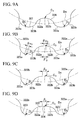
- each of the external teeth 311 of the inner rotor 310 is explained with reference to FIGS. 8A to 8D.
- the external teeth 311 of the inner rotor 310 are formed by alternately arranging tooth tips 312 and tooth spaces 313 in the circumferential direction.
- the epicycloid curve 316 (FIG. 8A) generated by the circumscribed-rolling circle Ai is equally divided at a midpoint A 3 thereof into two segments that are designated by outer tooth curve segments 312a and 312b, respectively.
- the outer tooth curve segments 312a and 312b are moved about the center Oi and along the circumference of the base circle Di by an amount of angle ⁇ i 3 so that a distance " ⁇ ' 3 " is ensured between the outer tooth curve segments 312a and 312b.
- the outer tooth curve segments 312a and 312b are moved in the direction of a tangent of the epicycloid curve 316 drawn at the midpoint A 3 thereof so that a distance " ⁇ 3 " is ensured between the outer tooth curve segments 312a and 312b.
- the separated ends of the outer tooth curve segments 312a and 312b are connected to each other by a complementary line 314 consisting of a straight line, and the obtained continuous curve is used as the profile of the tooth tip 312.
- the tooth tip 312 is formed using a continuous curve that includes the outer tooth curve segments 312a and 312b, which are separated from each other, and the complementary line 314 connecting the outer tooth curve segment 312a with the outer tooth curve segment 312b.
- the circumferential thickness of the tooth tip 312 of the inner rotor 310 is greater than a tooth tip which is formed just using the simple epicycloid curve 316 by an amount corresponding to the interposing complementary line 314.
- the complementary line 314, which connects the outer tooth curve segment 312a with the outer tooth curve segment 312b, is a straight line; however, the complementary line 314 may be a curve.
- the circumferential thickness of the tooth tip 312 is made to be greater than that of a conventional tooth tip as explained above, and on the other hand, in this embodiment, the width of the tooth space 313 is decreased, and tooth profiles are smoothly connected to each other over the entirety of the circumference.
- the hypocycloid curve 317 (FIG. 8A) generated by the inscribed-rolling circle Bi is equally divided at a midpoint B 3 thereof into two segments that are designated by curve segments 313a and 313b, respectively.
- the curve segments 313a and 313b are moved along the circumference of the base circle Di so that the ends of the curve segments 313a and 313b are respectively connected to the ends of the continuous curve that forms the tooth tip 312.
- the curve segments 313a and 313b overlap each other while intersecting each other at the midpoint B 3 .
- the curve segments 313a and 313b are moved in the direction of a tangent of the hypocycloid curve 317 drawn at the midpoint B 3 thereof so that the ends of the curve segments 313a and 313b are respectively connected to the ends of the continuous curve that forms the tooth tip 312.
- the curve segments 313a and 313b are smoothly connected to each other so as to form a continuous curve that defines the tooth profile of the tooth space 313.
- the circumferential width of the tooth space 313 is less than that of a tooth space which is formed just using the simple hypocycloid curve 317 by an amount corresponding to the complementary line 314 interposing in the tooth tip 312.
- the circumferential thickness of the tooth tip 312 is made to be greater and the circumferential width of the tooth space 313 is reduced when compared with the case in which tooth profiles are formed just using the epicycloid curve 316 and the hypocycloid curve 317 that are generated by the circumscribed-rolling circle Ai and the inscribed-rolling circle Bi. respectively.
- the distance " ⁇ 3 " between the outer tooth curve segment 312a and the outer tooth curve segment 312b is set so as to satisfy the following inequality: t 3 /4 ⁇ 3 , and more preferably, the distance " ⁇ 3 " is set so as to satisfy the following inequality: 2t 3 /5 ⁇ 3 .
- the distance " ⁇ 3 " between the outer tooth curve segment 312a and the outer tooth curve segment 312b is set so as to satisfy the following inequality: ⁇ 3 ⁇ 3t 3 /4. and more preferably, the distance " ⁇ 3 " is set so as to satisfy the following inequality: ⁇ 3 ⁇ 3t 3 /5.
- the internal teeth 321 of the outer rotor 320 are formed by alternately arranging tooth tips 322 and tooth spaces 323 in the circumferential direction.
- the hypocycloid curve 326 (FIG. 9A) generated by the inscribed-rolling circle Bo is equally divided at a midpoint C 3 thereof into two segments that are designated by inner tooth curve segments 322a and 322b, respectively.
- the inner tooth curve segments 322a and 322b are moved along the circumference of the base circle Do by an amount of angle ⁇ o 3 so that a distance " ⁇ ' 3 " is ensured between the inner tooth curve segments 322a and 322b.
- the inner tooth curve segments 322a and 322b are moved in the direction of a tangent of the hypocycloid curve 317 drawn at the midpoint C 3 thereof so that a distance " ⁇ 3 " is ensured between the outer tooth curve segments 312a and 312b.
- the separated ends of the inner tooth curve segments 322a and 322b are connected to each other by a complementary line 324 consisting of a straight line, and the obtained continuous curve is used as the profile of the tooth tip 322.
- the tooth tip 322 is formed using a continuous curve that includes the inner tooth curve segments 322a and 322b, which are separated from each other, and the complementary line 324 connecting the inner tooth curve segment 322a with the inner tooth curve segment 322b.
- the circumferential thickness of the tooth tip 322 is greater than a tooth tip which is formed just using the simple hypocycloid curve 326 by an amount corresponding to the interposing complementary line 324.
- the complementary line 324 which connects the inner tooth curve segment 322a with the inner tooth curve segment 322b, is a straight line; however, the complementary line 324 may be a curve.
- the circumferential thickness of the tooth tip 322 is made to be greater than that of a conventional tooth tip as explained above, and on the other hand, in this embodiment, the width of the tooth space 323 is decreased, and tooth profiles are smoothly connected to each other over the entirety of the circumference.
- the epicycloid curve 327 (FIG. 9A) generated by the circumscribed-rolling circle Ao is equally divided at a midpoint D 3 thereof into two segments that are designated by curve segments 323a and 323b, respectively.
- the curve segments 323a and 323b are moved along the circumference of the base circle Do so that the ends of the curve segments 323a and 323b are respectively connected to the ends of the continuous curve that forms the tooth tip 322.
- the curve segments 323a and 323b overlap each other while intersecting each other at the midpoint D 3 .
- the curve segments 323a and 323b are moved in the direction of a tangent of the epicycloid curve 327 drawn at the midpoint D 3 thereof so that the ends of the curve segments 323a and 323b are respectively connected to the ends of the continuous curve that forms the tooth tip 312.
- the curve segments 323a and 323b are smoothly connected to each other so as to form a continuous curve that defines the tooth profile of the tooth space 323.
- the circumferential width of the tooth space 323 is less than that of a tooth space which is formed just using the simple epicycloid curve 327 by an amount corresponding to the complementary line 324 interposing in the tooth tip 322.
- the circumferential thickness of the tooth tip 322 is made to be greater and the circumferential width of the tooth space 323 is reduced when compared with the case in which tooth profiles are formed just using the epicycloid curve 327 and the hypocycloid curve 326 that are generated by the circumscribed-rolling circle Ao and the inscribed-rolling circle Bo. respectively.
- the distance " ⁇ 3 " between the outer tooth curve segment 322a and the outer tooth curve segment 322b is set so as to satisfy the following inequality: t 3 /4 ⁇ 3 , and more preferably, the distance " ⁇ 3 " is set so as to satisfy the following inequality: 2t 3 /5 ⁇ 3 .
- the distance " ⁇ 3 " between the outer tooth curve segment 322a and the outer tooth curve segment 322b is set so as to satisfy the following inequality: ⁇ 3 ⁇ 3t 3 /4, and more preferably, the distance " ⁇ 3 " is set so as to satisfy the following inequality: ⁇ 3 ⁇ 3t 3 /5.
- the circumferential thicknesses of both tooth tip 312 of the inner rotor 310 and tooth tip 322 of the outer rotor 320 are increased when compared with conventional cases; however, the present invention is not limited to this, and other configurations may be employed in which one of the tooth tip 312 of the inner rotor 310 and tooth tip 322 of the outer rotor 320 is made thicker, and the tooth profile of the other tooth tip is formed using a cycloid curve without modification.
- the oil pump rotor assembly of the present invention may be formed using the base curves that satisfy the above relationships.
- the oil pump rotor assembly of the present invention may be formed using the base curves that satisfy the above relationships.
- FIGS. 10 to 12D A fourth embodiment of an oil pump rotor assembly according to the present invention will be explained below with reference to FIGS. 10 to 12D.
- each of the cells C is delimited at a front portion and at a rear portion as viewed in the direction of rotation of the inner rotor 410 and outer rotor 420 by contact regions between the external teeth 411 of the inner rotor 410 and the internal teeth 421 of the outer rotor 420, and is also delimited at either side portions by the casing 30, so that an independent fluid conveying chamber is formed.
- Each of the cells C moves while the inner rotor 410 and outer rotor 420 rotate, and the volume of each of the cells C cyclically increases and decreases so as to complete one cycle in a rotation.
- a suction port which communicates with one of the cells C whose volume increases gradually
- a discharge port which communicates with one of the cells C whose volume decreases gradually, and fluid drawn into one of the cells C through the suction port is transported as the rotors 410 and 420 rotate, and is discharged through the discharge port.
- a clearance that is formed between the apex of the tooth tip 412 of the inner rotor 410 and the apex of the tooth tip 422 of the outer rotor 420, which face each other on a line passing through the centers Oi and Oo of the rotors, is designated by a tip clearance.
- the size "t 4 " of this tip clearance is defined as the size of a tip clearance that is formed in a state in which the rotors 410 and 420 are disposed such that clearance between the tooth tip 412 of the inner rotor 410 and the tooth space 423 of the outer rotor 420, which engage each other on the line passing through the centers Oi and Oo at a diametrically opposing position, is zero.
- the center Oi of the inner rotor 410 and the center Oo of the outer rotor 420 are disposed to have an eccentric distance therebetween so that the same clearance t 4 /2 is formed between the tooth surfaces at two positions, located on the line passing through the centers Oi and Oo, at which the tooth surfaces face each other.
- the eccentric distance between the centers Oi and Oo is designated by "e”.
- the inner rotor 410 is mounted on a rotational axis so as to be rotatable about the center Oi, and the tooth profile of each of the external teeth 411 of the inner rotor 410 is formed using an epicycloid curve 416, which is generated by rolling a circumscribed-rolling circle Ai (whose diameter is ⁇ Ai) along the base circle Di (whose diameter is ⁇ Di) of the inner rotor 410 without slip, and using a hypocycloid curve 417, which is generated by rolling an inscribed-rolling circle Bi (whose diameter is ⁇ Bi.) along the base circle Di without slip.
- the outer rotor 420 is mounted so as to be rotatable about the center Oo, and the center thereof is positioned so as to have an offset (the eccentric distance is "e") from the center Oi.
- the tooth profile of each of the internal teeth 421 of the outer rotor 420 is formed using an epicycloid curve 427, which is generated by rolling a circumscribed-rolling circle Ao (whose diameter is ⁇ Ao) along the base circle Do (whose diameter is ⁇ Do) of the outer rotor 420 without slip, and using a hypocycloid curve 426, which is generated by rolling an inscribed-rolling circle Bo (whose diameter is ⁇ Bo) along the base circle Do without slip.
- each of the external teeth 411 of the inner rotor 410 is explained with reference to FIGS. 11A to 11D.
- the external teeth 411 of the inner rotor 410 are formed by alternately arranging tooth tips 412 and tooth spaces 413 in the circumferential direction.
- the epicycloid curve 416 (FIG. 11 A) generated by the circumscribed-rolling circle Ai is equally divided at a midpoint A 4 thereof into two segments that are designated by outer tooth curve segments 412a and 412b, respectively.
- the outer tooth curve segments 412a and 412b are moved in the direction of a tangent of the epicycloid curve 416 drawn at the midpoint A 4 thereof so that a distance " ⁇ 4 " is ensured between the outer tooth curve segments 412a and 412b.
- the outer tooth curve segments 412a and 412b are moved along the circumference of the base circle Di by an amount of angle ⁇ i 4 /2 so that a distance '' ⁇ 4 " is ensured between the outer tooth curve segments 412a and 412b.
- the separated ends of the outer tooth curve segments 412a and 412b are connected to each other by a complementary line 414 consisting of a straight line, and the obtained continuous curve is used as the profile of the tooth tip 412.
- the tooth tip 412 is formed using a continuous curve that includes the outer tooth curve segments 412a and 412b, which are separated from each other, and the complementary line 414 connecting the outer tooth curve segment 412a with the outer tooth curve segment 412b.
- the circumferential thickness of the tooth tip 412 of the inner rotor 410 is greater than a tooth tip which is formed just using the simple epicycloid curve 416 by an amount corresponding to the interposing complementary line 414.
- the complementary line 414 which connects the outer tooth curve segment 412a with the outer tooth curve segment 412b, is a straight line; however, the complementary line 414 may be a curve.
- the circumferential thickness of the tooth tip 412 is made to be greater than that of a conventional tooth tip as explained above, and on the other hand, in this embodiment, the width of the tooth space 413 is decreased, and tooth profiles are smoothly connected to each other over the entirety of the circumference.
- the hypocycloid curve 417 (FIG. 11A) generated by the inscribed-rolling circle Bi is equally divided at a midpoint B 4 thereof into two segments that are designated by curve segments 413a and 413b, respectively.
- the curve segments 413a and 413b are moved in the direction of a tangent of the hypocycloid curve 417 drawn at the midpoint B 4 thereof so that the ends of the curve segments 413a and 413b are respectively connected to the ends of the continuous curve that forms the tooth tip 412.
- the curve segments 413a and 413b overlap each other while intersecting each other at the midpoint B 4 .
- the curve segments 413a and 413b are moved along the circumference of the base circle Di so that the ends of the curve segments 413a and 413b are respectively connected to the ends of the continuous curve that forms the tooth tip 412.
- the curve segments 413a and 413b are smoothly connected to each other so as to form a continuous curve that defines the tooth profile of the tooth space 413.
- the circumferential width of the tooth space 413 is less than that of a tooth space which is formed just using the simple hypocycloid curve 417 by an amount corresponding to the complementary line 414 interposing in the tooth tip 412.
- the circumferential thickness of the tooth tip 412 is made to be greater and the circumferential width of the tooth space 413 is reduced when compared with the case in which tooth profiles are formed just using the epicycloid curve 416 and the hypocycloid curve 417 that are generated by the circumscribed-rolling circle Ai and the inscribed-rolling circle Bi, respectively.
- the distance " ⁇ 4 " between the outer tooth curve segment 412a and the outer tooth curve segment 412b is set so as to satisfy the following inequality: t 4 /4 ⁇ 4 , and more preferably, the distance " ⁇ 4 " is set so as to satisfy the following inequality: 2t 4 /5 ⁇ 4 .
- the distance " ⁇ 4 " between the outer tooth curve segment 412a and the outer tooth curve segment 412b is set so as to satisfy the following inequality: ⁇ 4 ⁇ 3t 4 /4, and more preferably, the distance " ⁇ 4 " is set so as to satisfy the following inequality: ⁇ 4 ⁇ 3t 4 /5.
- the internal teeth 421 of the outer rotor 420 are formed by alternately arranging tooth tips 422 and tooth spaces 423 in the circumferential direction.
- the hypocycloid curve 426 (FIG. 12A) generated by the inscribed-rolling circle Bo is equally divided at a midpoint C 4 thereof into two segments that are designated by inner tooth curve segments 422a and 422b. respectively.
- the inner tooth curve segments 422a and 422b are moved in the direction of a tangent of the hypocycloid curve 426 drawn at the midpoint C 4 thereof so that a distance " ⁇ ' 4 " is ensured between the outer tooth curve segments 412a and 412b.
- the inner tooth curve segments 422a and 422b are moved along the circumference of the base circle Do by an amount of angle ⁇ o 4 /2 so that a distance " ⁇ 4 " is ensured between the inner tooth curve segments 422a and 422b.
- the separated ends of the inner tooth curve segments 422a and 422b are connected to each other by a complementary line 424 consisting of a straight line, and the obtained continuous curve is used as the profile of the tooth tip 422.
- the tooth tip 422 is formed using a continuous curve that includes the inner tooth curve segments 422a and 422b, which are separated from each other, and the complementary line 424 connecting the inner tooth curve segment 422a with the inner tooth curve segment 422b.
- the circumferential thickness of the tooth tip 422 is greater than a tooth tip which is formed just using the simple hypocycloid curve 426 by an amount corresponding to the interposing complementary line 424.
- the complementary line 424 which connects the inner tooth curve segment 422a with the inner tooth curve segment 422b, is a straight line; however, the complementary line 424 may be a curve.
- the circumferential thickness of the tooth tip 422 is made to be greater than that of a conventional tooth tip as explained above, and on the other hand, in this embodiment, the width of the tooth space 423 is decreased, and tooth profiles are smoothly connected to each other over the entirety of the circumference.
- the epicycloid curve 427 (FIG. 12A) generated by the circumscribed-rolling circle Ao is equally divided at a midpoint D 4 thereof into two segments that are designated by curve segments 423a and 423b, respectively.
- the curve segments 423a and 423b are moved in the direction of a tangent of the epicycloid curve 427 drawn at the midpoint D 4 thereof so that the ends of the curve segments 423a and 423b are respectively connected to the ends of the continuous curve that forms the tooth tip 412, and so that the curve segments 423a and 423b overlap each other while intersecting each other at the midpoint D 4 .
- the curve segments 423a and 423b are moved along the circumference of the base circle Do so that the ends of the curve segments 423a and 423b are respectively connected to the ends of the continuous curve that forms the tooth tip 422.
- the curve segments 423a and 423b are smoothly connected to each other so as to form a continuous curve that defines the tooth profile of the tooth space 423.
- the circumferential width of the tooth space 423 is less than that of a tooth space which is formed just using the simple epicycloid curve 427 by an amount corresponding to the complementary line 424 interposing in the tooth tip 422.
- the circumferential thickness of the tooth tip 422 is made to be greater and the circumferential width of the tooth space 423 is reduced when compared with the case in which tooth profiles are formed just using the epicycloid curve 427 and the hypocycloid curve 426 that are generated by the circumscribed-rolling circle Ao and the inscribed-rolling circle Bo, respectively.
- the distance " ⁇ 4 " between the outer tooth curve segment 422a and the outer tooth curve segment 422b is set so as to satisfy the following inequality: t 4 /4 ⁇ 4 , and more preferably, the distance " ⁇ 4 " is set so as to satisfy the following inequality: 2t 4 /5 ⁇ 4 .
- the distance " ⁇ 4 " between the outer tooth curve segment 422a and the outer tooth curve segment 422b is set so as to satisfy the following inequality: ⁇ 4 ⁇ 3t 4 /4, and more preferably, the distance " ⁇ 4 " is set so as to satisfy the following inequality: ⁇ 4 ⁇ 3t 4 /5.
- the circumferential thicknesses of both tooth tip 412 of the inner rotor 410 and tooth tip 422 of the outer rotor 420 are increased when compared with conventional cases; however, the present invention is not limited to this, and other configurations may be employed in which one of the tooth tip 412 of the inner rotor 410 and tooth tip 422 of the outer rotor 420 is made thicker, and the tooth profile of the other tooth tip is formed using a cycloid curve without modification.
- the oil pump rotor assembly of the present invention may be formed using the base curves that satisfy the above relationships.
- the oil pump rotor assembly of the present invention may be formed using the base curves that satisfy the above relationships.
- the circumferential thickness of the tooth tip is made to be greater than that in the case of a conventional oil pump rotor assembly without changing the position of the tooth tip apex; therefore, an oil pump rotor assembly, which emits less noise, and which exhibits better mechanical performance when compared with a conventional oil pump rotor assembly, can be obtained.
- the clearance between the surfaces of the teeth of the inner and outer rotors may be made small; therefore, impacts between the rotors and hydraulic pulsation due to a large clearance between the tooth surfaces may be prevented, and an oil pump rotor assembly, which emits less noise, and which exhibits better mechanical performance when compared with a conventional oil pump rotor assembly, can be obtained.
Landscapes
- Engineering & Computer Science (AREA)
- Mechanical Engineering (AREA)
- General Engineering & Computer Science (AREA)
- Rotary Pumps (AREA)
Applications Claiming Priority (8)
| Application Number | Priority Date | Filing Date | Title |
|---|---|---|---|
| JP2002209838 | 2002-07-18 | ||
| JP2002209838 | 2002-07-18 | ||
| JP2002209839 | 2002-07-18 | ||
| JP2002209836 | 2002-07-18 | ||
| JP2002209839 | 2002-07-18 | ||
| JP2002209837 | 2002-07-18 | ||
| JP2002209836 | 2002-07-18 | ||
| JP2002209837 | 2002-07-18 |
Publications (3)
| Publication Number | Publication Date |
|---|---|
| EP1382852A2 true EP1382852A2 (de) | 2004-01-21 |
| EP1382852A3 EP1382852A3 (de) | 2006-09-06 |
| EP1382852B1 EP1382852B1 (de) | 2009-01-14 |
Family
ID=29783300
Family Applications (1)
| Application Number | Title | Priority Date | Filing Date |
|---|---|---|---|
| EP03015651A Expired - Lifetime EP1382852B1 (de) | 2002-07-18 | 2003-07-17 | Innenläuferzahnradölpumpe |
Country Status (7)
| Country | Link |
|---|---|
| US (1) | US7118359B2 (de) |
| EP (1) | EP1382852B1 (de) |
| KR (1) | KR100525608B1 (de) |
| CN (1) | CN1475672A (de) |
| DE (1) | DE60325808D1 (de) |
| ES (1) | ES2318074T3 (de) |
| MY (1) | MY141586A (de) |
Cited By (1)
| Publication number | Priority date | Publication date | Assignee | Title |
|---|---|---|---|---|
| EP2206923A4 (de) * | 2008-08-08 | 2014-10-29 | Sumitomo Electric Sintered Aly | Rotor für eine innenzahnradpumpe und innenzahnradpumpe mit dem rotor |
Families Citing this family (5)
| Publication number | Priority date | Publication date | Assignee | Title |
|---|---|---|---|---|
| MY138173A (en) * | 2003-08-12 | 2009-05-29 | Diamet Corp | Oil pump rotor assembly |
| JP4889981B2 (ja) * | 2005-08-31 | 2012-03-07 | 株式会社ダイヤメット | 内接型ギヤポンプ |
| EP1927752B1 (de) | 2005-09-22 | 2018-09-12 | Aisin Seiki Kabushiki Kaisha | Ölpumpenrotor |
| WO2008111270A1 (ja) * | 2007-03-09 | 2008-09-18 | Aisin Seiki Kabushiki Kaisha | オイルポンプロータ |
| JP5692034B2 (ja) * | 2011-12-14 | 2015-04-01 | 株式会社ダイヤメット | オイルポンプロータ |
Citations (1)
| Publication number | Priority date | Publication date | Assignee | Title |
|---|---|---|---|---|
| JPH05256268A (ja) | 1992-01-15 | 1993-10-05 | Siegfried A Eisenmann | 歯車式機械 |
Family Cites Families (12)
| Publication number | Priority date | Publication date | Assignee | Title |
|---|---|---|---|---|
| DE330610C (de) | 1918-06-07 | 1920-12-18 | Josef Lehne | Schrauben- oder Pfeilzahnradpumpe |
| GB233423A (en) | 1924-02-07 | 1925-05-07 | Hill Compressor & Pump Co Inc | Improvements in or relating to rotary pumps or the like |
| US3982445A (en) * | 1975-09-02 | 1976-09-28 | Rouverol William S | High torque gearing |
| DE3141193A1 (de) | 1980-10-17 | 1982-05-19 | Hobourn-Eaton Ltd., Strood, Rochester, Kent | Pumpe |
| JPS5979083A (ja) * | 1982-10-27 | 1984-05-08 | Sumitomo Electric Ind Ltd | 回転ポンプ用ロ−タ− |
| US5226798A (en) * | 1989-11-17 | 1993-07-13 | Eisenmann Siegfried A | Gear ring pump for internal-combustion engines and automatic transmissions |
| GB9010686D0 (en) | 1990-05-12 | 1990-07-04 | Concentric Pumps Ltd | Gerotor pumps |
| US5163826A (en) * | 1990-10-23 | 1992-11-17 | Cozens Eric E | Crescent gear pump with hypo cycloidal and epi cycloidal tooth shapes |
| DE4311165C2 (de) * | 1993-04-05 | 1995-02-02 | Danfoss As | Hydraulische Maschine |
| DE4311168C2 (de) * | 1993-04-05 | 1995-01-12 | Danfoss As | Hydraulische Maschine |
| MY120206A (en) * | 1996-01-17 | 2005-09-30 | Diamet Corp | Oil pump rotor |
| US6077059A (en) * | 1997-04-11 | 2000-06-20 | Mitsubishi Materials Corporation | Oil pump rotor |
-
2003
- 2003-07-16 MY MYPI20032671A patent/MY141586A/en unknown
- 2003-07-16 US US10/622,107 patent/US7118359B2/en not_active Expired - Lifetime
- 2003-07-17 DE DE60325808T patent/DE60325808D1/de not_active Expired - Lifetime
- 2003-07-17 ES ES03015651T patent/ES2318074T3/es not_active Expired - Lifetime
- 2003-07-17 CN CNA031787444A patent/CN1475672A/zh active Pending
- 2003-07-17 EP EP03015651A patent/EP1382852B1/de not_active Expired - Lifetime
- 2003-07-18 KR KR10-2003-0049385A patent/KR100525608B1/ko not_active Expired - Fee Related
Patent Citations (1)
| Publication number | Priority date | Publication date | Assignee | Title |
|---|---|---|---|---|
| JPH05256268A (ja) | 1992-01-15 | 1993-10-05 | Siegfried A Eisenmann | 歯車式機械 |
Cited By (1)
| Publication number | Priority date | Publication date | Assignee | Title |
|---|---|---|---|---|
| EP2206923A4 (de) * | 2008-08-08 | 2014-10-29 | Sumitomo Electric Sintered Aly | Rotor für eine innenzahnradpumpe und innenzahnradpumpe mit dem rotor |
Also Published As
| Publication number | Publication date |
|---|---|
| DE60325808D1 (de) | 2009-03-05 |
| EP1382852B1 (de) | 2009-01-14 |
| MY141586A (en) | 2010-05-14 |
| ES2318074T3 (es) | 2009-05-01 |
| CN1475672A (zh) | 2004-02-18 |
| KR100525608B1 (ko) | 2005-11-02 |
| US7118359B2 (en) | 2006-10-10 |
| KR20040010263A (ko) | 2004-01-31 |
| EP1382852A3 (de) | 2006-09-06 |
| US20040067151A1 (en) | 2004-04-08 |
Similar Documents
| Publication | Publication Date | Title |
|---|---|---|
| US8360762B2 (en) | Oil pump rotor | |
| KR101029624B1 (ko) | 내접 기어식 펌프 및 그 펌프의 내측 회전자 | |
| US8096795B2 (en) | Oil pump rotor | |
| KR101263037B1 (ko) | 신규의 회전자 세트를 갖는 초승달형 기어 펌프 | |
| US6887056B2 (en) | Oil pump rotor | |
| EP1559912B1 (de) | Ölpumpenrotoreinheit mit innenverzahnung | |
| EP1382852B1 (de) | Innenläuferzahnradölpumpe | |
| US6929458B2 (en) | Oil pump rotor | |
| US7476093B2 (en) | Oil pump rotor assembly | |
| US7588429B2 (en) | Oil pump rotor assembly | |
| JP2003322088A (ja) | オイルポンプロータ | |
| JPH11264381A (ja) | オイルポンプロータ | |
| JP4393943B2 (ja) | オイルポンプロータ | |
| JP4255768B2 (ja) | オイルポンプロータ | |
| JP4255770B2 (ja) | オイルポンプロータ | |
| JP2003322089A (ja) | オイルポンプロータ | |
| JP4255771B2 (ja) | オイルポンプロータ | |
| JP4255769B2 (ja) | オイルポンプロータ | |
| JP3132632B2 (ja) | 内接型オイルポンプロータ |
Legal Events
| Date | Code | Title | Description |
|---|---|---|---|
| PUAI | Public reference made under article 153(3) epc to a published international application that has entered the european phase |
Free format text: ORIGINAL CODE: 0009012 |
|
| AK | Designated contracting states |
Kind code of ref document: A2 Designated state(s): AT BE BG CH CY CZ DE DK EE ES FI FR GB GR HU IE IT LI LU MC NL PT RO SE SI SK TR |
|
| AX | Request for extension of the european patent |
Extension state: AL LT LV MK |
|
| RAP1 | Party data changed (applicant data changed or rights of an application transferred) |
Owner name: MITSUBISHI MATERIALS PMG CORPORATION |
|
| PUAL | Search report despatched |
Free format text: ORIGINAL CODE: 0009013 |
|
| AK | Designated contracting states |
Kind code of ref document: A3 Designated state(s): AT BE BG CH CY CZ DE DK EE ES FI FR GB GR HU IE IT LI LU MC NL PT RO SE SI SK TR |
|
| AX | Request for extension of the european patent |
Extension state: AL LT LV MK |
|
| 17P | Request for examination filed |
Effective date: 20061218 |
|
| AKX | Designation fees paid |
Designated state(s): DE ES FR GB HU IT |
|
| 17Q | First examination report despatched |
Effective date: 20071106 |
|
| GRAP | Despatch of communication of intention to grant a patent |
Free format text: ORIGINAL CODE: EPIDOSNIGR1 |
|
| GRAS | Grant fee paid |
Free format text: ORIGINAL CODE: EPIDOSNIGR3 |
|
| GRAA | (expected) grant |
Free format text: ORIGINAL CODE: 0009210 |
|
| AK | Designated contracting states |
Kind code of ref document: B1 Designated state(s): DE ES FR GB HU IT |
|
| REG | Reference to a national code |
Ref country code: GB Ref legal event code: FG4D |
|
| REF | Corresponds to: |
Ref document number: 60325808 Country of ref document: DE Date of ref document: 20090305 Kind code of ref document: P |
|
| REG | Reference to a national code |
Ref country code: ES Ref legal event code: FG2A Ref document number: 2318074 Country of ref document: ES Kind code of ref document: T3 |
|
| REG | Reference to a national code |
Ref country code: HU Ref legal event code: AG4A Ref document number: E005194 Country of ref document: HU |
|
| PLBE | No opposition filed within time limit |
Free format text: ORIGINAL CODE: 0009261 |
|
| STAA | Information on the status of an ep patent application or granted ep patent |
Free format text: STATUS: NO OPPOSITION FILED WITHIN TIME LIMIT |
|
| 26N | No opposition filed |
Effective date: 20091015 |
|
| PG25 | Lapsed in a contracting state [announced via postgrant information from national office to epo] |
Ref country code: HU Free format text: LAPSE BECAUSE OF NON-PAYMENT OF DUE FEES Effective date: 20090718 |
|
| REG | Reference to a national code |
Ref country code: FR Ref legal event code: CA Ref country code: FR Ref legal event code: CD |
|
| REG | Reference to a national code |
Ref country code: ES Ref legal event code: PC2A |
|
| PGFP | Annual fee paid to national office [announced via postgrant information from national office to epo] |
Ref country code: ES Payment date: 20100629 Year of fee payment: 8 |
|
| PGFP | Annual fee paid to national office [announced via postgrant information from national office to epo] |
Ref country code: DE Payment date: 20100729 Year of fee payment: 8 Ref country code: FR Payment date: 20100806 Year of fee payment: 8 |
|
| PGFP | Annual fee paid to national office [announced via postgrant information from national office to epo] |
Ref country code: GB Payment date: 20100728 Year of fee payment: 8 |
|
| PG25 | Lapsed in a contracting state [announced via postgrant information from national office to epo] |
Ref country code: IT Free format text: LAPSE BECAUSE OF NON-PAYMENT OF DUE FEES Effective date: 20100717 |
|
| PGFP | Annual fee paid to national office [announced via postgrant information from national office to epo] |
Ref country code: IT Payment date: 20100728 Year of fee payment: 8 |
|
| PGRI | Patent reinstated in contracting state [announced from national office to epo] |
Ref country code: IT Effective date: 20110616 |
|
| GBPC | Gb: european patent ceased through non-payment of renewal fee |
Effective date: 20110717 |
|
| REG | Reference to a national code |
Ref country code: FR Ref legal event code: ST Effective date: 20120330 |
|
| PG25 | Lapsed in a contracting state [announced via postgrant information from national office to epo] |
Ref country code: DE Free format text: LAPSE BECAUSE OF NON-PAYMENT OF DUE FEES Effective date: 20120201 Ref country code: FR Free format text: LAPSE BECAUSE OF NON-PAYMENT OF DUE FEES Effective date: 20110801 |
|
| REG | Reference to a national code |
Ref country code: DE Ref legal event code: R119 Ref document number: 60325808 Country of ref document: DE Effective date: 20120201 |
|
| PG25 | Lapsed in a contracting state [announced via postgrant information from national office to epo] |
Ref country code: IT Free format text: LAPSE BECAUSE OF NON-PAYMENT OF DUE FEES Effective date: 20110717 |
|
| PG25 | Lapsed in a contracting state [announced via postgrant information from national office to epo] |
Ref country code: GB Free format text: LAPSE BECAUSE OF NON-PAYMENT OF DUE FEES Effective date: 20110717 |
|
| REG | Reference to a national code |
Ref country code: ES Ref legal event code: FD2A Effective date: 20130604 |
|
| PG25 | Lapsed in a contracting state [announced via postgrant information from national office to epo] |
Ref country code: ES Free format text: LAPSE BECAUSE OF NON-PAYMENT OF DUE FEES Effective date: 20110718 |