EP1382954A2 - Méthode et appareil pour mesurer les caractéristiques optiques des lentilles de lunettes. - Google Patents
Méthode et appareil pour mesurer les caractéristiques optiques des lentilles de lunettes. Download PDFInfo
- Publication number
- EP1382954A2 EP1382954A2 EP03015563A EP03015563A EP1382954A2 EP 1382954 A2 EP1382954 A2 EP 1382954A2 EP 03015563 A EP03015563 A EP 03015563A EP 03015563 A EP03015563 A EP 03015563A EP 1382954 A2 EP1382954 A2 EP 1382954A2
- Authority
- EP
- European Patent Office
- Prior art keywords
- lens
- frame
- measurement
- spectacle
- pair
- Prior art date
- Legal status (The legal status is an assumption and is not a legal conclusion. Google has not performed a legal analysis and makes no representation as to the accuracy of the status listed.)
- Withdrawn
Links
Images


Classifications
-
- G—PHYSICS
- G01—MEASURING; TESTING
- G01M—TESTING STATIC OR DYNAMIC BALANCE OF MACHINES OR STRUCTURES; TESTING OF STRUCTURES OR APPARATUS, NOT OTHERWISE PROVIDED FOR
- G01M11/00—Testing of optical apparatus; Testing structures by optical methods not otherwise provided for
- G01M11/02—Testing optical properties
- G01M11/0207—Details of measuring devices
- G01M11/0214—Details of devices holding the object to be tested
-
- G—PHYSICS
- G01—MEASURING; TESTING
- G01M—TESTING STATIC OR DYNAMIC BALANCE OF MACHINES OR STRUCTURES; TESTING OF STRUCTURES OR APPARATUS, NOT OTHERWISE PROVIDED FOR
- G01M11/00—Testing of optical apparatus; Testing structures by optical methods not otherwise provided for
- G01M11/02—Testing optical properties
- G01M11/0221—Testing optical properties by determining the optical axis or position of lenses
-
- G—PHYSICS
- G01—MEASURING; TESTING
- G01M—TESTING STATIC OR DYNAMIC BALANCE OF MACHINES OR STRUCTURES; TESTING OF STRUCTURES OR APPARATUS, NOT OTHERWISE PROVIDED FOR
- G01M11/00—Testing of optical apparatus; Testing structures by optical methods not otherwise provided for
- G01M11/02—Testing optical properties
- G01M11/0228—Testing optical properties by measuring refractive power
- G01M11/0235—Testing optical properties by measuring refractive power by measuring multiple properties of lenses, automatic lens meters
Definitions
- This invention relates to a method of measuring optical characteristics of spectacle lenses and a lens meter in which it is possible to measure refraction characteristics of right and left lenses of a pair of spectacles individually by means of two measurement optical systems.
- a conventionally known lens meter includes: upper and lower accommodating protrusions provided on upper and lower portions of a front surface of a main body case and vertically spaced apart from each other; a lens rest provided on an upper surface of the lower accommodating protrusion; a lens table extending horizontally and mounted to the main body case so as to be movable forwards and backwards with respect to the lens rest; a nose pad support member mounted to the lens table so as to be horizontally and vertically movable; and a measurement optical system for measuring refraction characteristics of a lens placed on the lens rest.
- the measurement optical system is equipped with an illumination optical system provided in the main body case and the upper accommodating protrusion and a light receiving optical system provided in the lower accommodating protrusion and the main body case.
- the nose pads of a pair of spectacles are supported by the nose pad support member, and right and left lens rims of a spectacle frame are held in contact with a front surface of the lens table.
- the nose pad support member is moved horizontally and vertically, and the lens table is moved forwards and backwards to bring one of the right and left lenses into contact with the lens rest, measuring the refraction characteristics of that lens by the measurement optical system.
- the spectacle frame is moved in the same way as described above so as to bring the other lens into contact with the lens rest.
- the above-described conventional lens meter has a problem in that, when performing measurement on the right and left spectacle lenses, it is necessary to bring the lenses one by one into contact with a single lens rest, which is a bother.
- a lens meter equipped with a pair of optical systems for performing measurement on the right and left lenses of a pair of spectacles.
- a lens meter to accurately measure the refraction characteristics of the spectacle lenses, it is necessary, in the measurement optical axis of each light receiving optical system, for the distance between the lower surface of the lens and the light receiving means of the light receiving optical system to be fixed.
- a shaft-shaped lens rest is provided at some midpoint of the optical path of each of the right and left measurement optical systems to make the distance between the lower surface of the lens and the light receiving means of the light receiving optical system fixed.
- a spectacle lens optical characteristic measuring method including: point-supporting left and right spectacle lenses of a pair of spectacles respectively by lens rests at some midpoints of optical paths of a pair of left and right measurement optical systems; retaining a spectacle frame for the spectacle lenses from front and rear sides by a pair of frame retaining members; pressing the spectacle lenses in this state against the lens rests by a lens presser member to correct the way the spectacle frame is retained by the frame retaining members; retracting the lens presser members from the optical paths of the measurement optical systems; measuring measurement beams around the lens rests transmitted through the spectacle lenses by the measurement optical systems; and obtaining optical characteristics of the spectacle lenses on the basis of a measurement signal from the measurement optical systems by a computation control circuit.
- a lens meter including: a pair of left and right lens rests capable of point-supporting left and right lenses of a pair of spectacles; a pair of frame retaining members capable of holding a spectacle frame of the pair of spectacles whose lenses are supported by the lens rests from front and rear sides; lens presser members for pressing the spectacle lenses supported by the lens rests against the lens rests; a pair of left and right measurement optical systems for measuring optical characteristics of the spectacle lenses supported by the lens rests on the basis of measurement beams passing a periphery of the lens rests; and a computation control circuit which controls the measurement optical systems to cause it to execute the measurement and which obtains the optical characteristics of the spectacle lenses on the basis of measurement signals from the measurement optical systems, the lens meter further including presser member driving means for moving the lens presser members from pressing positions where they press the spectacle lenses against the lens rests and to retracted positions where they are retracted from the
- the pair of frame retaining members have opposing surfaces tapered so as to be inclined respectively downwardly.
- the lens meter further includes frame detecting means provided between the pair of frame retaining members and adapted to detect the spectacle frame of the spectacle lenses supported by the lens rests and retaining member driving means for driving the pair of frame retaining members so as to move them toward and away from each other, and in the lens meter, the computation control circuit operationally controls the retaining member driving means upon detection of the spectacle frame by the frame detecting means so as to move the pair of frame retaining members toward each other to cause them to hold the spectacle frame, and operationally controls the presser member driving means so as to move the lens presser members to the pressing positions to press the spectacle lenses against the lens rests before moving the lens presser members to the retracted positions.
- the frame detecting means is further equipped with a nose pad support member for supporting nose pads of the pair of spectacles which is arranged between the pair of left and right measurement optical systems and movable in the back and forth direction, biasing means for forwardly biasing the nose pad support member, and a detecting switch which detects backward movement of the nose pad support member against the biasing force of the biasing means.
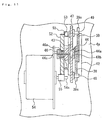
- Fig. 1 is a front view of a lens meter according to the present invention
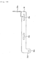
- Fig. 2 is a right-hand side view of Fig. 1.
- reference numeral 1 indicates an apparatus main body (main body case) .
- the apparatus main body 1 is composed of an upper casing 2, a lower casing 3, and a joint casing 4 joining the upper casing 2 and the lower casing 3 to each other, and has a substantially U-shaped configuration in side view as shown in Fig. 2.
- a space defined between the upper casing 2 and the lower casing 3 constitutes a setting space 6 for a pair of spectacles 5 shown in Fig. 5.
- the joint casing 4 is composed of a front wall 4a and a rear, detachable casing portion 4b.
- the pair of spectacles 5 have a spectacle frame MF, spectacle lenses LL and LR fitted in the left and right lens rims LF and RF of the spectacle frame MF, a bridge B connecting the left and right lens rims LF and RF, nose pads NP provided, for example, on the left and right lens rims LF and RF, and temples LT and RT provided on the left and right lens rims LF and RF.
- the lower casing 3 has an upper wall 7 having openings 8L and 8R at left and right portions of the upper wall 7, as shown in Fig. 1.
- This lower casing 3 is divided into left and right spaces (chambers) 3L and 3R by a partition 3a arranged at its horizontal center.
- the apparatus main body 1 has a pair of left and right measurement optical systems 9L and 9R as shown in Fig. 5.
- the measurement optical system 9L has a light emitting optical system (illumination optical system) 10L contained in the upper casing 2 and a light receiving optical system 11L contained in the lower casing 3.
- the light emitting optical system 10L is equipped with LEDs 12 and 13 serving as the light source for measurement beam proj ection, a dichroic mirror 14L, a reflection mirror 15, and a collimating lens 16.
- the LED 12 emits infrared light
- the LED 13 emits red light (with a wavelength of 630 nm).
- the dichroic mirror 14L reflects the infrared light from the LED 12, transmitting only the red light from the LED 13.
- the collimating lens 16 serves to convert divergent light emitted from the LEDs 12 and 13 into parallel beams as the measurement beams. Of the reflection mirror 15, the left half thereof is used.
- the light receiving optical system 11L has a Hartmann pattern plate 17, a field lens 18 having a screen 18a on its upper surface, reflection mirrors 19, 20, and 21, an optical path synthesizing prism 22, an image formation lens 23, and a CCD (photo receptor, light receiving means) 24.
- the pattern plate 17 is equipped with a multitude of light transmission portions (not shown) arranged in matrix.
- a pin-like lens rest shaft (lens rest) 17a protrudes upwards as a reference pin.
- This lens rest shaft 17a has a semi-spherical upper end portion, and is arranged such that its axis is in alignment with the optical axis of the measurement optical system 9L.
- the measurement optical system 9R has a light emitting optical system (illumination optical system) 10R contained in the upper casing 2 and a light receiving optical system 11R contained in the lower casing 3.
- the light emitting optical system 10R is equipped with LEDs 25 and 26 serving as the light source for measurement beam projection, a dichroic mirror 14R, a reflection mirror 15, and a collimating lens 27.
- the LED 25 emits infrared light
- the LED 26 emits red light (with a wavelength of 630 nm) .
- the above-mentioned dichroic mirror 14R reflects the infrared light from the LED 25, transmitting only the red light from the LED 26.
- the collimating lens 27 serves to convert divergent light emitted from the LEDs 25 and 26 into parallel beams as the measurement beams. Of the reflection mirror 15, the right half thereof is used.
- the light receiving optical system 11R has a Hartmann pattern plate 28, a field lens 29 having a screen 29a on its upper surface, reflection mirrors 30 and 31, an optical path synthesizing prism 22, an image formation lens 23, and a CCD (photo receptor, light receiving means) 24.
- the pattern plate 28 is equipped with a multitude of light transmission portions (not shown) arranged in a matrix-like fashion.
- a pin-like lens rest shaft (lens rest) 28a protrudes upwards as a reference pin.
- This lens rest shaft 28a has a semi-spherical upper end portion, and is arranged such that its axis is in alignment with the optical axis OR of the measurement optical system 9R.
- the apparatus main body 1 is equipped with a frame retaining mechanism constructed as follows for retaining the frame MF of the pair of spectacles 5 when the left and right spectacle lenses LL and RL are supported by the lens rest shafts 17a and 28a. Further, as shown in Fig. 9, in the horizontal central portions 32 and 33 of the front edge portion and the rear edge portion of the upper wall 7, there are formed slits 34 and 35 extending back and forth along the partition 3a.
- this frame retaining mechanism has a pair of frame retaining plates 36 and 37 serving as frame retaining members (lens retaining members, lens rim retaining members) respectively arranged on the front edge portion and the rear edge portion of the upper wall 7 so as to extend in the horizontal direction. As shown in Figs. 2, 6, and 8, these frame retaining plates 36 and 37 have opposing surfaces 36a and 37a formed as tapered surfaces slightly inclined downwards.
- this frame retaining mechanism (lens rim retaining mechanism) has a pair of linkage plates (movement members, slide plates) 38 and 39 arranged inside the lower casing 3 (see Figs. 8, 11, and 12). These linkage plates 38 and 39 are arranged so as to extend back and forth along the upper portion of one side surface of the partition 3a.
- the linkage plate 38 has, at one end thereof, a mounting member 38a protruding upwards as shown in Figs. 8 and 14, slits 38b and 38c formed so as to be horizontally spaced apart from each other as shown in Figs. 8, 12, and 14, an engagement member 38d protruding downwards from the other end thereof, and an engagement cutout 38e formed in the engagement member 38d so as to be directed downwards.
- the mounting member 38a protrudes beyond the upper wall 7 through the slit 34 and is mounted to the frame retaining plate 36.
- the linkage plate 39 has a mounting member 39a protruding upwards from its longitudinal center, slits 39b and 39c formed at one end and in the intermediate portion thereof, an engagement member 39d protruding upwards from the other end thereof, and an engagement cutout 39e formed in the engagement member 39d so as to be directed upwards.
- the mounting member 39a protrudes beyond the upper wall 7 through the slit 35 and is mounted to the frame retaining plate 37.
- a guide screw 40 is passed through the slits 38b and 39b of the linkage plates 38 and 39, respectively. After that, a forward end portion of the guide screw 40 threadedly engaged with the partition 3a. Further, a guide screw 41 is passed through the slits 38c and 39c of the linkage plates 38 and 39, respectively. After that, a forward end portion of the guide screw 41 threadedly engaged with the partition 3a. These guide screws 40 and 41 join (engage) the linkage plates 38 and 39 so as to allow longitudinally relative sliding displacement.
- the frame retaining mechanism has an opening 42 formed in the front wall 4a of the joint casing 4 in correspondence with the upper portion of the lower casing 3 and the position of the partition 3a, a support member 43 protruding rearwards (into the lower casing 3) at the side edge of the opening 42, and a support screw 44 mounted to the support member 43.
- this support screw 44 has a head portion 44a situated on the opening 42 side, a large diameter portion 44b connected to the head portion 44a, and a threaded portion 44c connected to the large diameter portion 44b. And, the support screw 44 is mounted to the support member 43 by threadedly engaging the threaded portion 44c with the support member 43. Further, the threaded portion 44c extends through the support member 43 to protrude on the side opposite to the opening 42. Further, as shown in Fig. 11, a ring-like spacer 45 is attached to the protruding portion of the threaded portion 44c, and a nut 46 is threadedly engaged therewith. This nut 46 has a small diameter portion 46a on the spacer 45 side, and secures the spacer 45 to the support member 43.
- the frame retaining mechanism has a rotary plate (connection member) 47 rotatably retained by the large diameter portion 44b, engagement pins 48 and 49 mounted to the linkage plate 38, 39 side portions of the rotary plate 47 at an interval of 180 degrees, and an engagement pin 50 protruding on the support member 43 side. And, the engagement pins 48 and 49 are engaged with the engagement cutouts 38e and 39e of the linkage plates 38 and 39.
- a coil spring 51 is provided between the base portions of the mounting members 38a and 39a of the linkage plates 38 and 39, and the coil spring 51 elastically biases the linkage plates 38 and 39 such that the frame retaining plates 36 and 37 are brought close to each other.
- a gear 52 is rotatably supported by a small-diameter axial portion 46a of the nut 46 through the intermediation of a bearing, and integrally provided on the side surface of the gear 52 is an engagement protrusion 53 adapted to be circumferentially engaged with the engagement pin 50.
- a drive motor (driving means) 54 consisting of a pulse motor or the like mounted to the front wall 4a of the joint casing 4.
- a pinion 55 mounted to an output shaft 54a of this drive motor 54 is a pinion 55 in mesh with the gear 52.
- limit switch 56 mounted to the partition 3a is limit switch 56 as a position detecting means for detecting the movement stop position of the linkage plate 38 when the interval between the frame retaining plates 36 and 37 is maximum (see Fig. 8).
- a semi-axial nose pad support member 57 is arranged on the upper wall 7 so as to be situated between the openings 8L and 8R and between the frame retaining plates 36 and 37.
- the nose pad support member 57 extends vertically and is semi-circular in plan configuration.
- a support shaft 58 protrudes from the lower end of the nose pad support member 57 (See Fig. 10) .
- a slit 59 situated between the openings 8L and 8R and extending in the back and forth direction.
- the support shaft 58 protruding from the lower end of the nose pad support member 57 is inserted into the slit 59.
- support plates 60 and 61 extending along the slit 59 are arranged, and the support shaft 58 extends through the support plates 60 and 61.
- a spacer cylinder 62 fitted onto the support shaft 58 is provided between the support plates 60 and 61, and a fixation nut 63 is threadedly engaged with the lower end portion of the support shaft 58.
- the fixation nut 63 serves to fix the support plates 60 and 61 and the spacer cylinder 62 integrally to the nose pad support member 57.
- the spacer 62 is arranged inside the slit 59 so as to be longitudinally movable and laterally immovable. Further, the length of the spacer cylinder 62 is formed so as to be slightly larger than the thickness of the upper wall 7, and the support plates 60 and 61 are movable along the plate surface of the upper wall 7. The support shaft 58 and the support plates 60 and 61 make no relative rotation.
- a coil spring S is provided between a spring hook protrusion 61a of the support plate 61 and a spring hook protrusion 3b of the partition 3a, and the coil spring S biases the support plates 60 and 61 and the nose rest support member 57 toward the frame retaining member 36.
- a microswitch 64 is mounted as movement detecting means to the partition 3a in correspondence with the position of the frame retaining plate 37 side end 61b of the support plate 61.
- a lens presser mechanism 65 as the lens presser means is provided in the front wall 4a of the joint casing 4.
- the lens presser means 65 has rotation shafts 66L and 66R provided above the frame retaining plate 37 and respectively to the right and left side portions of the front wall 4a so as to be rotatable.
- the rotation shafts 66L and 66R protrude from the front wall 4a toward the user side so as to be parallel to each other.
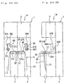
- the lens presser mechanism 65 has L-shaped arms 67L and 67R respectively fixed to the rotation shafts 66L and 66R, a pair of lens presser shafts 68L mounted to the forward end portion of the arm 67L (see Fig. 19(B)), and a pair of lens presser shafts 68R mounted to the forward end portion of the arm 67R (see Fig. 19(B)).
- each pair of the lens presser shafts 68L and 68R is visible, whereas in the right-hand side view of the lens meter 1 of Fig. 19(A), a pair of lens presser shafts 68R are visible as shown in Fig. 19 (B) .
- the pair of lens presser shafts 68L are situated so as to overlap the pair of lens presser shafts 68R.
- the lens presser shafts 68L and 68R will be described collectively.
- the forward end portions of the lens presser shafts 68L and 68R are formed in a pin-like configuration.
- the lens presser shafts 68L (68R) are arranged back and forth in the axis of the lens rest 17a (28a) serving as the reference pin, i.e., in the optical axis OL (OR).
- the lens presser mechanism 65 has substantially sector-shaped rotation plates 69L and 69R respectively fixed to rotation shafts 66L and 66R inside the joint casing 4, narrow engagement members 70L and 70R connected to the lower edge portions of the rotation plates 69L and 69R, spring engagement portions 71L and 71R provided at the lower edges of the rotation plates 69L and 69R, spring engagement portions 72L and 72R situated below the spring engagement portions 71L and 71R and protruding from the front wall 4a, an extension coil spring 73L provided between the spring engagement portions 71L and 72L, and an extension coil spring 73R provided between the spring engagement portions 71R and 72R.
- the lens presser mechanism 65 has a drive motor 74 consisting of a pulse motor or the like mounted to the upper portion of the front wall 4a inside the joint casing 4.
- the drive motor 74 has an output shaft 74a vertically oriented and arranged at the lateral center of the joint casing 4.
- a pinion 75 is mounted to the output shaft 74a.
- an L-shaped bracket 76 is mounted to the front wall 4a so as to be situated below the drive motor 74.
- the upper end portion of a feed screw 77 vertically extending along the front wall 4a is retained by the bracket 76 so as to be rotatable and vertically immovable.
- a gear 78 mounted to the upper end portion of the feed screw 77 is a gear 78 in mesh with the pinion 75.
- This feed screw 77 is arranged at the lateral center of the joint casing 4, and an ascent/descent member 79 is threadedly engaged with the screw portion 77a in the lower portion of the feed screw 77.
- a flange 79a extending horizontally in Fig. 7 protrudes from the lower end portion of the ascent/descent member 79 toward the front wall 4a.
- This flange 79a is in contact with the front wall 4a, and slides vertically with respect to the front wall 4a while in contact with the front wall 4a, due to ascent/descent of the ascent/descent member 79 .
- the forward end portions of the engagement members 70L and 70R are held in contact with the flange 79a by the elastic force of extension springs 73L and 73R.
- the output (measurement signal) of the above-mentioned CCD 24 is input to the computation control circuit (computation control means) 80 of Fig. 5, and the limit switch 56 and the microswitch 64 are connected to the computation control circuit 80. Further, the computation control circuit 80 performs lighting control on the LEDs 12, 13, 25, and 26, to control the drive motors 54 and 74. Further, a measurement start switch Sa is connected to the computation control circuit 80.
- the engagement protrusion 53 of the gear 52 is arranged at the position as indicated by the two-dotted chain line.
- the frame retaining plates 36 and 37 are arranged at the positions as indicated by the two-dotted chain lines by the tension of the coil spring 51, and the interval between the frame retaining plates 36 and 37 is minimum.
- the engagement pins 48, 49, and 50 are arranged at the positions indicated by the two-dotted chain lines, and the engagement protrusion 53 is arranged at a position slightly spaced apart clockwise from the engagement pin 50.
- the ascent/descent member 79 is situated at the lower end of the screw portion 77a of the feed screw 77 as indicated by the solid line in Fig. 7.
- the engagement members 70L and 70R of the rotation plates 69L and 69R are downwardly inclined as shown by the solid lines in the drawing, and the arms 67L and 67R are in the horizontal position.
- the computation control circuit 80 detects displacement of the nose pad support member 57, and, in correspondence therewith, the operation of the drive motor 54 is controlled to rotate the pinion 55, thus rotating the gear 52 counterclockwise in Fig. 8 through the rotation of the pinion 55.
- the engagement protrusion 53 protruding from the side surface of the gear 52 abuts the engagement pin 50 of the rotation plate 47, and then rotates the engagement pin 50 counterclockwise in Fig. 8, thereby rotating the rotation plate 47 counterclockwise.
- the frame retaining plates 36 and 37 are displaced from the positions indicated by the two-dotted chain lines in Figs. 8 and 15 (B) to the positions indicated by the solid lines respectively in the directions of the arrows 82 and 83 (i.e., in opposite directions), and the interval between the frame retaining plates 36 and 37 becomes maximum, bringing the system into a measurement standby mode.
- the computation control circuit 80 operates the drive motor 74 of Figs. 6 and 7 to rotate the pinion 75, and transmits the rotation of the pinion 75 to the feed screw 77 through the gear 78, and then the ascent/descent member 79 is displaced to the upper end portion of the screw portion 77a of the feed screw 77 as indicated by the two-dotted chain line in Fig. 7.
- the engagement members 70L and 70R of the rotation plates 69L and 69R are upwardly inclined as indicated by the two-dotted chain lines, and the arms 67L and 67R are raised as shown in Figs. 1 and 2 with forward end portions of the lens presser shafts 68L and 68R being opposed to each other as shown in Fig. 1 to bring the system into a measurement standby state.
- the nose pads NP of the spectacles 5 are first brought into contact with the front surface of the upper end portion of the nose pad support member 57 as shown in Figs. 16(A) and 16(B), and the spectacles 5 are pressed against the nose pad support member 57 toward the frame retaining plate 37 side, whereby the nose pad support member 57 is moved toward the frame retaining plate 37 side as indicated by the arrow 81 of Fig. 16 (B) against the spring force of the coil spring S, and the frame MF of the spectacles 5 is lowered to arrange it between the frame retaining plates 36 and 37.
- the actuator 64a of the microswitch 64 is depressed by the end portion 61a of the support plate 61 and is thereby turned on.
- the resultant ON signal is input to the computation control circuit 80, and the movement of the nose pad support member 57 is detected.
- the computation control circuit 80 operation-controls the drive motor 54 with a predetermined number of driving pulses to rotate the pinion 55 by a predetermined revolution, and the gear 52 is rotated clockwise in Fig. 8 by the pinion 55, rotating clockwise the engagement protrusion 53 protruding from the side surface of the gear 52.
- the rotation of the drive motor 54 is continued until the engagement protrusion 53 moves to the position indicated by the two-dotted chain line. It is also possible to detect this position by a microswitch, limit switch, or the like to stop the drive motor 54.
- the engagement pins 48 and 49 are rotated clockwise integrally with the rotation plate 47 from the positions indicated by the solid lines, and the linkage plates 38 and 39 are displaced in opposite directions by the tension of the coil spring 51.
- the linkage plate 38 is displaced to the left in Fig. 8
- the frame retaining plate 36 is displaced to the left integrally with the linkage plate 38 as indicated by the arrow 84 in Fig. 8.
- the linkage plate 39 is displaced to the right, and the linkage plate 39 integrally with the frame retaining plate 37 is displaced to the right as indicated by the arrow 85 in Fig. 8.
- the micro-switch 64 is kept ON by the support plate 61 of the limit switch 64.
- the lens rim LF of the spectacle frame MF and the spectacle lens LL have substantially the same thickness
- the lens rim RF of the spectacle frame MF and the spectacle lens LR have substantially the same thickness, so that, in the description given with reference to Figs. 16 through 20, the same portion is indicated by symbols LL and LF, and the same portion is indicated by the symbols LR and RF.
- the computation control circuit 80 operation-controls the drive motor 74 with a predetermined number of driving pulses to rotate the pinion 75, and this rotation is transmitted to the feed screw 77 through the gear 78 with the ascent/descent member 79 being moved downwards by this feed screw 77 from the position indicated by the two-dotted chain line.
- the operation of the drive motor 74 is continued until the ascent/descent member 79 reaches the lower end of the feed screw 77.
- the operation of the drive motor 74 is stopped.
- This operation can be conducted by rotating the drive motor 74, consisting of a pulse motor, by a predetermined revolution.
- the two lens presser shafts (lens presser members) 68L, 68L press both sides of the axis of the lens rest shaft 17a (which is in alignment with the optical axis OL), and the two lens presser shafts 68R, 68R press both sides of the axis of the lens rest shaft 28a (which is in alignment with the optical shaft OR), so that the spectacle frame MF is accurately retained between the inclined opposing surfaces 36a and 37a of the frame retaining plates 36 and 37, with the inclination of the spectacle lenses LL and LR in the horizontal direction being corrected.
- the force with which the spectacle lenses LL and LR are pressed by the lens presser shafts 68L, 68L is provided solely by the elastic force of the coil springs 73L and 73R.
- the computation control circuit 80 operationally controls, contrarily to the above, the drive motor 74 with a predetermined number of driving pulses to raise the ascent/descent member 79, and forward end portions of the engagement members 70L and 70R are raised by this ascent/descent member 79, whereby the rotation plates 69L and 69R are rotated in a direction opposite to the above against the elastic force of the coil springs 73L and 73R, rotating the arms 67L and 67R vertically until they are directed upwards as indicated by the arrows 88 and 89 in Fig. 20.
- the lens presser shafts 68L and 68R mounted to the arms 67L and 67R are retracted from above the Hartmann plates 17 and 28 horizontally, so that the lens presser shafts 68L and 68R do not intercept the measurement beams.
- the computation control circuit 80 successively lights the LEDs 12 and 13 of the measurement optical system 9L to execute measurement on the spectacle lens LL.
- the measurement beam from the LED 12 is reflected by the dichroic mirror 14L and the reflection mirror 15, and then converted into a parallel beam by a collimating lens 16 before being projected onto the spectacle lens LL.
- the measurement beam transmitted through the spectacle lens LL is transmitted through the pattern plate 17 to become a multitude of measurement beams, which are projected onto the upper surface of the field lens 18.
- the multitude of measurement beams projected onto the upper surface of the field lens 18 are guided to the CCD 24 by way of the field lens 16, the reflection mirrors 19, 20, and 21, the optical path synthesizing prism 22, and the image formation lens 23.
- the image formation lens 23 forms a pattern image of the pattern plate 17 on the CCD 24
- the measurement beam from the LED 13 is transmitted through the dichroic mirror 14L and reflected by the reflection mirror 15, and then converted into a parallel beam by the collimating lens 16 before being projected onto the spectacle lens LL.
- the measurement beam transmitted through the spectacle lens LL is transmitted through the pattern plate 17 to become a multitude of measurement beams, which are projected onto the upper surface of the field lens 18.
- the multitude of measurement beams projected onto the upper surface of the field lens 18 are guided to the CCD 24 by way of the field lens 16, the reflection mirrors 19, 20, and 21, the optical path synthesizing prism 22, and the image formation lens 23.
- the image formation lens 23 forms a pattern image of the pattern plate 17 on the CCD 24.
- the computation control circuit 80 measures the refraction characteristics of each portion of the spectacle lens LL based on the state of the pattern images formed on the CCD 24, and obtains mapping data on the refraction characteristics of each portion of the spectacle lens LL.
- the refraction characteristics include spherical degree (S), cylindricity (C), and axial axial angle (A).
- the computation control circuit 80 successively lights the LEDs 25 and 26 of the measurement optical system 9R to execute measurement on the spectacle lens LR.
- the measurement beam from the LED 25 is reflected by the dichroic mirror 14R and the reflection mirror 15, and then converted into a parallel beam by a collimating lens 27 before being projected onto the spectacle lens LR.
- the measurement beam transmitted through the spectacle lens LR is transmitted through the pattern plate 28 to become a multitude of measurement beams, which are projected onto the upper surface of the field lens 29.
- the multitude of measurement beams projected onto the upper surface of the field lens 29 are guided to the CCD 24 by way of the field lens 29, the reflection mirrors 30 and 31, the optical path synthesizing prism 22, and the image formation lens 23.
- the image formation lens 23 forms a pattern image of the pattern plate 28 on the CCD 24.
- the measurement beam from the LED 26 is transmitted through the dichroic mirror 14R and reflected by the reflection mirror 15, and then converted into a parallel beam by the collimating lens 27 before being projected onto the spectacle lens LR.
- the measurement beam transmitted through the spectacle lens LR is transmitted through the pattern plate 28 to become a multitude of measurement beams, which are projected onto the upper surface of the field lens 29.
- the multitude of measurement beams projected onto the upper surface of the field lens 29 are guided to the CCD 24 by way of the field lens 29, the reflection mirrors 30 and 31, the optical path synthesizing prism 22, and the image formation lens 23.
- the image formation lens 23 forms a pattern image of the pattern plate 28 on the CCD 24.
- the computation control circuit 80 measures the refraction characteristics of each portion of the spectacle lens LR based on the state of the pattern images formed on the CCD 24, and obtains mapping data on the refraction characteristics of each portion of the spectacle lens LR.
- the refraction characteristics include spherical degree (S), cylindricity (C), and cylindrical axial angle (A).
- the computation control circuit 80 is capable of transmitting the refraction characteristics (optical characteristics) of the spectacle lens LL and LR thus obtained to another ophthalmic apparatus (not shown) through a transmission means (network, cable, or radio).
- a transmission means network, cable, or radio.
- the spectacle frame MF is simply held between the frame retaining plates 36 and 37 by the elastic force of the coil spring 51.
- the linkage plate 38 is moved to the right in Fig. 8 against the elastic force of the coil spring 51, and the rotation plate 47 is rotated counter clockwise through the linkage plate 38 and the engagement pin 48.
- the linkage plate 39 is moved to the left in Fig. 8 through the engagement pin 49, and the frame retaining plate 37 moves away from the frame retaining plate 36.
- the spectacles 5 can be easily detached from between the frame retaining plates 36 and 37 by pulling the frame retaining plate 36 to the front side to widen the distance between the frame retaining plates 36 and 37.
- the nose pad support member 57 is restored to the initial position by the elastic force of the coil spring S, and the microswitch 64 is turned off, the resultant OFF signal being input to the computation control circuit 80.
- the computation control circuit 80 operationally controls the drive motor 54 with a predetermined number of driving pulses to rotate the pinion 55, by means of which the gear 52 is rotated counterclockwise in Fig. 8.
- the engagement protrusion 53 protruding from the side surface of the gear 52 abuts the engagement pin 50 of the rotation plate 47, and then rotates the engagement pin 50 counterclockwise in Fig. 8 to rotate the rotation plate 47 counterclockwise.
- pulse motors are used as the drive motors 54 and 74, this should not be construed restrictively.
- DC motors it is also possible to adopt DC motors as the drive motors 54 and 74.
- the left and right lenses LL and LR of the pair of spectacles 5 are held in point contact with the lens rests (lens rest shafts 17a and 28a) at some midpoints in the optical paths of a pair of left and right measurement optical systems 9L and 9R, and the spectacle frame MF of the spectacle lenses LL and LR is held on the front and rear sides by a pair of frame retaining members (frame retaining plates 36 and 37) .
- the spectacle lenses LL and LR are pressed against and supported by the lens rests (lens rest shafts 17a and 28a) by means of the lens presser members (lens presser shafts 68L and 68R), whereby the way the spectacle frame MF is retained by the frame retaining members (frame retaining plates 36 and 37) is corrected.
- the lens presser members (lens presser shafts 68L and 68R) are retracted from the measurement optical paths of the measurement optical systems 9L and 9R, and the measurement beams around the lens rests (lens rest shafts 17a and 28a) transmitted through the spectacle lenses LL and LR are received by the light receiving element (CCD 24) of the measurement optical systems 9L and 9R, whereby the optical characteristics of the spectacle lenses LL and LR are obtained by the computation control circuit 80 based on the measurement signal from the light receiving element (CCD 24). While in this example one light receiving element (CCD 24) is shared by the measurement optical systems 9L and 9R, it is also possible to provide a light receiving element for each of the measurement optical systems 9L and 9R.
- the measurement beams around the lens rests (lens rest shafts 17a and 28a) transmitted through the spectacle lenses LL and LR are not obstructed by the lens presser members (lens presser shafts 68L and 68R) and the arms 67L and 67R, so that it is possible to accurately perform refraction characteristic measurement at a number of positions of the spectacle lenses by using a number of measurement beams formed by the pattern plates 17 and 28.
- the lens meter of the above embodiment of this invention includes: the pair of left and right lens rests (lens rest shafts 17a and 28a) capable of point supporting the left and right spectacle lenses LL and LR of the pair of spectacles 5; the pair of frame retaining members (frame retaining plates 36 and 37) capable of holding, from the front and rear sides, the spectacle frame MF of the spectacles 5 whose lenses LL and LR are supported by the lens rests (lens rest shafts 17a and 28a); the lens presser members (lens presser shafts 68L and 68R) adapted to advance and retreat with respect to the spectacle lenses LL and LR supported by the lens rests (lens rest shafts 17a and 28a) to press-support the spectacle lenses LL and LR on the lens rests (lens rest shafts 17a and 28a) ; the pair of left and right measurement optical systems 9L and 9R capable of measuring the refraction characteristics of the spectacle lenses LL and LR placed on the pair of lens rests (l
- the lens pressers (lens presser shafts 68L and 68R) of this lens meter are provided so as to be movable between the pressing positions where the spectacle lenses LL and LR are pressed against the lens rests (lens rest shafts 17a and 28a) and the retracted positions where they are retracted from the pressing positions and the optical paths of the measurement optical systems, and the frame MF of the pair of spectacles 5, whose lenses LL and LR are supported by the lens rests (lens rest shafts 17a and 28a), is supported by the pair of frame supporting members (frame supporting plates 36 and 37), and at the same time, when the lens pressers (lens presser shafts 68L and 68R) are at the retracted positions, the computation control circuit 80 measures the refraction characteristics of the spectacle lenses on the basis of measurement signals from the light receiving element (CCD 24).
- the measurement beams around the lens rests (lens rest shafts 17a and 28a) transmitted through the spectacle lenses LL and LR are not obstructed by the lens presser members (lens presser shafts 68L and 68R) and the arms 67L and 67R, so that it is possible to accurately perform the measurement of the refraction characteristics at a number of positions of the spectacle lenses by using a number of measurement beams formed by the pattern plates 17 and 28.
- the opposing surfaces 36a and 37a of the pair of frame retaining members are downwardly inclined and tapered. Due to this configuration, when the spectacle frame MF is held between the opposing surfaces 36a and 37a of the frame retaining members (frame retaining plates 36 and 37), the spectacle frame MF is downwardly pressurized due to the inclination of the opposing surfaces 36a and 37a, and the lenses LL and LR of the spectacle frame MF are pressed against the lens rests (lens rest shafts 17a and 28a) . Thus, there is no danger of the spectacle frame MF being detached from between the frame retaining members (frame retaining plates 36 and 37).
- the lens meter of the above-described embodiment of this invention is equipped with the following means: a frame detecting means provided between the pair of frame retaining members (frame retaining plates 36 and 37) and adapted to detect the spectacle frame MF the lenses LL and LR of which are placed on the lens rests (lens rest shafts 17a and 28a); a frame retaining mechanism for causing the pair of frame retaining members (frame retaining plates 36 and 37) to move toward and away from each other by a retaining member driving means (drive motor 54) ; and a presser member driving means (drive motor 74) for moving the lens pressers (lens presser shafts 68L and 68R) between the pressing positions and the retracted positions.
- a frame detecting means provided between the pair of frame retaining members (frame retaining plates 36 and 37) and adapted to detect the spectacle frame MF the lenses LL and LR of which are placed on the lens rests (lens rest shafts 17a and 28a
- a frame retaining mechanism for causing
- the computation control circuit 80 operationally controls the retaining member driving means (drive motor 54) for the frame retaining mechanism on the basis of a frame detection signal from the frame detecting means, whereby the pair of frame retaining members (frame retaining plates 36 and 37) are brought close to each other to hold the spectacle frame MF between the pair of frame retaining members (frame retaining plates 36 and 37).
- the presser member driving means drive motor 74
- the lens pressers (lens presser shafts 68L and 68R) to the pressing positions, whereby the spectacle lenses LL and LR are temporarily held by the lens pressers (lens presser shafts 68L and 68R), and then the lens pressers (lens presser shafts 68L and 68R) are moved from the pressing positions to the retracted positions.
- the spectacle frame MF when the spectacle frame MF is arranged between the pair of frame retaining members (frame retaining plates 36 and 37), the spectacle frame MF is detected by the frame detecting means. Then, the computation control circuit 80 operationally controls the retaining member driving means (drive motor 54) on the basis of a frame detection signal output from the frame detecting means, whereby it is possible to automatically hold (nip) the spectacle frame MF between the pair of frame retaining members (frame retaining plates 36 and 37).
- the computation control circuit 80 operationally controls the presser member driving means (drive motor 74) to move the lens pressers (lens presser shafts 68L and 68R) to the pressing positions, whereby the spectacle lenses LL and LR are temporarily held by the lens pressers (lens presser shafts 68L and 68R).
- the lens pressers (lens presser shafts 68L and 68R) are moved automatically from the pressing positions to the retracted positions, thus facilitating the operation.
- the lens pressers (lens presser shafts 68L and 68R) moved from the pressing positions to the retracted positions, the measurement beams around the lens rests (lens rest shafts 17a and 28a) transmitted through the spectacle lenses LL and LR are not obstructed by the lens presser members (lens presser shafts 68L and 68R) and the arms 67L and 67R, so that it is possible to accurately perform measurement of the refraction characteristics of the spectacle lenses at a number of positions by using a number of measurement beams.
- the frame detecting means is equipped with the nose pad support member 57 which is arranged between the pair of left and right measurement optical systems and back and forth movable, the biasing means (coil spring S) for forwardly biasing the nose pad support member 57, and the switch (microswitch 64) for detecting rearward movement of the nose pad support member 57.
- the biasing means coil spring S
- the switch microswitch 64
- the nose pad support member 57 is back and forth movable, it is also possible to use a vertically movable nose pad support member, performing positioning on the spectacle frame MF and detecting the spectacle frame MF.
- the opposing surfaces of the pair of frame retaining members are downwardly inclined and tapered. Due to this configuration, when the spectacle frame is held (nipped) between the opposing surfaces of the frame retaining members, the spectacle frame is downwardly pressurized due to the inclination of the opposing surfaces, and the lenses of the spectacle frame are pressed against the lens rests. Thus, there is no danger of the spectacle frame being detached from between the frame retaining members.
- the computation control circuit operationally controls the retaining member driving means on the basis of a frame detection signal output from the frame detecting means, whereby it is possible to hold (nip) the spectacle frame automatically between the pair of frame retaining members. Further, the computation control circuit operationally controls the presser member driving means to move the lens pressers to the pressing positions, whereby the spectacle lenses are temporarily held by the lens pressers . Thus, even if the attitude of the spectacle frame and the spectacle lenses held between the frame retaining members is inclined, this inclination can be automatically corrected. Further, it is so arranged that, after this correction, the lens pressers are automatically moved from the pressing positions to the retracted positions, thus facilitating the operation.
- the measurement beams around the lens rests transmitted through the spectacle lenses are not intercepted by the lens presser members, so that it is possible to accurately perform measurement of refraction characteristics at a number of positions of the spectacle lenses by using a number of measurement beams.
- the frame detecting means is equipped with the nose pad support member which is situated between the pair of left and right measurement optical systems and back and forth movable, the biasing means for forwardly biasing the nose pad support member, and the switch for detecting rearward movement of the nose pad support member, so that it is possible to arrange the left and right spectacle lenses of the spectacle frame accurately in the measurement optical paths of the left and right measurement optical systems by means of the nose pad support member. Further, it is possible to detect the spectacle frame by means of the nose pad support member.
Landscapes
- Chemical & Material Sciences (AREA)
- Analytical Chemistry (AREA)
- Physics & Mathematics (AREA)
- General Physics & Mathematics (AREA)
- Testing Of Optical Devices Or Fibers (AREA)
Applications Claiming Priority (2)
| Application Number | Priority Date | Filing Date | Title |
|---|---|---|---|
| JP2002202839 | 2002-07-11 | ||
| JP2002202839A JP3827619B2 (ja) | 2002-07-11 | 2002-07-11 | 眼鏡レンズの光学特性測定方法及びレンズメータ |
Publications (2)
| Publication Number | Publication Date |
|---|---|
| EP1382954A2 true EP1382954A2 (fr) | 2004-01-21 |
| EP1382954A3 EP1382954A3 (fr) | 2008-01-23 |
Family
ID=29774563
Family Applications (1)
| Application Number | Title | Priority Date | Filing Date |
|---|---|---|---|
| EP03015563A Withdrawn EP1382954A3 (fr) | 2002-07-11 | 2003-07-11 | Méthode et appareil pour mesurer les caractéristiques optiques des lentilles de lunettes. |
Country Status (5)
| Country | Link |
|---|---|
| US (1) | US6847441B2 (fr) |
| EP (1) | EP1382954A3 (fr) |
| JP (1) | JP3827619B2 (fr) |
| KR (1) | KR101142602B1 (fr) |
| CN (1) | CN100425196C (fr) |
Cited By (2)
| Publication number | Priority date | Publication date | Assignee | Title |
|---|---|---|---|---|
| WO2012019263A1 (fr) * | 2010-08-13 | 2012-02-16 | Luiz Eduardo Azambuja Sauerbronn | Dispositifs et procédés pour l'analyse de lentilles |
| EP2799832A3 (fr) * | 2013-05-02 | 2015-03-11 | Carl Zeiss Vision International GmbH | Procédé et dispositif destinés au contrôle qualité de verre de lunette |
Families Citing this family (13)
| Publication number | Priority date | Publication date | Assignee | Title |
|---|---|---|---|---|
| US6501542B2 (en) * | 1998-06-30 | 2002-12-31 | Lj Laboratories, Llc | Apparatus and method for measuring optical characteristics of an object |
| DE102006059190B4 (de) * | 2006-12-15 | 2009-09-10 | Vistec Semiconductor Systems Gmbh | Vorrichtung zur Wafer-Inspektion |
| EP2097712B1 (fr) * | 2006-12-21 | 2014-10-15 | Johnson and Johnson Vision Care, Inc. | Essai interférométrique de lentilles, et systèmes et dispositifs associés |
| KR101816932B1 (ko) * | 2010-09-30 | 2018-01-09 | 가부시키가이샤 니데크 | 렌즈미터 |
| FR2974424B1 (fr) * | 2011-04-21 | 2013-09-13 | Essilor Int | Support de lentille ophtalmique |
| EP2992310B1 (fr) | 2013-05-02 | 2019-07-31 | Carl Zeiss Vision International GmbH | Procédé et système pour déterminer la structure spatiale d'un objet |
| CN103471816A (zh) * | 2013-09-24 | 2013-12-25 | 上海理工大学 | 一种多光轴测量渐变焦眼镜的方法 |
| CN105738076A (zh) * | 2015-05-25 | 2016-07-06 | 崔英奎 | 两孔一托式电脑焦度计 |
| CN104889076B (zh) * | 2015-05-30 | 2017-06-20 | 歌尔股份有限公司 | 一种3d眼镜集中测试装置 |
| CN106840611A (zh) * | 2017-02-07 | 2017-06-13 | 长沙青波光电科技有限公司 | 简易评判光学系统优劣的方法 |
| WO2020081871A1 (fr) * | 2018-10-18 | 2020-04-23 | Jand, Inc. | Système de frontofocomètre sans fixation |
| IT202000025450A1 (it) * | 2020-10-27 | 2022-04-27 | Visia Imaging S R L | Un macchinario di misurazione per effettuare la mappatura di una lente |
| CN112326209B (zh) * | 2020-11-26 | 2022-08-19 | 李妍 | 一种眼镜片光学质量测量装置 |
Family Cites Families (15)
| Publication number | Priority date | Publication date | Assignee | Title |
|---|---|---|---|---|
| US4098002A (en) * | 1977-06-13 | 1978-07-04 | Humphrey Instruments Incorporated | Apparatus for locating inter-pupilary of nose bridge mounted spectacles to lens meter |
| US4212538A (en) * | 1978-11-29 | 1980-07-15 | Esmond William G | Method and apparatus for testing prescription glasses and other dual lenses optical devices |
| DE2913941B1 (de) * | 1979-04-06 | 1980-05-14 | Feldmuehle Ag | Verwendung einer nichtgestrichenen Papierbahn im Rotationstiefdruckverfahren |
| US4410267A (en) * | 1980-02-26 | 1983-10-18 | Asahi Kogaku Kogyo Kabushiki Kaisha | Hand-held lens meter |
| JPS6190035A (ja) * | 1984-10-11 | 1986-05-08 | Tokyo Optical Co Ltd | レンズメ−タ−の自動印点装置 |
| JP3029054B2 (ja) * | 1991-02-28 | 2000-04-04 | 株式会社ニデック | レンズメータ |
| IL107605A (en) * | 1992-12-21 | 1998-01-04 | Johnson & Johnson Vision Prod | Lens inspection system |
| JP3653925B2 (ja) * | 1996-04-10 | 2005-06-02 | セイコーエプソン株式会社 | 眼鏡レンズの検査方法、検査装置 |
| IL126694A (en) * | 1998-10-21 | 2003-04-10 | Visionix Ltd | Holding assembly for lens measuring device |
| JP3810784B2 (ja) * | 2000-12-28 | 2006-08-16 | 株式会社トプコン | レンズメータ |
| US6778264B2 (en) * | 2000-12-28 | 2004-08-17 | Kabushiki Kaisha Topcon | Lens meter |
| JP3810666B2 (ja) * | 2000-12-28 | 2006-08-16 | 株式会社トプコン | レンズメータ |
| JP3775579B2 (ja) * | 2000-12-28 | 2006-05-17 | 株式会社トプコン | レンズメータ |
| JP4646014B2 (ja) * | 2001-08-09 | 2011-03-09 | 株式会社ニデック | レンズメータ |
| JP5362159B2 (ja) * | 2001-09-04 | 2013-12-11 | 株式会社ニデック | レンズメータ |
-
2002
- 2002-07-11 JP JP2002202839A patent/JP3827619B2/ja not_active Expired - Lifetime
-
2003
- 2003-07-10 KR KR1020030046659A patent/KR101142602B1/ko not_active Expired - Fee Related
- 2003-07-11 US US10/617,260 patent/US6847441B2/en not_active Expired - Lifetime
- 2003-07-11 CN CNB031650228A patent/CN100425196C/zh not_active Expired - Fee Related
- 2003-07-11 EP EP03015563A patent/EP1382954A3/fr not_active Withdrawn
Cited By (2)
| Publication number | Priority date | Publication date | Assignee | Title |
|---|---|---|---|---|
| WO2012019263A1 (fr) * | 2010-08-13 | 2012-02-16 | Luiz Eduardo Azambuja Sauerbronn | Dispositifs et procédés pour l'analyse de lentilles |
| EP2799832A3 (fr) * | 2013-05-02 | 2015-03-11 | Carl Zeiss Vision International GmbH | Procédé et dispositif destinés au contrôle qualité de verre de lunette |
Also Published As
| Publication number | Publication date |
|---|---|
| EP1382954A3 (fr) | 2008-01-23 |
| US20040061847A1 (en) | 2004-04-01 |
| JP2004045204A (ja) | 2004-02-12 |
| KR20040007299A (ko) | 2004-01-24 |
| KR101142602B1 (ko) | 2012-05-10 |
| CN1512158A (zh) | 2004-07-14 |
| CN100425196C (zh) | 2008-10-15 |
| US6847441B2 (en) | 2005-01-25 |
| JP3827619B2 (ja) | 2006-09-27 |
Similar Documents
| Publication | Publication Date | Title |
|---|---|---|
| EP1382954A2 (fr) | Méthode et appareil pour mesurer les caractéristiques optiques des lentilles de lunettes. | |
| JPH09273910A (ja) | 光学式測定装置 | |
| CN111610639B (zh) | 一种光学镜片装配装置及光机模组的装配方法 | |
| KR100478881B1 (ko) | 안경 렌즈의 렌즈홀더 부착방법, 그 렌즈홀더 부착장치 및 렌즈 제조방법 | |
| CN100484712C (zh) | 在定中心和锁定设备中手动地为镜片定中心的方法以及相关联的定中心和锁定设备 | |
| KR100621315B1 (ko) | 렌즈미터 | |
| CN100445717C (zh) | 透镜的折射特性测定装置 | |
| CN211013454U (zh) | 镜片折射率检测装置 | |
| JP2019060651A (ja) | レンズ特性測定装置 | |
| CN100460151C (zh) | 估计角偏差的方法以及校准眼镜片研磨机的方法和设备 | |
| CN115153421B (zh) | 一种一体式验光光路系统以及验光设备 | |
| JP4473002B2 (ja) | 眼鏡レンズの光学特性測定方法及びレンズメータ | |
| JP3810666B2 (ja) | レンズメータ | |
| CN110514411A (zh) | 镜片折射率检测装置及方法 | |
| JP2002257680A (ja) | レンズメータ | |
| KR100722150B1 (ko) | 렌즈미터 | |
| JP4357974B2 (ja) | レンズメータ | |
| JP3810784B2 (ja) | レンズメータ | |
| JP7143652B2 (ja) | 眼鏡測定システム及び眼鏡測定プログラム | |
| JP4901118B2 (ja) | レンズメータ | |
| KR100834727B1 (ko) | 한 개의 광원과 한 개의 영상센서를 이용한 자동 블로커 | |
| JP7225645B2 (ja) | カップ取付装置 | |
| CN114001931A (zh) | 成像组件的测试装置及测试方法 | |
| KR20230130041A (ko) | 휠 얼라인먼트 측정 시스템 및 방법 | |
| JP2020049632A (ja) | カップ取付装置 |
Legal Events
| Date | Code | Title | Description |
|---|---|---|---|
| PUAI | Public reference made under article 153(3) epc to a published international application that has entered the european phase |
Free format text: ORIGINAL CODE: 0009012 |
|
| AK | Designated contracting states |
Kind code of ref document: A2 Designated state(s): AT BE BG CH CY CZ DE DK EE ES FI FR GB GR HU IE IT LI LU MC NL PT RO SE SI SK TR |
|
| AX | Request for extension of the european patent |
Extension state: AL LT LV MK |
|
| PUAL | Search report despatched |
Free format text: ORIGINAL CODE: 0009013 |
|
| AK | Designated contracting states |
Kind code of ref document: A3 Designated state(s): AT BE BG CH CY CZ DE DK EE ES FI FR GB GR HU IE IT LI LU MC NL PT RO SE SI SK TR |
|
| AX | Request for extension of the european patent |
Extension state: AL LT LV MK |
|
| 17P | Request for examination filed |
Effective date: 20080312 |
|
| 17Q | First examination report despatched |
Effective date: 20080516 |
|
| AKX | Designation fees paid |
Designated state(s): AT BE BG CH CY CZ DE DK EE ES FI FR GB GR HU IE IT LI LU MC NL PT RO SE SI SK TR |
|
| GRAP | Despatch of communication of intention to grant a patent |
Free format text: ORIGINAL CODE: EPIDOSNIGR1 |
|
| RTI1 | Title (correction) |
Free format text: METHOD AND APPARATUS FOR MEASURING OPTICAL CHARACTERISTICS OF SPECTACLE LENSES |
|
| RIN1 | Information on inventor provided before grant (corrected) |
Inventor name: YANAGI, EIICHI Inventor name: NAKAMURA, SHINICHI |
|
| STAA | Information on the status of an ep patent application or granted ep patent |
Free format text: STATUS: THE APPLICATION IS DEEMED TO BE WITHDRAWN |
|
| 18D | Application deemed to be withdrawn |
Effective date: 20110405 |