EP1382985B1 - Unité d'objectif de prise de vue et terminal portable - Google Patents
Unité d'objectif de prise de vue et terminal portable Download PDFInfo
- Publication number
- EP1382985B1 EP1382985B1 EP03254302A EP03254302A EP1382985B1 EP 1382985 B1 EP1382985 B1 EP 1382985B1 EP 03254302 A EP03254302 A EP 03254302A EP 03254302 A EP03254302 A EP 03254302A EP 1382985 B1 EP1382985 B1 EP 1382985B1
- Authority
- EP
- European Patent Office
- Prior art keywords
- lens
- image pickup
- lenses
- image
- denotes
- Prior art date
- Legal status (The legal status is an assumption and is not a legal conclusion. Google has not performed a legal analysis and makes no representation as to the accuracy of the status listed.)
- Expired - Lifetime
Links
- 239000000758 substrate Substances 0.000 claims abstract description 9
- 230000005499 meniscus Effects 0.000 claims abstract description 6
- 239000007787 solid Substances 0.000 claims abstract description 4
- 239000004033 plastic Substances 0.000 claims description 65
- 239000000463 material Substances 0.000 claims description 47
- 230000003287 optical effect Effects 0.000 claims description 43
- 239000011521 glass Substances 0.000 claims description 21
- 238000010521 absorption reaction Methods 0.000 claims description 14
- 229920006395 saturated elastomer Polymers 0.000 claims description 13
- 238000012546 transfer Methods 0.000 claims description 13
- XLYOFNOQVPJJNP-UHFFFAOYSA-N water Substances O XLYOFNOQVPJJNP-UHFFFAOYSA-N 0.000 claims description 13
- 239000000126 substance Substances 0.000 claims description 6
- 238000006073 displacement reaction Methods 0.000 claims 2
- 230000008859 change Effects 0.000 description 40
- 230000004075 alteration Effects 0.000 description 39
- 206010010071 Coma Diseases 0.000 description 9
- 201000009310 astigmatism Diseases 0.000 description 9
- 230000000694 effects Effects 0.000 description 9
- 230000004907 flux Effects 0.000 description 9
- 238000012545 processing Methods 0.000 description 6
- 206010073261 Ovarian theca cell tumour Diseases 0.000 description 5
- 238000004904 shortening Methods 0.000 description 5
- 208000001644 thecoma Diseases 0.000 description 5
- 230000015572 biosynthetic process Effects 0.000 description 4
- 238000012937 correction Methods 0.000 description 4
- 238000012423 maintenance Methods 0.000 description 4
- 239000004417 polycarbonate Substances 0.000 description 4
- 229920000515 polycarbonate Polymers 0.000 description 4
- 229920000098 polyolefin Polymers 0.000 description 4
- 238000004891 communication Methods 0.000 description 3
- 238000013461 design Methods 0.000 description 3
- 230000006872 improvement Effects 0.000 description 3
- 238000001746 injection moulding Methods 0.000 description 3
- 238000010586 diagram Methods 0.000 description 2
- 239000004973 liquid crystal related substance Substances 0.000 description 2
- 238000004519 manufacturing process Methods 0.000 description 2
- 230000007246 mechanism Effects 0.000 description 2
- 238000000034 method Methods 0.000 description 2
- NAWXUBYGYWOOIX-SFHVURJKSA-N (2s)-2-[[4-[2-(2,4-diaminoquinazolin-6-yl)ethyl]benzoyl]amino]-4-methylidenepentanedioic acid Chemical compound C1=CC2=NC(N)=NC(N)=C2C=C1CCC1=CC=C(C(=O)N[C@@H](CC(=C)C(O)=O)C(O)=O)C=C1 NAWXUBYGYWOOIX-SFHVURJKSA-N 0.000 description 1
- 239000000853 adhesive Substances 0.000 description 1
- 230000001070 adhesive effect Effects 0.000 description 1
- 230000008901 benefit Effects 0.000 description 1
- 230000000295 complement effect Effects 0.000 description 1
- 230000003247 decreasing effect Effects 0.000 description 1
- 238000009826 distribution Methods 0.000 description 1
- 239000003292 glue Substances 0.000 description 1
- 229910044991 metal oxide Inorganic materials 0.000 description 1
- 150000004706 metal oxides Chemical class 0.000 description 1
- 238000005498 polishing Methods 0.000 description 1
- 210000001747 pupil Anatomy 0.000 description 1
- 230000009467 reduction Effects 0.000 description 1
- 239000004065 semiconductor Substances 0.000 description 1
- 230000008054 signal transmission Effects 0.000 description 1
- 125000006850 spacer group Chemical group 0.000 description 1
Images







Classifications
-
- G—PHYSICS
- G02—OPTICS
- G02B—OPTICAL ELEMENTS, SYSTEMS OR APPARATUS
- G02B13/00—Optical objectives specially designed for the purposes specified below
- G02B13/18—Optical objectives specially designed for the purposes specified below with lenses having one or more non-spherical faces, e.g. for reducing geometrical aberration
-
- G—PHYSICS
- G02—OPTICS
- G02B—OPTICAL ELEMENTS, SYSTEMS OR APPARATUS
- G02B13/00—Optical objectives specially designed for the purposes specified below
- G02B13/001—Miniaturised objectives for electronic devices, e.g. portable telephones, webcams, PDAs, small digital cameras
- G02B13/0015—Miniaturised objectives for electronic devices, e.g. portable telephones, webcams, PDAs, small digital cameras characterised by the lens design
- G02B13/002—Miniaturised objectives for electronic devices, e.g. portable telephones, webcams, PDAs, small digital cameras characterised by the lens design having at least one aspherical surface
- G02B13/004—Miniaturised objectives for electronic devices, e.g. portable telephones, webcams, PDAs, small digital cameras characterised by the lens design having at least one aspherical surface having four lenses
-
- G—PHYSICS
- G02—OPTICS
- G02B—OPTICAL ELEMENTS, SYSTEMS OR APPARATUS
- G02B9/00—Optical objectives characterised both by the number of the components and their arrangements according to their sign, i.e. + or -
- G02B9/34—Optical objectives characterised both by the number of the components and their arrangements according to their sign, i.e. + or - having four components only
Definitions
- the invention relates to an image pickup lens preferable as an optical system of a solid state pickup element such as a CCD type image sensor or a CMOS type image sensor, an image pickup unit having the image pickup lens, and a portable terminal having the image pickup unit.
- a solid state pickup element such as a CCD type image sensor or a CMOS type image sensor
- the further miniaturization of an image pickup lens mounted on the image pickup device is strongly required for the miniaturization of the image pickup device.
- the triplet lens structure composed of a first lens having the positive refractive power, a second lens having the negative refractive power and a third lens having the positive refractive power arranged in that order from an object side has been generally used as an image pickup lens of a small-sized image pickup device.
- This triplet type image pickup lens is disclosed in Published Unexamined Japanese Patent Application (Tokukai) No. 2001-75006 .
- the image pickup lens is not appropriate to the shortening of a total lens length (that is, a distance from an aperture stop to a focal point on an image side) along an optical axis.
- US-A- 4, 688, 903 discloses an inexpensive wide angle lens for a compact camera, which uses four lenses, the first and third being convex, the second concave, and the fourth being a negative meniscus lens.
- the second, third and fourth lenses are plastic lenses.
- JP-A-2000-180719 discloses another four element image pickup lens.
- an object of the present invention is to provide an image pickup lens which is composed of a plurality of lenses and is miniaturized, an image pickup unit and a portable terminal.
- an image pickup lens is provided as defined in claim 1.
- the vertex of the image side surface denotes the intersection of the surface and the optical axis.
- the first lens is placed on the object side
- the fourth lens is placed on the image side.
- the first positive lens having the convex surface facing toward the image side and nearest to the object side is arranged. Therefore, as compared with the configuration having the first lens of a negative refractive power, the configuration advantageous to shorten the total lens length can be obtained.
- lenses selected from the first, second, third and fourth lenses are formed out of the plastic material.
- the plastic lens is advantageous to make a miniaturized lightweight image pickup lens at low cost, the plastic lens has a fault that the position of an image point of the lens considerably changes due to a large change of the refractive index of the lens caused by the temperature change.
- the configuration of the present invention uses many plastic lenses and compensates the change of the position of the image point of the whole image pickup lens caused by the temperature change.
- One positive lens is formed out of the glass material of which the refractive index hardly changes with the temperature, and two lenses including at least one positive lens and at least one negative lens are formed out of the plastic material. Therefore, the large positive refractive power can be distributed to the glass lens and the plastic lenses.
- the plastic lenses include the positive lens and the negative lens of the comparatively strong refractive power, the influence of the positive lens on the positional change of the image point caused by the temperature change cancels out that of the negative lens, and the positional change of the image point in the whole image pickup lens caused by the temperature change can be suppressed to a low degree.
- the image side surface of the fourth lens is formed in the aspherical surface shape.
- the telecentric characteristic particularly for the light flux at the high angle of view can be maintained.
- the lenses other than the lens having the positive refractive power and formed out of the glass material are formed out of the plastic material.
- the first lens is formed out of the glass material.
- the first lens placed nearest to the object side and damaged most easily due to external causes is not formed out of the easily damaged plastic material but formed out of the glass material. Therefore, the generation of flaws of the first lens can be reduced, and the first lens protects the other lenses formed out of the plastic material.
- a following conditional formula (17) is satisfied:
- f234 denotes a combined focal length of the second, third and fourth lenses
- f denotes a focal length of the whole image pickup lens.
- the conditional formula (17) prescribes the combined focal length of the lenses formed out of the plastic material. Therefore, the combined focal length of the second, third and fourth lenses formed out of the plastic material is set to a high value according to the conditional formula (17) to suppress a sum of values of the refractive power of the lenses to a low value, and the positional change of the image point caused by the temperature change can be suppressed to a low degree.
- a saturated water absorption rate of the plastic material is not more than 0.7 %.
- Plastic having a low saturated water absorption rate is used as the lens material. Therefore, the performance of the plastic lenses does not deteriorate regardless of the change of humidity.
- L denotes a distance on an optical axis from the object side surface of the first lens to an image side focal point of the whole image pickup lens
- 2Y denotes the length of a diagonal line on an effective image screen
- f12 denotes a combined focal length of the first lens and the second lens
- f denotes a focal length of the whole image pickup lens
- vP denotes an Abbe number of the lens having the strongest positive refractive power
- vN denotes an Abbe number of the lens having the strongest negative refractive power.
- conditional formulas (18), (19) and (20) indicate conditions for obtaining a miniaturized image pickup lens in which the aberration is preferably corrected.
- conditional formulas (18) to (20) indicate conditions for obtaining a miniaturized image pickup lens in which aberration is preferably corrected.
- L of the conditional formula (18) denotes a distance on an optical axis from the object side surface of the first lens to the image side focal point of the whole image pickup lens.
- image side focal point denotes an image point obtained when a parallel ray parallel to the optical axis is incident on the image pickup lens.
- an optical member of a plane parallel plate shape such as a low pass filter is arranged in a space between the surface of the image pickup lens nearest to the image side and the image side focal point, the distance L is converted into a distance L in air, and the distance L in air satisfies the formula (18).
- conditional formula (18) indicates a condition for achieving the shortening of the total lens length.
- L/2Y is lower than the upper limit of the conditional formula (18)
- the total lens length is directed to be shortened.
- conditional formula (19) for appropriately setting the combined focal length of the first lens and the second lens when f12/f is set to be higher than the lower limit, the combined positive refractive power of the first lens and the second lens is not excessively enlarged, the generation of both the high-order spherical aberration and the coma can be suppressed. Also, when f12/f is set to be lower than the upper limit, the combined positive refractive power of the first lens and the second lens is appropriately obtained, and the total lens length can be shortened.
- conditional formula (20) indicates a condition for prescribing the Abbe number of the positive lens having the strongest positive refractive power and the Abbe number of the negative lens having the strongest negative refractive power to preferably correct the chromatic aberration.
- vP - vN is set to be higher than the lower limit, the axial chromatic aberration and the lateral chromatic aberration can be corrected in good balance.
- the second lens has the positive refractive power
- the third lens has the negative refractive power
- the total lens length can be easily shortened.
- an image pickup unit comprises:
- each image pickup lens described above is mounted on the image pickup unit.
- the "opening for incident light” is not limited to a space forming means such as a hole and indicates a means for forming an area through which incident light entering the object side can be transmitted.
- the image pickup unit having the configuration described above satisfies a request of the miniaturization and the lightening-in-weight and is used to be mounted on a small-sized portable electronic device.
- the lens arranged nearest to the object side is set to a positive lens, and the structure advantageous for the shortening of the total lens length is adopted.
- the image pickup lens comprises four lenses while shortening the length of the whole image pickup unit in the direction of the optical axis.
- the length of the image pickup unit in the direction of the optical axis is not more than 15 mm
- a distance from an end portion of the casing on the object side to an end portion of the electronic parts projecting from the back surface of the substrate is not more than 15 mm.
- the image pickup lens It is preferred that many lenses are arranged in the image pickup lens to correct various types aberration and improve the telecentric characteristic of the solid-state image pickup element and the quality of the formed image.
- the number of lenses of the image pickup unit mounted on a small-sized electronic device is generally three at most. Because four lenses are used for the image pickup unit of the present invention, the configuration of the present invention is advantageous for the improvement of the image quality.
- the image pickup unit when the image pickup unit is miniaturized, the miniaturization of the lenses composing the image pickup lens is required, and the curvature radius of each lens necessarily becomes small. However, as the curvature radius is smaller, the difficulty in the keeping of the manufacturing precision of the lens is increased.
- the image pickup lens comprises four lenses, the refractive power is distributed to the lenses, and a degree of the requirement for lowering the curvature radius of each lens can be reduced. Therefore, the manufacturing precision of the lens can be easily kept well, and the structure of the image pickup unit is advantageous for the improvement of the image quality.
- each lens of the image pickup lens out of the plastic material in place of the glass material and to increase the number of plastic lenses.
- the pan-focus type image pickup device is focused on an object spaced from the device by tens cm denoting a referential distance, and an image of an object spaced from the device by a distance ranging from an infinite distance to a very short distance near to zero is formed according to the depth of field. Therefore, the image of the object spaced by the infinite distance or the very short distance is slightly out of focus as compared with that spaced by the referential distance.
- the position of the image point is changed due to the temperature change, a problem has arisen that the quality of the image of the object spaced by the infinite distance or the very short distance is extremely degraded.
- At least one lens is set to a glass lens and two lenses or more including at least one positive lens and at least one negative lens are set to plastic lenses.
- a sum of values of the refractive power of the plastic lenses can be suppressed to a low value while maintaining the positive refractive power of the whole image pickup lens, and the influence of the positive lens on the positional change of the image point caused by the temperature change can cancel out that of the negative lens.
- the triplet lens structure is not adequate, and the image pickup lens having a quadruplet lens structure is required.
- the image pickup lens has five lenses (quintuplet lens structure) or more, a large-sized image pickup unit is inevitably obtained. Therefore, the structure of five lenses or more is not adequate.
- a portable terminal comprises the image pickup unit described above.
- the image pickup unit described above is mounted on the portable terminal. Therefore, the portable terminal having effects of the miniaturization, the lightening-in-weight and the high image quality can be actualized.
- FIG. 1 is a perspective view of an image pickup unit 50 according to the embodiment
- FIG. 2 is a sectional view taken along an optical axis of an image pickup system of the image pickup unit 50.
- the image pickup unit 50 comprises a CMOS type image sensor 51 having a photoelectric transfer unit 51a and functioning as a solid-state image pickup element, an image pickup optical system 10 for forming an image of an object on the photoelectric transfer unit 51a of the image sensor 51, a base plate 52 for holding the image sensor 51, comprising an external connection terminal 54 which receives or transmits an electric signal from/to the image sensor 51, and a casing 53 made of a light shielding substance to function as a lens barrel and comprising an opening for incident light entering an object side.
- the photoelectric transfer unit 51a having pixels (photoelectric transfer element) arranged in two dimensions in a central portion of a plane on a light receiving side is arranged, and a signal processing circuit 51b is arranged around the photoelectric transfer unit 51a.
- the signal processing circuit 51b comprises an actuating circuit unit for actuating the pixels one after another to obtain a signal charge from each pixel, an A/D converting unit for converting each signal charge to a digital signal, and a signal processing unit for producing an image output signal from the digital signals.
- a large number of pads are arranged in the neighborhood of the periphery of the plane of the image sensor 51 on the light receiving side, and each pad is connected to the base plate 52 through a wire W.
- the image sensor 51 converts each signal charge of the photoelectric transfer unit 51a to an image signal such as a digital YUV signal and outputs the image signal to a prescribed circuit placed on the base plate 52 through the wire W.
- Y denotes a luminance signal
- the solid-state image pickup element is not limited to the CMOS type image sensor, and it is preferable that another element such as CCD be used as the solid-state image pickup element.
- the base plate 52 comprises a support flat plate 52a for supporting the image sensor 51 and the casing 53 on its front surface, and a flexible base plate 52b of which one end portion is connected to a back surface (a surface opposite to the front surface) of the support flat plate 52a.
- the support flat plate 52a has a large number of signal transmission pads located on the front and back surfaces. Each pad is connected to the wire W of the image sensor 51 on the front surface and is connected to the flexible base plate 52b on the back surface.
- the one end portion of the flexible base plate 52b is, as described above, connected to the support flat plate 52a, and the flexible base plate 52b connects the support flat plate 52a and an external circuit (for example, a control circuit of a host processor having an image pickup unit) through the external connection terminal 54 arranged in the other end portion thereof. Therefore, the image pickup unit 50 can receive a voltage or clock signal supplied from the external circuit to actuate the image sensor 51. Also, the image pickup unit 50 can output the digital YUV signal to the external circuit. Further, a middle portion of the flexible base plate 52b in the longitudinal direction thereof has flexibility and deformation performance, and the deformation of the middle portion gives a degree of freedom to the direction and arrangement of the external connection terminal 54 with respect to the support flat plate 52a.
- the image sensor 51 glues onto the front surface of the support flat plane 52a while being arranged within the casing 53, so that the image sensor 51 is fixed to the support flat plane 52a.
- the image pickup optical system 10 is arranged and held within/by the casing 53.
- the image pickup optical system 10 comprises an IR (infrared ray) cut filter 24 for preventing infrared rays from being incident on the system 10, and an image pickup lens which comprises a first lens L1, a stop S, a second lens L2, a third lens L3 and a fourth lens L4 supported and arranged by/in the casing 53 in that order from the object side.
- the image pickup optical system 10 transmits an image of an object through the lenses L1, L2, L3 and L4 and performs the image formation in the photoelectric transfer unit 51a of the image sensor 51.
- the left side denotes the object side
- the right side denotes the image side
- a dot-dash-line denotes an optical axis L common to the lenses L1, L2, L3 and L4.
- the IR cut filter 24 is made of a substance having an infrared ray absorption characteristic and is glued onto an object side surface of the casing 53.
- the stop S has a function for determining an F number of the whole image pickup lens.
- the casing 53 comprises a base body 55 directly fixed to the base plate 52, a lens holder 56 holding the fourth lens L4, and a lens fixture 57 fixing and holding all the lenses L1, L2, L3 and L4 in cooperation with the lens holder 56.
- the lens fixture 57, the lens holder 56 and the base body 55 are integrally connected to each other to form in an almost cylindrical shape, and are set to place those center lines on the same axis.
- the lens fixture 57, the lens holder 56 and the base body 55 are arranged in that order from the object side and are respectively formed in the almost cylindrical shape.
- the base body 55 has the largest inner diameter and places the lens holder 56 within the base body 55.
- the base body 55 has a female screw on its inner circumferential surface, and the lens holder 56 has a male screw on its outer circumferential surface. These screws thread to each other to connect the base body 55 and the lens holder 56.
- the lens holder 56 has an inner diameter larger than that of the lens fixture 57 and places the lens fixture 57 within the lens holder 56.
- the lens holder 56 has a female screw on its inner circumferential surface, and the lens fixture 57 has a male screw on its outer circumferential surface. These screws thread to each other to connect the lens holder 56 and the lens fixture 57.
- the lens L1 is formed out of the glass material, and the lenses L2 to L4 are formed out of the plastic material.
- the lenses L1 to L4 will be described later in detail.
- each lens L2 to L4 is formed by the injection molding, each lens can have a flange portion in the periphery thereof.
- the fourth lens L4 has a flange portion having the largest outer diameter among those of the lenses, and a concave portion is formed on a plane of the flange portion on the object side.
- a flange portion of the third lens L3 is tightly fitted into the concave portion of the fourth lens L4.
- the concave portion is formed so as to make the optical axis of the fourth lens L4 agree with that of the third lens L3.
- the third lens L3 has a flange portion of an outer diameter larger than that of the second lens L2, and a concave portion is formed on a plane of the flange portion on the object side.
- a flange portion of the second lens L2 is tightly fitted into the concave portion of the third lens L3.
- the concave portion is formed so as to make the optical axis of the third lens L3 agree with that of the second lens L2.
- the second lens L2 has a flange portion of an outer diameter larger than that of the first lens L1, and a concave portion is formed on a plane of the flange portion on the object side.
- the first lens L1 is tightly fitted into the concave portion of the second lens L2.
- the concave portion is formed so as to make the optical axis of the second lens L2 agree with that of the first lens L1.
- the optical axes of the lenses L1 to L4 can agree with each other.
- the positional precision of the concave portion and a convex portion of each lens L1 to L4 in the axial direction can be set to that possible in the injection molding, an interval of each pair of lens in the optical axial direction can be maintained with a prescribed precision. Therefore, an assembly precision of the optical system 10 can be improved. Further, the lenses can be easily assembled, and the productivity is increased.
- the lens holder 56 of the casing 53 has an end portion projecting on the image side to form the lens holder 56 in a cylindrical shape with a bottom. A central portion of the bottom has a large opening, and external light passes through the opening.
- the lens fixture 57 has an end portion projecting on the object side to form the lens fixture 57 in a cylindrical shape with a bottom. A central portion of the bottom has a large opening, and external light passes through the opening.
- An inner diameter of the lens holder 56 is set to be equal to an outer diameter of the fourth lens L4. When the fourth lens L4 is fitted to the lens holder 56, the fourth lens L4 can be positioned so as to make the optical axis of the fourth lens L4 agree with a center line of the lens holder 56.
- each of the lenses L1 to L4 piled up is fitted and held to/on a bottom face of the adjacent lens or the lens holder 56, and the center lines of the base body 55, the lens holder 56 and the lens fixture 57 and the optical axes of the lenses L1 to L4 can agree with the same axis.
- the casing 53 is fixed to the base plate 52 so as to make the center lines of the lens holder 56 and the like agree with the center of the photoelectric transfer plane 51a of the image sensor 51.
- the casing 53 supports the fourth lens L4 on an inner circumferential surface and an inner bottom surface of the lens holder 56 and supports only the periphery of the first lens L1 on only an inner bottom surface of the lens fixture 57. No inner circumferential portions of the lens fixture 57 contact with each lens L1 to L4.
- the positions of the lens L1 to L4 relative to the image sensor 51 can be adjusted while rotating the lens holder 56 so as to set the focusing condition to the best one.
- the base body 55 and the lens holder 56 are fixed to each other by using an adhesive.
- a first shielding mask 21 is arranged on an end plane of the casing 53 on the object side
- a second shielding mask 22 is arranged between the second lens L2 and the third lens L3
- a third shielding mask 23 is arranged between the third lens L3 and the fourth lens L4.
- Each shielding mask 21 to 23 has a circular opening and is placed to cut off unnecessary light not contributing to the image formation.
- Each shielding mask 21 to 23 is made of a disk-shaped light shielding substance and has a circular hole of a prescribed inner diameter at the center of the disk-shaped substance. Center lines of the holes of the masks 21 to 23 agree with the optical axis L of the lenses L1 to L4.
- the first shielding mask 21 is arranged on the end plane of the casing 53 on the object side.
- the second shielding mask 22 is arranged in a concave portion of the third lens L3 and is put and held between the second and third lenses L2 and L3.
- the third shielding mask 23 is arranged in a concave portion of the fourth lens L4 and is put and held between the third and fourth lenses L3 and L4.
- each of the third and fourth lenses L3 and L4 has a cavity in the concave portion to arrange the shielding mask 22 or 23.
- the shielding masks 22 and 23 exert no influence on the distance between the lenses L2 and L3 and the distance between the lenses L3 and L4.
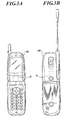
- FIGS. 3A and 3B show a portable telephone 100 functioning as a portable terminal which is equipped with the image pickup unit 50
- FIG. 4 is a control block diagram of the portable telephone 100.
- the image pickup unit 50 is, for example, arranged in the portable telephone 100 having a liquid crystal display on a front side so as to place the object side end plane of the casing 53 of the image pickup optical system 10 on a back side of the portable telephone 100. Also, the image pickup unit 50 is arranged under the liquid crystal display.
- the external connection terminal 54 of the image pickup unit 50 is connected to a control unit 101 of the portable telephone 100 and outputs an image signal such as a luminance signal and a color difference signal to the control unit 101.
- the portable telephone 100 comprises the control unit (CPU) 101 for executing a program corresponding to each type of processing, an input unit 60 for receiving a number instructed by using a key, a display unit 70 for displaying prescribed data and a formed image, a wireless communication unit 80 for performing various types of information communication with an external server, a storing unit (ROM) 91 for storing a system program of the portable telephone 100, various types of processing programs and necessary data such as a terminal ID, and a temporarily storing unit (RAM) 92, used as a work area, for temporarily storing the various types of processing programs and data executed or used by the control unit 101, data processed by the control unit 101 and image data obtained in the image pickup unit 50.
- the control unit (CPU) 101 for executing a program corresponding to each type of processing
- an input unit 60 for receiving a number instructed by using a key
- a display unit 70 for displaying prescribed data and a formed image
- a wireless communication unit 80 for performing various types of information communication with an external server
- ROM
- An image signal received from the image pickup unit 50 is stored in the storing unit 92, displayed on the display unit 70 and/or transmitted as image information to the outside through the wireless communication unit 80 under control of the control unit 101.
- the shape of an aspherical surface is expressed in a rectangular coordinate system, which has a vertex of the surface set as an origin and an optical axial direction set as an X axis, according to a following formula by using R denoting a curvature radius of the aspherical surface at the vertex, K denoting a conic constant, and A4, A6, A8, A10 and A12 denoting coefficients of the aspherical surface.
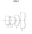
- FIG. 5 is a representative sectional view of a small-sized image pickup lens according to Examples 1 and 2 of the present invention.
- Lens data is shown in Tables 1, 2 and 3.
- FIGS. 6A to 6E are views of various types aberration according to Example 1, FIG. 6A shows spherical aberration, FIG. 6B shows astigmatism, FIG. 6C shows distortion, and FIGS. 6D and 6E show meridional coma.
- the first lens L1 is formed out of the glass material.
- the second lens L2 and the fourth lens L4 are plastic lenses of polyolefin, and saturated water absorption rates of the lenses L2 and L4 are respectively not more than 0.01 %.
- the third lens L3 is a plastic lens of polycarbonate, and a saturated water absorption rate of the lens L3 is 0.4 %.
- Lens data is shown in Tables 5, 6 and 7.
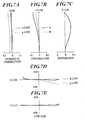
- FIGS. 7A to 7E are views of various types aberration according to Example 2, FIG. 7A shows spherical aberration, FIG. 7B shows astigmatism, FIG. 7C shows distortion, and FIGS. 7D and 7E show meridional coma.
- the first lens L1 is formed out of the glass material.
- the second lens L2 and the fourth lens L4 are plastic lenses of polyolefin, and saturated water absorption rates of the lenses L2 and L4 are respectively not more than 0.01 %.
- the third lens L3 is a plastic lens of polycarbonate, and a saturated water absorption rate of the lens L3 is 0.4 %.
- FIG. 8 is a representative sectional view of a small-sized image pickup lens according to Example 3 of the present invention.
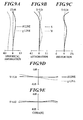
- FIGS. 9A to 9E are views of various types aberration according to Example 3, FIG. 9A shows spherical aberration, FIG. 9B shows astigmatism, FIG. 9C shows distortion, and FIGS. 9D and 9E show meridional coma.
- Example 3 the aperture stop S is arranged on the side nearest to the object side, and a plane parallel plate corresponding to an infrared ray cut filter is arranged nearest to the image side.
- the first lens L1 is formed out of the glass material.
- the second lens L2 and the fourth lens L4 are plastic lenses of polyolefin, and saturated water absorption rates of the lenses L2 and L4 are respectively not more than 0.01 %.
- the third lens L3 is a plastic lens of polycarbonate, and a saturated water absorption rate of the lens L3 is 0.4 %.
- Lens data is shown in Tables 13, 14 and 15.
- FIG. 10 is a representative sectional view of a small-sized image pickup lens according to Example 4 of the present invention
- FIGS. 11A to 11E are views of various types aberration according to Example 4,
- FIG. 11A shows spherical aberration
- FIG. 11B shows astigmatism
- FIG. 11C shows distortion
- FIGS. 11D and 11E show meridional coma.
- Example 3 the aperture stop S is arranged nearest to the object side, and a plane parallel plate corresponding to an infrared ray cut filter is arranged.
- the first lens L1 is formed out of the glass material.
- the second lens L2 and the fourth lens L4 are plastic lenses of polyolefin, and saturated water absorption rates of the lenses L2 and L4 are respectively not more than 0.01 %.
- the third lens L3 is a plastic lens of polycarbonate, and a saturated water absorption rate of the lens L3 is 0.4 %.
- the degree ( ⁇ fB) of change of the back focal length caused by the increase of the temperature is calculated while disregarding the influence of thermal expansion of the plastic lens caused by the increase of the temperature.
- the reason is that the positional change of the image point caused by the increase of the temperature is mainly caused by the change of the refractive index of the plastic lens.
- the design for the maintenance of a telecentric characteristic of a light flux on the image side is not sufficiently performed.
- the telecentric characteristic denotes that a principal ray of a light flux corresponding to each image point becomes parallel to the optical axis after the principal ray goes out from the final surface of the lenses.
- the telecentric characteristic denotes that the position of an exit pupil of the optical system is sufficiently set away from an image surface.
- each of Examples 1 to 4 denotes a design example of an optical system further miniaturized according to the reduction of the requirement degree of the telecentric characteristic.
- the plurality of positive lenses and the negative lens having the comparatively strong refractive power are arranged in that order from the object side, so that the total lens length can be easily shortened. Also, when the convex surface of the first lens faces toward the object side, the total lens length can be shortened.
- two positive lenses of the first lens and the second lens respectively having the positive refractive power are arranged nearest to the object side. Therefore, the positive refractive power can be distributed to the first and second lenses, and the generation of both the spherical aberration and the coma can be suppressed.
- the concave surface of the third lens faces toward the object side, and the third lens is set to be a negative lens (that is, a lens having the negative refractive power) having the meniscus shape. Therefore, the spherical aberration, the coma and the astigmatism can be preferably corrected.
- the convex surface of the fourth lens faces toward the object side, and the fourth lens is formed in the meniscus shape. Therefore, the telecentric characteristic of the light flux on the image side can be easily maintained in the periphery of the image screen.
- the whole image pickup device can be miniaturized and lightened in weight.
- f12/f when f12/f is set to be higher than the lower limit by satisfying the conditional formula (2) or (5), the combined positive refractive power of the first lens and the second lens is appropriately suppressed. Therefore, the generation of both the higher order spherical aberration and the coma can be suppressed to a low degree. Further, f12/f is set to be lower than the higher limit. Therefore, the combined positive refractive power of the first lens and the second lens is appropriately obtained, and the total lens length can be shortened.
- conditional formulas (1) to (3) and (4) to (6) indicate conditions for obtaining a small-sized image pickup lens in which the aberration is preferably corrected.
- conditional formulas (1) and (4) indicate conditions for achieving the shortening of the total lens length.
- L/2Y or L'/2Y is lower than the upper limit of the conditional formula (1) or (4), the total lens length is directed to be shortened.
- the symbol L of the conditional formula (1) indicates a distance on the optical axis from the object side surface of the first lens to the image side focal point of the whole image pickup lens.
- the symbol L' of the conditional formula (4) indicates a distance on the optical axis from the aperture stop to the image side focal point of the whole image pickup lens.
- image side focal point denotes an image point obtained when a parallel ray parallel to the optical axis is incident on the image pickup lens.
- R5/((N3 - 1) ⁇ f) is set to be lower than the upper limit by satisfying the conditional formula (7) or (9), the excess of the negative refractive power of the object side surface of the third lens can be avoided. Therefore, the generation of the excessive spherical aberration and the generation of coma flare of an abaxial light flux can be suppressed, and a preferable image quality can be obtained. Further, when R5/((N3 - 1) ⁇ f) is set to be higher than the lower limit of the conditional formula (7) or (9), the negative refractive power of the object side surface of the third lens can be maintained, and a positive Petzval's sum is lowered. Therefore, the curvature of image surface, the axial chromatic aberration and the lateral chromatic aberration can be preferably corrected.
- the positive refractive power of the air lens formed between the third lens and the fourth lens can be appropriately set according to the conditional formula (8). Therefore, the correction of the curvature of image surface and the distortion and the maintenance of the telecentric characteristic of the light flux on the image side can be performed in good balance.
- the image side surface of the fourth lens and placed nearest to the image side is formed in the aspheric shape satisfying the conditional formula (10), the telecentric characteristic particularly for the light flux at the high angle of view can be maintained.
- the positive first lens is formed out of the glass material of which the refractive index hardly changes with the temperature
- the second, third and fourth lenses are formed out of the plastic material.
- the second lens is the positive lens having the comparatively strong refractive power
- the third lens is the negative lens having the comparatively strong refractive power. Therefore, the influence of the second lens on the position of the image point changing with the temperature can cancel out that of the third lens, and the positional change of the image point in the whole image pickup lens caused by the temperature change can be suppressed to a low degree.
- the first lens is set as the glass lens, no plastic lens easily scratched is exposed to the outside. Therefore, the maintenance of the image pickup lens can be improved.
- the first lens and the second lens respectively have the positive refractive power, and the required refractive power is distributed to the first and second lenses. Therefore, it is not required to extremely lower the curvature radius in each lens. Accordingly, the forming work for the glass lens denoting the first lens can be easily performed, and the productivity of the first lens can be improved.
- the second, third and fourth lenses are formed out of the plastic material. Therefore, the shape of the flange portion of each lens placed out of an area of the lens effective diameter can be freely designed while integrally forming the flange portion and the lens. Assuming that the flange portions of the lenses are easily fitted onto each other, the structure of the lenses can be obtained so as to easily make the optical axes of the lenses agree with each other. Further, when the lens structure is set to make each flange determine the interval of the corresponding pair of lenses, no spacer is required. Therefore, the number of parts of the image pickup lens can be reduced, and the productivity of the image pickup lens can be improved.
- each lens can be easily formed in the aspheric shape, and the correction of aberration can be easily performed.
- the lenses are set so as to satisfy the conditional formula (13). Therefore, the combined focal length of the plastic lenses can be set to a large value to suppress a sum of values of the refractive power of the lenses to a low value, and the positional change of the image point caused by the temperature change can be suppressed to a low degree.
- the plastic material having the saturated water absorption rate not more than 0.7 % is used. Therefore, the non-uniformity of the refractive index of the lens caused by a rapid change of humidity can be suppressed, and the effects of the plastic lens can be obtained while maintaining a preferable image forming performance.
- the first positive lens having the convex surface which is placed nearest to the object side and faces toward the object side, is arranged. Therefore, the total lens length can be shortened as compared with a first negative lens.
- one positive lens having the positive refractive power is set to a glass lens, and another positive lens and one negative lens are set to plastic lenses. Therefore, the large positive refractive power can be distributed to the glass lens and the plastic lens. Further, the influence of the plastic lens having the positive refractive power on the positional change of the image point caused by the temperature change cancels out that of the plastic lens having the negative refractive power. Therefore, effects of the miniaturization, the lightening-in-weight and the mass productivity of the lens can be obtained due to the plastic lens.
- the image side surface of the fourth lens is formed in the aspheric shape. Therefore, the telecentric characteristic particularly for the light flux at the high angle of view can be maintained.
- three lenses selected from the first, second, third and fourth lenses are formed out of the plastic material. Therefore, effects of the miniaturization, the lightening-in-weight, the low cost based on the mass productivity and the easy formation of the aspherical surface can be obtained due to the lenses formed out of the plastic material.
- the first lens is formed out of the glass material. Therefore, the generation of flaws in the first lens of the position damaged most easily can be reduced, the first lens protects the other lenses formed out of the plastic material, and the maintenance of the first lens can be improved.
- the lenses are set so as to satisfy the conditional formula (17). Therefore, the combined focal length of the plastic lenses can be set to a large value to suppress a sum of values of the refractive power of the lenses to a low value, and the positional change of the image point caused by the temperature change can be suppressed to a low degree.
- the plastic material having the saturated water absorption rate not more than 0.7 % is used. Therefore, the non-uniformity of the refractive index of the lens caused by a rapid change of humidity can be suppressed, and the effects of the plastic lens can be obtained while maintaining a preferable image forming performance.
- the total lens length can be shortened according to the conditional formula (18), and the whole image pickup device can be miniaturized and lightened in weight.
- the total lens length can be appropriately shortened according to the conditional formula (19) while suppressing the generation of both the higher order spherical aberration and the coma to a low degree.
- the axial chromatic aberration and the lateral chromatic aberration can be corrected in good balance according to the conditional formula (20).
- the plurality of positive lenses and the negative lens respectively having the comparatively strong refractive power are arranged in that order from the object side, so that the total lens length can be easily shortened.
- the lens placed nearest to the object side has the positive refractive power to shorten the length in the optical axis
- the image pickup lens comprises four lenses.
- the number of lenses is four, the correction of various types aberration, the improvement of the telecentric characteristic and the distribution of the refractive power can be easily obtained, and the image pickup unit advantageous for the miniaturization, the high image quality and the lightening-in-weight can be provided.
- the image pickup lens having the above-described effects is mounted on the image pickup unit. Therefore, the image pickup unit having effects of the miniaturization, the lightening-in-weight and the high image quality can be provided.
- the image pickup unit described above is mounted on the portable terminal. Therefore, a miniaturized lightweight portable terminal capable to form an image at the high image quality can be provided.
Landscapes
- Physics & Mathematics (AREA)
- General Physics & Mathematics (AREA)
- Optics & Photonics (AREA)
- Lenses (AREA)
- Cameras In General (AREA)
Claims (6)
- Unité d'objectif de prise de vues (50) comprenant :un élément de prise de vues à semi-conducteurs (51) ayant une unité de transfert photoélectrique (51a);un objectif de prise de vues pour former une image d'un objet dans l'unité de transfert photoélectrique (51a) de l'élément de prise de vues à semi-conducteurs (51) constitué de :quatre lentilles disposées dans l'ordre d'une première lentille (L1), d'une deuxième lentille (L2), d'une troisième lentille (L3) et d'une quatrième lentille (L4) depuis un côté objet, et chacune de la première, la deuxième, la troisième et la quatrième lentille (L1, L2, L3, L4) est une lentille unique ;un diaphragme d'ouverture (s), un substrat (52) pour supporter l'élément de prise de vues à semi-conducteurs (51), le substrat (52) comprenant une borne de connexion externe (54) à travers laquelle un signal électrique est transmis ou reçu ;un boîtier (53) constitué d'une substance opaque à la lumière et comprenant une ouverture pour la lumière incidente entrant d'un côté objet, etdans laquelle la première lentille (L1) a une réfringence positive et a une surface convexe faisant face au côté objet et est constituée d'un matériau en verre, une lentille ou deux lentilles sélectionnées parmi la deuxième, la troisième et la quatrième lentille (L2, L3, L4) ont une réfringence positive et une lentille sélectionnée parmi la deuxième, la troisième et la quatrième lentille (L2, L3, L4) a une réfringence négative, et les lentilles autres que la première lentille (L1) sont constituées d'une matière plastique, etla quatrième lentille (L4) est une lentille ménisque avec une surface convexe faisant face à l'objet et une surface côté image de la quatrième lentille (L4) satisfait l'équation conditionnelle suivante (14) :
 pour une valeur de déplacement X d'une surface asphérique exprimée par la formule (15) :
 et une valeur de déplacement X0 d'une composante de surface quadratique en rotation de la surface asphérique exprimée par la formule (16) :
 dans une plage de h satisfaisant la relation : 0,5 hmax < h < hmax,dans laquelle un vertex de la surface côté image de la quatrième lentille (L4) est défini comme origine, une direction d'un axe optique est défini comme étant l'axe X, h désigne une hauteur dans une direction arbitraire perpendiculaire à l'axe optique, Ai désigne un coefficient de ième ordre de la surface asphérique pour la surface côté image de la quatrième lentille (L4), hmax désigne un rayon effectif maximum, R8 désigne un rayon de courbure de la surface côté image de la quatrième lentille (L4), et K8 désigne une constante conique pour la surface côté image de la quatrième lentille (L4), au moins une valeur de K8 ou Ai étant différente de zéro,et dans laquelle une équation conditionnelle suivante (17) est satisfaite :
 f234 désignant une longueur focale combinée de la deuxième, la troisième et la quatrième lentilles (L2, L3, L4), et f désignant une longueur focale de l'ensemble de l'objectif de prise de vues.
 - Unité d'objectif de prise de vues (50) selon la revendication 1, dans laquelle une longueur de l'unité de prise de vues (50) dans une direction d'un axe optique de l'objectif de prise de vues n'excède pas 15 mm.
- Unité d'objectif de prise de vues (50) selon la revendication 1 ou la revendication 2, dans laquelle un taux d'absorption d'eau saturée de la matière plastique n'excède pas 0,7 %.
- Unité d'objectif de prise de vues (50) selon les revendications 1, 2 ou 3 dans laquelle les équations conditionnelles suivantes (18), (19) et (20) sont satisfaites :


dans lesquelles L désigne une distance sur un axe optique depuis la surface de la première lentille (L1) jusqu'à un point focal côté image de l'ensemble de l'objectif de prise de vues, 2Y désigne la longueur d'une ligne diagonale sur un écran image effectif, f12 désigne une longueur focale combinée de la première lentille (L1) et de la deuxième lentille (L2), f désigne une longueur focale de l'ensemble de l'objectif de prise de vues, vP désigne un nombre d'Abbe de la lentille ayant la réfringence positive la plus forte, vN désigne un nombre d'Abbe de la lentille ayant la réfringence négative la plus forte. - Unité d'objectif de prise de vues (50) selon les revendications 1, 2, 3 ou 4 dans laquelle la deuxième lentille (L2) a la réfringence positive et la troisième lentille (L3) a la réfringence négative.
- Terminal portable comprenant l'unité d'objectif de prise de vues (50) selon les revendications 1, 2, 3, 4 ou 5.
Priority Applications (1)
| Application Number | Priority Date | Filing Date | Title |
|---|---|---|---|
| EP06019015A EP1757967A3 (fr) | 2002-07-18 | 2003-07-07 | Objectif de prise de vue à quatre lentilles, unité de prise de vue et terminal portable |
Applications Claiming Priority (2)
| Application Number | Priority Date | Filing Date | Title |
|---|---|---|---|
| JP2002209625 | 2002-07-18 | ||
| JP2002209625 | 2002-07-18 |
Related Child Applications (1)
| Application Number | Title | Priority Date | Filing Date |
|---|---|---|---|
| EP06019015A Division EP1757967A3 (fr) | 2002-07-18 | 2003-07-07 | Objectif de prise de vue à quatre lentilles, unité de prise de vue et terminal portable |
Publications (3)
| Publication Number | Publication Date |
|---|---|
| EP1382985A2 EP1382985A2 (fr) | 2004-01-21 |
| EP1382985A3 EP1382985A3 (fr) | 2005-05-04 |
| EP1382985B1 true EP1382985B1 (fr) | 2008-11-19 |
Family
ID=29774650
Family Applications (2)
| Application Number | Title | Priority Date | Filing Date |
|---|---|---|---|
| EP06019015A Withdrawn EP1757967A3 (fr) | 2002-07-18 | 2003-07-07 | Objectif de prise de vue à quatre lentilles, unité de prise de vue et terminal portable |
| EP03254302A Expired - Lifetime EP1382985B1 (fr) | 2002-07-18 | 2003-07-07 | Unité d'objectif de prise de vue et terminal portable |
Family Applications Before (1)
| Application Number | Title | Priority Date | Filing Date |
|---|---|---|---|
| EP06019015A Withdrawn EP1757967A3 (fr) | 2002-07-18 | 2003-07-07 | Objectif de prise de vue à quatre lentilles, unité de prise de vue et terminal portable |
Country Status (8)
| Country | Link |
|---|---|
| US (1) | US6813099B2 (fr) |
| EP (2) | EP1757967A3 (fr) |
| JP (1) | JP4706787B2 (fr) |
| KR (1) | KR100954635B1 (fr) |
| CN (2) | CN1933551B (fr) |
| AT (1) | ATE414926T1 (fr) |
| DE (1) | DE60324739D1 (fr) |
| TW (1) | TWI261120B (fr) |
Cited By (1)
| Publication number | Priority date | Publication date | Assignee | Title |
|---|---|---|---|---|
| TWI625563B (zh) * | 2017-03-23 | 2018-06-01 | 大立光電股份有限公司 | 塑膠鏡筒、相機模組及電子裝置 |
Families Citing this family (62)
| Publication number | Priority date | Publication date | Assignee | Title |
|---|---|---|---|---|
| DE10109787A1 (de) * | 2001-02-28 | 2002-10-02 | Infineon Technologies Ag | Digitale Kamera mit einem lichtempfindlichen Sensor |
| ATE315794T1 (de) * | 2002-03-25 | 2006-02-15 | Konishiroku Photo Ind | Dreilinsiges objektiv |
| JP4400193B2 (ja) * | 2003-12-02 | 2010-01-20 | コニカミノルタオプト株式会社 | 撮像レンズ |
| CN100376915C (zh) * | 2004-03-27 | 2008-03-26 | 鸿富锦精密工业(深圳)有限公司 | 数码相机镜头 |
| US7369332B2 (en) * | 2004-04-13 | 2008-05-06 | Carl Zeiss Smt Gmbh | Closing module for an optical arrangement |
| CN1323306C (zh) * | 2004-06-16 | 2007-06-27 | 清华大学 | 微型摄像镜头系统 |
| US6898030B1 (en) * | 2004-06-17 | 2005-05-24 | Prodisc Technology Inc. | Camera lens assembly |
| JP2006047858A (ja) * | 2004-08-06 | 2006-02-16 | Nidec Copal Corp | 撮像レンズ |
| CN100462769C (zh) * | 2004-08-18 | 2009-02-18 | 清华大学 | 微型摄像镜头系统 |
| CN100462771C (zh) * | 2004-09-08 | 2009-02-18 | 清华大学 | 微型摄像镜头系统 |
| WO2006037651A1 (fr) | 2004-10-08 | 2006-04-13 | Carl Zeiss Smt Ag | Systeme de projection optique |
| DE102004049871B4 (de) * | 2004-10-13 | 2017-05-24 | Robert Bosch Gmbh | Verfahren zur Herstellung einer Objektivaufnahme für ein Objektiv einer Kamera und Kamera für Kraftfahrzeuganwendungen |
| US7227236B1 (en) | 2005-04-26 | 2007-06-05 | Amkor Technology, Inc. | Image sensor package and its manufacturing method |
| US20070272827A1 (en) * | 2005-04-27 | 2007-11-29 | Amkor Technology, Inc. | Image sensor package having mount holder attached to image sensor die |
| CN100468182C (zh) * | 2005-05-06 | 2009-03-11 | 鸿富锦精密工业(深圳)有限公司 | 复合透镜系统 |
| US7576401B1 (en) | 2005-07-07 | 2009-08-18 | Amkor Technology, Inc. | Direct glass attached on die optical module |
| KR100703469B1 (ko) * | 2005-07-07 | 2007-04-03 | 삼성전자주식회사 | 촬상용 광학계 |
| WO2007096992A1 (fr) * | 2006-02-24 | 2007-08-30 | Matsushita Electric Industrial Co., Ltd. | Dispositif de traitement d'image et dispositif terminal portable |
| JP4922626B2 (ja) * | 2006-02-27 | 2012-04-25 | 株式会社タムロン | 撮像レンズ |
| KR20070104010A (ko) * | 2006-04-21 | 2007-10-25 | 엘지이노텍 주식회사 | 카메라 모듈 및 이를 구비하는 휴대용 단말기 |
| JP4947700B2 (ja) * | 2006-09-21 | 2012-06-06 | 富士フイルム株式会社 | 広角撮像レンズ、撮像装置、およびカメラモジュール |
| JP5000247B2 (ja) | 2006-09-25 | 2012-08-15 | 富士フイルム株式会社 | 撮像レンズ |
| US7663815B2 (en) * | 2007-05-22 | 2010-02-16 | Enplas Corporation | Imaging lens |
| KR100906842B1 (ko) * | 2007-06-22 | 2009-07-08 | 엘지이노텍 주식회사 | 광학계 |
| JP2009069369A (ja) * | 2007-09-12 | 2009-04-02 | Fujinon Corp | 撮像レンズおよび撮像装置 |
| EP2037306A1 (fr) | 2007-09-12 | 2009-03-18 | Fujinon Corporation | Lentille d'imagerie et appareil d'imagerie |
| JP5043710B2 (ja) | 2008-02-14 | 2012-10-10 | 富士フイルム株式会社 | 撮像レンズおよび撮像装置 |
| CN101526655A (zh) * | 2008-03-04 | 2009-09-09 | 鸿富锦精密工业(深圳)有限公司 | 镜片及镜头模组 |
| JP2009282223A (ja) * | 2008-05-21 | 2009-12-03 | Konica Minolta Opto Inc | 撮像レンズ、撮像ユニット及び携帯端末 |
| CN101592767A (zh) * | 2008-05-26 | 2009-12-02 | 鸿富锦精密工业(深圳)有限公司 | 镜片组 |
| TWI420179B (zh) * | 2008-06-13 | 2013-12-21 | Hon Hai Prec Ind Co Ltd | 鏡片組 |
| US7710667B2 (en) * | 2008-06-25 | 2010-05-04 | Aptina Imaging Corp. | Imaging module with symmetrical lens system and method of manufacture |
| JP5097059B2 (ja) * | 2008-09-03 | 2012-12-12 | パナソニック株式会社 | 撮像レンズ及びそれを用いた撮像装置 |
| US7796349B2 (en) * | 2008-10-09 | 2010-09-14 | Visera Technologies Company Limited | Miniature image capture lens |
| JP5668276B2 (ja) * | 2009-05-15 | 2015-02-12 | ソニー株式会社 | 固体撮像装置、および電子機器 |
| CN102033293B (zh) * | 2009-09-25 | 2013-07-03 | 鸿富锦精密工业(深圳)有限公司 | 取像镜头 |
| US8279535B2 (en) * | 2009-10-02 | 2012-10-02 | Omnivision Technologies, Inc. | Image capture lens modules and image capture systems |
| CN102073126B (zh) * | 2009-11-25 | 2012-07-25 | 大立光电股份有限公司 | 取像光学镜头 |
| JP2013068857A (ja) * | 2011-09-26 | 2013-04-18 | Sony Corp | 光学素子、撮像レンズ群および撮像装置 |
| TWI461732B (zh) * | 2012-11-09 | 2014-11-21 | Largan Precision Co Ltd | 影像擷取系統鏡頭組 |
| US9223113B2 (en) * | 2013-10-09 | 2015-12-29 | Genius Electronic Optical Co., Ltd. | Optical lens and electronic apparatus including the lens |
| TWI513998B (zh) * | 2013-10-31 | 2015-12-21 | Ability Opto Electronics Technologyco Ltd | Thin wide-angle four-piece imaging lens group |
| TWI472825B (zh) | 2013-11-13 | 2015-02-11 | Largan Precision Co Ltd | 取像透鏡組、取像裝置及可攜裝置 |
| JP2015102849A (ja) | 2013-11-28 | 2015-06-04 | カンタツ株式会社 | 撮像レンズ |
| TWI518357B (zh) * | 2014-02-26 | 2016-01-21 | 信泰光學(深圳)有限公司 | 成像鏡頭 |
| KR101626579B1 (ko) * | 2014-02-28 | 2016-06-01 | 대원전광주식회사 | 카메라 렌즈 모듈 |
| US10302918B2 (en) | 2015-02-06 | 2019-05-28 | Sony Corporation | Imaging lens and imaging unit |
| US10116853B2 (en) | 2015-11-11 | 2018-10-30 | Gopro, Inc. | Integrated sensor and lens assembly with differential threads adjustment |
| KR101813334B1 (ko) | 2015-11-24 | 2017-12-28 | 삼성전기주식회사 | 촬상 광학계 |
| US10070028B2 (en) * | 2016-02-10 | 2018-09-04 | Microsoft Technology Licensing, Llc | Optical systems and methods of use |
| TWI633331B (zh) * | 2016-05-09 | 2018-08-21 | 大立光電股份有限公司 | 成像鏡頭及電子裝置 |
| CN107144943B (zh) * | 2017-07-18 | 2022-09-09 | 浙江舜宇光学有限公司 | 摄像镜头 |
| TWI634360B (zh) * | 2017-09-29 | 2018-09-01 | 大立光電股份有限公司 | 電子裝置 |
| CN115113374B (zh) * | 2017-12-08 | 2024-09-13 | 大立光电股份有限公司 | 电子装置 |
| CN110568575B (zh) * | 2018-06-06 | 2021-06-01 | 华为技术有限公司 | 透镜模组、拍摄模组及终端设备 |
| CN109814235B (zh) * | 2018-12-28 | 2022-02-08 | 玉晶光电(厦门)有限公司 | 光学成像镜头 |
| CN110174751B (zh) * | 2019-06-06 | 2021-06-18 | 歌尔光学科技有限公司 | 投影镜头及投影显示设备 |
| CN114355563A (zh) * | 2019-06-27 | 2022-04-15 | 华为技术有限公司 | 光学镜头组、摄像头及终端设备 |
| CN112666679B (zh) * | 2019-10-16 | 2022-03-18 | 比亚迪股份有限公司 | 移动通信设备的摄像头模组和具有其的移动通信设备 |
| TWI714518B (zh) * | 2020-08-12 | 2020-12-21 | 大立光電股份有限公司 | 成像鏡頭、取像裝置及電子裝置 |
| TWI777542B (zh) * | 2020-12-23 | 2022-09-11 | 大立光電股份有限公司 | 成像鏡頭與電子裝置 |
| CN121050064B (zh) * | 2025-11-05 | 2026-03-27 | 宁波舜宇车载光学技术有限公司 | 光学镜头及电子设备 |
Citations (1)
| Publication number | Priority date | Publication date | Assignee | Title |
|---|---|---|---|---|
| JP2000180719A (ja) * | 1998-12-11 | 2000-06-30 | Minolta Co Ltd | 撮影レンズ系 |
Family Cites Families (16)
| Publication number | Priority date | Publication date | Assignee | Title |
|---|---|---|---|---|
| DE1184982B (de) * | 1961-05-05 | 1965-01-07 | Voigtlaender Ag | Objektiv aus vier freistehenden Einzellinsen |
| JPS5271253A (en) * | 1975-12-11 | 1977-06-14 | Canon Inc | Compound lens of high resolving power |
| JPS58215617A (ja) * | 1982-06-09 | 1983-12-15 | Olympus Optical Co Ltd | 望遠写真レンズ |
| JPS616616A (ja) * | 1984-06-20 | 1986-01-13 | Konishiroku Photo Ind Co Ltd | 広角レンズ |
| JP2679017B2 (ja) * | 1986-12-27 | 1997-11-19 | ミノルタ株式会社 | 2焦点切替レンズ系 |
| JP3242099B2 (ja) * | 1988-06-01 | 2001-12-25 | 株式会社日立製作所 | ビデオ・カメラ・ユニット |
| JPH07281089A (ja) * | 1994-04-12 | 1995-10-27 | Olympus Optical Co Ltd | 撮影レンズ |
| JPH09222560A (ja) * | 1996-02-19 | 1997-08-26 | Olympus Optical Co Ltd | 結像レンズ |
| JP3610160B2 (ja) * | 1996-03-22 | 2005-01-12 | オリンパス株式会社 | 写真レンズ |
| JP4233062B2 (ja) * | 1997-03-26 | 2009-03-04 | フジノン株式会社 | 結像レンズ |
| US7007126B2 (en) * | 1998-02-13 | 2006-02-28 | Intel Corporation | Accessing a primary bus messaging unit from a secondary bus through a PCI bridge |
| JPH11249013A (ja) * | 1998-02-27 | 1999-09-17 | Fuji Photo Optical Co Ltd | 結像レンズおよびこれを用いた光学装置 |
| US6441971B2 (en) * | 1999-09-27 | 2002-08-27 | Alex Ning | Compact lens with external aperture stop |
| JP3424030B2 (ja) * | 2001-01-31 | 2003-07-07 | カシオ計算機株式会社 | 撮影レンズ |
| JP4032667B2 (ja) * | 2001-06-05 | 2008-01-16 | カシオ計算機株式会社 | 撮影レンズ |
| JP3695449B2 (ja) * | 2003-01-30 | 2005-09-14 | コニカミノルタオプト株式会社 | 撮像レンズ |
-
2003
- 2003-06-30 TW TW092117843A patent/TWI261120B/zh not_active IP Right Cessation
- 2003-07-07 EP EP06019015A patent/EP1757967A3/fr not_active Withdrawn
- 2003-07-07 EP EP03254302A patent/EP1382985B1/fr not_active Expired - Lifetime
- 2003-07-07 US US10/614,596 patent/US6813099B2/en not_active Expired - Fee Related
- 2003-07-07 AT AT03254302T patent/ATE414926T1/de not_active IP Right Cessation
- 2003-07-07 DE DE60324739T patent/DE60324739D1/de not_active Expired - Lifetime
- 2003-07-15 KR KR1020030048182A patent/KR100954635B1/ko not_active Expired - Fee Related
- 2003-07-18 CN CN2006101100924A patent/CN1933551B/zh not_active Expired - Fee Related
- 2003-07-18 CN CNA03143875XA patent/CN1475828A/zh active Pending
-
2009
- 2009-10-05 JP JP2009231262A patent/JP4706787B2/ja not_active Expired - Lifetime
Patent Citations (1)
| Publication number | Priority date | Publication date | Assignee | Title |
|---|---|---|---|---|
| JP2000180719A (ja) * | 1998-12-11 | 2000-06-30 | Minolta Co Ltd | 撮影レンズ系 |
Cited By (1)
| Publication number | Priority date | Publication date | Assignee | Title |
|---|---|---|---|---|
| TWI625563B (zh) * | 2017-03-23 | 2018-06-01 | 大立光電股份有限公司 | 塑膠鏡筒、相機模組及電子裝置 |
Also Published As
| Publication number | Publication date |
|---|---|
| KR20040010184A (ko) | 2004-01-31 |
| DE60324739D1 (de) | 2009-01-02 |
| EP1382985A3 (fr) | 2005-05-04 |
| US6813099B2 (en) | 2004-11-02 |
| TWI261120B (en) | 2006-09-01 |
| EP1382985A2 (fr) | 2004-01-21 |
| ATE414926T1 (de) | 2008-12-15 |
| US20040012861A1 (en) | 2004-01-22 |
| CN1933551A (zh) | 2007-03-21 |
| KR100954635B1 (ko) | 2010-04-27 |
| CN1933551B (zh) | 2010-05-12 |
| TW200404166A (en) | 2004-03-16 |
| JP4706787B2 (ja) | 2011-06-22 |
| EP1757967A2 (fr) | 2007-02-28 |
| CN1475828A (zh) | 2004-02-18 |
| EP1757967A3 (fr) | 2007-03-14 |
| JP2010002930A (ja) | 2010-01-07 |
Similar Documents
| Publication | Publication Date | Title |
|---|---|---|
| EP1382985B1 (fr) | Unité d'objectif de prise de vue et terminal portable | |
| EP1348990B1 (fr) | Objectif composé de trois lentilles | |
| EP1416306B1 (fr) | Objectif de prise de vue, dispositif de prise de vue et téléphone mobile muni du dit objectif ou dispositif | |
| EP1357414B1 (fr) | Objectif miniature de capture d'images et appareil mobile équipé avec un tel objectif | |
| US7609313B2 (en) | Image pick-up lens, image pick-up unit and mobile terminal | |
| JP4453276B2 (ja) | 撮像レンズ,撮像ユニット及びこれを備える携帯端末 | |
| JP4506083B2 (ja) | 撮像レンズ,これを備える撮像装置、撮像ユニット及び撮像ユニットを備える携帯端末 | |
| EP1703309B1 (fr) | Objectif de capture d'images, appareil de capture d'images et terminal mobile doté d'un appareil de capture d'images | |
| JP4940704B2 (ja) | 撮像レンズ、撮像装置及び該撮像装置を備えた携帯端末 | |
| US7602560B2 (en) | Image pickup lens, image pickup apparatus and mobile terminal | |
| JP4760109B2 (ja) | 撮像レンズ、撮像装置及び携帯端末 | |
| JP2009282223A (ja) | 撮像レンズ、撮像ユニット及び携帯端末 | |
| JP4894222B2 (ja) | 撮像レンズ、撮像ユニット及び携帯端末 | |
| JP2004004742A (ja) | 小型の撮像レンズ、撮像ユニット及び携帯端末 | |
| EP1653267B1 (fr) | Objectif compact ayant trois lentilles simples | |
| JP2003215446A (ja) | 小型撮像レンズ | |
| JP4617744B2 (ja) | 撮像レンズ、撮像ユニット及びこの撮像ユニットを備える携帯端末 |
Legal Events
| Date | Code | Title | Description |
|---|---|---|---|
| PUAI | Public reference made under article 153(3) epc to a published international application that has entered the european phase |
Free format text: ORIGINAL CODE: 0009012 |
|
| AK | Designated contracting states |
Kind code of ref document: A2 Designated state(s): AT BE BG CH CY CZ DE DK EE ES FI FR GB GR HU IE IT LI LU MC NL PT RO SE SI SK TR |
|
| AX | Request for extension of the european patent |
Extension state: AL LT LV MK |
|
| RIC1 | Information provided on ipc code assigned before grant |
Ipc: 7G 02B 13/16 B Ipc: 7G 02B 13/02 B Ipc: 7G 02B 9/34 A |
|
| 17P | Request for examination filed |
Effective date: 20050103 |
|
| PUAL | Search report despatched |
Free format text: ORIGINAL CODE: 0009013 |
|
| RIC1 | Information provided on ipc code assigned before grant |
Ipc: 7G 02B 13/18 B Ipc: 7G 02B 13/16 B Ipc: 7G 02B 13/02 B Ipc: 7G 02B 9/34 A |
|
| AK | Designated contracting states |
Kind code of ref document: A3 Designated state(s): AT BE BG CH CY CZ DE DK EE ES FI FR GB GR HU IE IT LI LU MC NL PT RO SE SI SK TR |
|
| AX | Request for extension of the european patent |
Extension state: AL LT LV MK |
|
| RAP1 | Party data changed (applicant data changed or rights of an application transferred) |
Owner name: KONICA MINOLTA OPTO, INC. |
|
| AKX | Designation fees paid |
Designated state(s): AT BE BG CH CY CZ DE DK EE ES FI FR GB GR HU IE IT LI LU MC NL PT RO SE SI SK TR |
|
| AXX | Extension fees paid |
Extension state: MK Payment date: 20050103 Extension state: LT Payment date: 20050103 Extension state: LV Payment date: 20050103 Extension state: AL Payment date: 20050103 |
|
| 17Q | First examination report despatched |
Effective date: 20060321 |
|
| RTI1 | Title (correction) |
Free format text: IMAGE PICKUP LENS UNIT AND PORTABLE TERMINAL |
|
| GRAP | Despatch of communication of intention to grant a patent |
Free format text: ORIGINAL CODE: EPIDOSNIGR1 |
|
| GRAS | Grant fee paid |
Free format text: ORIGINAL CODE: EPIDOSNIGR3 |
|
| GRAA | (expected) grant |
Free format text: ORIGINAL CODE: 0009210 |
|
| AK | Designated contracting states |
Kind code of ref document: B1 Designated state(s): AT BE BG CH CY CZ DE DK EE ES FI FR GB GR HU IE IT LI LU MC NL PT RO SE SI SK TR |
|
| AX | Request for extension of the european patent |
Extension state: AL LT LV MK |
|
| REG | Reference to a national code |
Ref country code: GB Ref legal event code: FG4D |
|
| REG | Reference to a national code |
Ref country code: CH Ref legal event code: EP |
|
| REG | Reference to a national code |
Ref country code: IE Ref legal event code: FG4D |
|
| REF | Corresponds to: |
Ref document number: 60324739 Country of ref document: DE Date of ref document: 20090102 Kind code of ref document: P |
|
| PG25 | Lapsed in a contracting state [announced via postgrant information from national office to epo] |
Ref country code: ES Free format text: LAPSE BECAUSE OF FAILURE TO SUBMIT A TRANSLATION OF THE DESCRIPTION OR TO PAY THE FEE WITHIN THE PRESCRIBED TIME-LIMIT Effective date: 20090301 Ref country code: AT Free format text: LAPSE BECAUSE OF FAILURE TO SUBMIT A TRANSLATION OF THE DESCRIPTION OR TO PAY THE FEE WITHIN THE PRESCRIBED TIME-LIMIT Effective date: 20081119 |
|
| NLV1 | Nl: lapsed or annulled due to failure to fulfill the requirements of art. 29p and 29m of the patents act | ||
| PG25 | Lapsed in a contracting state [announced via postgrant information from national office to epo] |
Ref country code: NL Free format text: LAPSE BECAUSE OF FAILURE TO SUBMIT A TRANSLATION OF THE DESCRIPTION OR TO PAY THE FEE WITHIN THE PRESCRIBED TIME-LIMIT Effective date: 20081119 Ref country code: SI Free format text: LAPSE BECAUSE OF FAILURE TO SUBMIT A TRANSLATION OF THE DESCRIPTION OR TO PAY THE FEE WITHIN THE PRESCRIBED TIME-LIMIT Effective date: 20081119 |
|
| PG25 | Lapsed in a contracting state [announced via postgrant information from national office to epo] |
Ref country code: EE Free format text: LAPSE BECAUSE OF FAILURE TO SUBMIT A TRANSLATION OF THE DESCRIPTION OR TO PAY THE FEE WITHIN THE PRESCRIBED TIME-LIMIT Effective date: 20081119 Ref country code: RO Free format text: LAPSE BECAUSE OF FAILURE TO SUBMIT A TRANSLATION OF THE DESCRIPTION OR TO PAY THE FEE WITHIN THE PRESCRIBED TIME-LIMIT Effective date: 20081119 Ref country code: BG Free format text: LAPSE BECAUSE OF FAILURE TO SUBMIT A TRANSLATION OF THE DESCRIPTION OR TO PAY THE FEE WITHIN THE PRESCRIBED TIME-LIMIT Effective date: 20090219 Ref country code: DK Free format text: LAPSE BECAUSE OF FAILURE TO SUBMIT A TRANSLATION OF THE DESCRIPTION OR TO PAY THE FEE WITHIN THE PRESCRIBED TIME-LIMIT Effective date: 20081119 Ref country code: BE Free format text: LAPSE BECAUSE OF FAILURE TO SUBMIT A TRANSLATION OF THE DESCRIPTION OR TO PAY THE FEE WITHIN THE PRESCRIBED TIME-LIMIT Effective date: 20081119 |
|
| PG25 | Lapsed in a contracting state [announced via postgrant information from national office to epo] |
Ref country code: SE Free format text: LAPSE BECAUSE OF FAILURE TO SUBMIT A TRANSLATION OF THE DESCRIPTION OR TO PAY THE FEE WITHIN THE PRESCRIBED TIME-LIMIT Effective date: 20090219 Ref country code: PT Free format text: LAPSE BECAUSE OF FAILURE TO SUBMIT A TRANSLATION OF THE DESCRIPTION OR TO PAY THE FEE WITHIN THE PRESCRIBED TIME-LIMIT Effective date: 20090420 Ref country code: CZ Free format text: LAPSE BECAUSE OF FAILURE TO SUBMIT A TRANSLATION OF THE DESCRIPTION OR TO PAY THE FEE WITHIN THE PRESCRIBED TIME-LIMIT Effective date: 20081119 |
|
| PLBE | No opposition filed within time limit |
Free format text: ORIGINAL CODE: 0009261 |
|
| STAA | Information on the status of an ep patent application or granted ep patent |
Free format text: STATUS: NO OPPOSITION FILED WITHIN TIME LIMIT |
|
| PG25 | Lapsed in a contracting state [announced via postgrant information from national office to epo] |
Ref country code: SK Free format text: LAPSE BECAUSE OF FAILURE TO SUBMIT A TRANSLATION OF THE DESCRIPTION OR TO PAY THE FEE WITHIN THE PRESCRIBED TIME-LIMIT Effective date: 20081119 |
|
| 26N | No opposition filed |
Effective date: 20090820 |
|
| PGFP | Annual fee paid to national office [announced via postgrant information from national office to epo] |
Ref country code: FI Payment date: 20090716 Year of fee payment: 7 |
|
| PG25 | Lapsed in a contracting state [announced via postgrant information from national office to epo] |
Ref country code: MC Free format text: LAPSE BECAUSE OF NON-PAYMENT OF DUE FEES Effective date: 20090731 |
|
| REG | Reference to a national code |
Ref country code: CH Ref legal event code: PL |
|
| REG | Reference to a national code |
Ref country code: IE Ref legal event code: MM4A |
|
| PG25 | Lapsed in a contracting state [announced via postgrant information from national office to epo] |
Ref country code: LI Free format text: LAPSE BECAUSE OF NON-PAYMENT OF DUE FEES Effective date: 20090731 Ref country code: CH Free format text: LAPSE BECAUSE OF NON-PAYMENT OF DUE FEES Effective date: 20090731 |
|
| PG25 | Lapsed in a contracting state [announced via postgrant information from national office to epo] |
Ref country code: IE Free format text: LAPSE BECAUSE OF NON-PAYMENT OF DUE FEES Effective date: 20090707 |
|
| PG25 | Lapsed in a contracting state [announced via postgrant information from national office to epo] |
Ref country code: GR Free format text: LAPSE BECAUSE OF FAILURE TO SUBMIT A TRANSLATION OF THE DESCRIPTION OR TO PAY THE FEE WITHIN THE PRESCRIBED TIME-LIMIT Effective date: 20090220 |
|
| PGFP | Annual fee paid to national office [announced via postgrant information from national office to epo] |
Ref country code: DE Payment date: 20100630 Year of fee payment: 8 Ref country code: FR Payment date: 20100805 Year of fee payment: 8 |
|
| PGFP | Annual fee paid to national office [announced via postgrant information from national office to epo] |
Ref country code: GB Payment date: 20100707 Year of fee payment: 8 |
|
| PG25 | Lapsed in a contracting state [announced via postgrant information from national office to epo] |
Ref country code: IT Free format text: LAPSE BECAUSE OF FAILURE TO SUBMIT A TRANSLATION OF THE DESCRIPTION OR TO PAY THE FEE WITHIN THE PRESCRIBED TIME-LIMIT Effective date: 20081119 |
|
| PG25 | Lapsed in a contracting state [announced via postgrant information from national office to epo] |
Ref country code: LU Free format text: LAPSE BECAUSE OF NON-PAYMENT OF DUE FEES Effective date: 20090707 |
|
| PG25 | Lapsed in a contracting state [announced via postgrant information from national office to epo] |
Ref country code: FI Free format text: LAPSE BECAUSE OF NON-PAYMENT OF DUE FEES Effective date: 20100707 |
|
| PG25 | Lapsed in a contracting state [announced via postgrant information from national office to epo] |
Ref country code: HU Free format text: LAPSE BECAUSE OF FAILURE TO SUBMIT A TRANSLATION OF THE DESCRIPTION OR TO PAY THE FEE WITHIN THE PRESCRIBED TIME-LIMIT Effective date: 20090520 |
|
| PG25 | Lapsed in a contracting state [announced via postgrant information from national office to epo] |
Ref country code: TR Free format text: LAPSE BECAUSE OF FAILURE TO SUBMIT A TRANSLATION OF THE DESCRIPTION OR TO PAY THE FEE WITHIN THE PRESCRIBED TIME-LIMIT Effective date: 20081119 |
|
| PG25 | Lapsed in a contracting state [announced via postgrant information from national office to epo] |
Ref country code: CY Free format text: LAPSE BECAUSE OF FAILURE TO SUBMIT A TRANSLATION OF THE DESCRIPTION OR TO PAY THE FEE WITHIN THE PRESCRIBED TIME-LIMIT Effective date: 20081119 |
|
| GBPC | Gb: european patent ceased through non-payment of renewal fee |
Effective date: 20110707 |
|
| REG | Reference to a national code |
Ref country code: FR Ref legal event code: ST Effective date: 20120330 |
|
| PG25 | Lapsed in a contracting state [announced via postgrant information from national office to epo] |
Ref country code: FR Free format text: LAPSE BECAUSE OF NON-PAYMENT OF DUE FEES Effective date: 20110801 Ref country code: DE Free format text: LAPSE BECAUSE OF NON-PAYMENT OF DUE FEES Effective date: 20120201 |
|
| REG | Reference to a national code |
Ref country code: DE Ref legal event code: R119 Ref document number: 60324739 Country of ref document: DE Effective date: 20120201 |
|
| PG25 | Lapsed in a contracting state [announced via postgrant information from national office to epo] |
Ref country code: GB Free format text: LAPSE BECAUSE OF NON-PAYMENT OF DUE FEES Effective date: 20110707 |