EP1383021A2 - Hebelvorrichtung für Kraftfahrzeuge - Google Patents
Hebelvorrichtung für Kraftfahrzeuge Download PDFInfo
- Publication number
- EP1383021A2 EP1383021A2 EP03016068A EP03016068A EP1383021A2 EP 1383021 A2 EP1383021 A2 EP 1383021A2 EP 03016068 A EP03016068 A EP 03016068A EP 03016068 A EP03016068 A EP 03016068A EP 1383021 A2 EP1383021 A2 EP 1383021A2
- Authority
- EP
- European Patent Office
- Prior art keywords
- lever
- portions
- mounting part
- pair
- recessed portions
- Prior art date
- Legal status (The legal status is an assumption and is not a legal conclusion. Google has not performed a legal analysis and makes no representation as to the accuracy of the status listed.)
- Granted
Links
- 238000000465 moulding Methods 0.000 abstract description 20
- 238000004519 manufacturing process Methods 0.000 abstract description 6
- 229920003002 synthetic resin Polymers 0.000 description 3
- 239000000057 synthetic resin Substances 0.000 description 3
- 230000000694 effects Effects 0.000 description 1
- 230000002093 peripheral effect Effects 0.000 description 1
- 230000003014 reinforcing effect Effects 0.000 description 1
Images




Classifications
-
- B—PERFORMING OPERATIONS; TRANSPORTING
- B60—VEHICLES IN GENERAL
- B60Q—ARRANGEMENT OF SIGNALLING OR LIGHTING DEVICES, THE MOUNTING OR SUPPORTING THEREOF OR CIRCUITS THEREFOR, FOR VEHICLES IN GENERAL
- B60Q1/00—Arrangement of optical signalling or lighting devices, the mounting or supporting thereof or circuits therefor
- B60Q1/02—Arrangement of optical signalling or lighting devices, the mounting or supporting thereof or circuits therefor the devices being primarily intended to illuminate the way ahead or to illuminate other areas of way or environments
- B60Q1/04—Arrangement of optical signalling or lighting devices, the mounting or supporting thereof or circuits therefor the devices being primarily intended to illuminate the way ahead or to illuminate other areas of way or environments the devices being headlights
- B60Q1/14—Arrangement of optical signalling or lighting devices, the mounting or supporting thereof or circuits therefor the devices being primarily intended to illuminate the way ahead or to illuminate other areas of way or environments the devices being headlights having dimming means
- B60Q1/1446—Arrangement of optical signalling or lighting devices, the mounting or supporting thereof or circuits therefor the devices being primarily intended to illuminate the way ahead or to illuminate other areas of way or environments the devices being headlights having dimming means controlled by mechanically actuated switches
- B60Q1/1453—Hand actuated switches
- B60Q1/1461—Multifunction switches for dimming headlights and controlling additional devices, e.g. for controlling direction indicating lights
- B60Q1/1469—Multifunction switches for dimming headlights and controlling additional devices, e.g. for controlling direction indicating lights controlled by or attached to a single lever, e.g. steering column stalk switches
-
- F—MECHANICAL ENGINEERING; LIGHTING; HEATING; WEAPONS; BLASTING
- F16—ENGINEERING ELEMENTS AND UNITS; GENERAL MEASURES FOR PRODUCING AND MAINTAINING EFFECTIVE FUNCTIONING OF MACHINES OR INSTALLATIONS; THERMAL INSULATION IN GENERAL
- F16H—GEARING
- F16H59/00—Control inputs to control units of change-speed- or reversing-gearings for conveying rotary motion
- F16H59/02—Selector apparatus
- F16H59/0278—Constructional features of the selector lever, e.g. grip parts, mounting or manufacturing
-
- Y—GENERAL TAGGING OF NEW TECHNOLOGICAL DEVELOPMENTS; GENERAL TAGGING OF CROSS-SECTIONAL TECHNOLOGIES SPANNING OVER SEVERAL SECTIONS OF THE IPC; TECHNICAL SUBJECTS COVERED BY FORMER USPC CROSS-REFERENCE ART COLLECTIONS [XRACs] AND DIGESTS
- Y10—TECHNICAL SUBJECTS COVERED BY FORMER USPC
- Y10T—TECHNICAL SUBJECTS COVERED BY FORMER US CLASSIFICATION
- Y10T74/00—Machine element or mechanism
- Y10T74/20—Control lever and linkage systems
- Y10T74/20012—Multiple controlled elements
- Y10T74/20018—Transmission control
- Y10T74/2014—Manually operated selector [e.g., remotely controlled device, lever, push button, rotary dial, etc.]
- Y10T74/20146—Control lever on steering column
-
- Y—GENERAL TAGGING OF NEW TECHNOLOGICAL DEVELOPMENTS; GENERAL TAGGING OF CROSS-SECTIONAL TECHNOLOGIES SPANNING OVER SEVERAL SECTIONS OF THE IPC; TECHNICAL SUBJECTS COVERED BY FORMER USPC CROSS-REFERENCE ART COLLECTIONS [XRACs] AND DIGESTS
- Y10—TECHNICAL SUBJECTS COVERED BY FORMER USPC
- Y10T—TECHNICAL SUBJECTS COVERED BY FORMER US CLASSIFICATION
- Y10T74/00—Machine element or mechanism
- Y10T74/20—Control lever and linkage systems
- Y10T74/20576—Elements
- Y10T74/20582—Levers
- Y10T74/20612—Hand
Definitions
- the present invention relates to a lever apparatus for use in a vehicle structured such that the base end portion of a lever is rotatably mounted on a lever support member.
- a lever apparatus for use in a vehicle there is employed a structure in which two rotatably-supporting shaft portions are respectively provided on and from the two mutually opposing portions of the mounting portion of the base end portion of a lever made of synthetic resin, two fitting hole portions (or fitting recessed portions) respectively corresponding to their associated shaft portions are formed in a lever support member, and the shaft portions are respectively fitted into their associated fitting hole portions in a rotatable manner.
- a cover part including a spherical-shaped outer surface should be disposed on the base end portion of the lever.
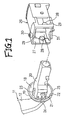
- a cover part 2 including a spherical-shaped outer surface is disposed on the base end portion of a lever 1 and two rotatably-supporting shaft portions 4 are respectively provided on and projected from the two mutually opposing side portions of a mounting part 3 projected from the interior of the cover portion 2.
- two recessed portions 5 for thickness reduction in the inner surface side of the cover part 2 in order to prevent a dent (a hollow) from being formed in the outer surface of the cover part 2.
- the present invention aims at eliminating the above drawback found in the conventional lever apparatus. Accordingly, it is an object of the invention to provide a lever apparatus for use in a vehicle which not only has a structure that a cover part including a spherical-shaped outer surface and two thickness-reducing recessed portions on the inner surface side thereof is formed in the base end portion of a lever but also can facilitate the manufacture of the lever.
- the invention is characterized by having the following arrangement.
- Fig. 2 shows the whole structure of a lever apparatus according to the present embodiment.
- This lever apparatus is to be mounted on the steering column portion of a car (vehicle) (not shown).
- a lever upper 12 and a lever lower 13 respectively made of synthetic resin and extending in the longitudinal direction of the lever apparatus 11 are disposed opposed to each other and are fitted with each other, thereby providing a hollow structure; and, on the leading end portion side thereof (in Fig. 2; on the left side), there are disposed a rotary switch 15 which can be operated by a rotary knob 14, and a push-button switch 17 to be operated by a push button 16.
- a cut-away portion 22 In the lower portion of the cover part 19 of the lever upper 12, there is formed a cut-away portion 22.
- a projecting portion 23 which extends so as to be continuous with the inner surface of the cover part 19. Further on the portions of the thickness-reducing recessed portions 18 that respectively correspond to the side portions of the mounting part 20, there are disposed reinforcing ribs 24.
- auxiliary cover part 25 including a spherical-shaped outer surface; and, when the lever upper 12 and lever lower 13 are combined together, the auxiliary cover part 25 is fitted into the cut-away portion 22 and thus the outer surface of the auxiliary cover part 25 becomes continuous with the outer surface of the cover part 19.
- the lever support member 26 is formed in a rectangular-shaped box and is also made of synthetic resin.
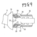
- the lever support member 26 is structured such that, in the surface thereof situated on the lever 11 side, there is formed an inserting opening 27, on the two mutually opposing sides thereof, there are respectively disposed rotating shaft portions 28 so as to project inwardly toward each other, and; in the peripheries of the two shaft portions 28, there are formed openings 29 respectively.
- a center shaft 30 so as to project upwardly and, on the lower-surface portion thereof, there is provided an arc-shaped rib 31 so as to project downwardly.
- the lever 11 structured by combining the lever upper 12 and lever lower 13 with each other, in case where the mounting part 20 situated on the base end portion side thereof is inserted into the inserting opening 27 of the lever support member 26 and, as shown in Fig. 4, the two fitting recessed portions 21 are respectively fitted with their corresponding shaft portions 28, the lever 11 can be rotatably mounted on the peripheries of the shaft portions 28 of the lever support member 26. Also, the lever 11 is mounted through the lever support member 26 on the steering column portion of a vehicle; and thus, in case where the lever 11 is rotated around the rotation shaft 30 of the lever support member 26, the lever 11 can be rotated around the rotation shaft 30 together with the lever support member 26.
- Fig. 5 shows a molding mold 35 which is used to mold the outer surface side portion of the cover part 19, a molding mold 36 used to mold the thickness-reducing recessed portions 18 and mounting portion 20 of the cover part 19, and liner molds 37, 37 respectively for molding the fitting recessed portions 21 of the cover part 19.
- the molding mold 35 is moved, for example, in the direction where it is moved away upwardly from the surface of the sheet of Fig. 5.
- the molding mold 36 is structured such that, after the liner molds 37, 37 are slided respectively in the arrow marks C1, C2 directions and are thereby retreated from their associated fitting recessed portions 21, the mold 36 is slided in the arrow mark C3 direction. With use of this mold structure, the base end portion of the lever upper 12 can be molded.
- the cover part 19 including a spherical-shaped outer surface and two thickness-reducing recessed portions 18 on the inner surface side thereof is disposed on the base end portion of the lever upper 12 of the lever 11, instead of the rotatably-supporting shaft portions which are formed in the conventional lever apparatus, the fitting recessed portions 21 are formed in the mounting part 20 of the lever upper 12. Thanks to this structure, in the neighboring portions of the openings of the thickness-reducing recessed portions 18, there are not any obstacles which can hinder the sliding motion of the molding mold. 36 for molding the thickness-reducing recessed portions 18. Therefore, when molding the lever upper 12, the molding mold 36 for molding the thickness-reducing recessed portions 18 can be slided in the projecting direction (in the arrow mark C direction) of the mounting part 20, which can facilitate the manufacture of the lever upper 12 and thus the lever 11.
- the shaft portions 28 can be made easy to be elastically deformed. Due to this, the shaft portions 28 and the peripheral portions of the shaft portions 28 can be prevented against breakage as much as possible.
- the cover part including a spherical-shaped outer surface and two thickness-reducing recessed portions on the inner surface side thereof is disposed on the base end portion of the lever
- the fitting recessed portions instead of the rotatably supporting shaft portions which are formed in the conventional lever apparatus, are formed in the mounting part of the lever. Thanks to this structure, the molding operation of the base end portion of the lever can be facilitated, which makes it possible to manufacture the lever.
Landscapes
- Engineering & Computer Science (AREA)
- Mechanical Engineering (AREA)
- Arrangement Or Mounting Of Control Devices For Change-Speed Gearing (AREA)
- Mechanical Control Devices (AREA)
Applications Claiming Priority (2)
| Application Number | Priority Date | Filing Date | Title |
|---|---|---|---|
| JP2002205534A JP4167020B2 (ja) | 2002-07-15 | 2002-07-15 | 車両用レバー装置 |
| JP2002205534 | 2002-07-15 |
Publications (3)
| Publication Number | Publication Date |
|---|---|
| EP1383021A2 true EP1383021A2 (de) | 2004-01-21 |
| EP1383021A3 EP1383021A3 (de) | 2010-02-17 |
| EP1383021B1 EP1383021B1 (de) | 2012-09-12 |
Family
ID=29774589
Family Applications (1)
| Application Number | Title | Priority Date | Filing Date |
|---|---|---|---|
| EP03016068A Expired - Lifetime EP1383021B1 (de) | 2002-07-15 | 2003-07-15 | Hebelvorrichtung für Kraftfahrzeuge |
Country Status (3)
| Country | Link |
|---|---|
| US (1) | US7357050B2 (de) |
| EP (1) | EP1383021B1 (de) |
| JP (1) | JP4167020B2 (de) |
Families Citing this family (1)
| Publication number | Priority date | Publication date | Assignee | Title |
|---|---|---|---|---|
| USD993198S1 (en) * | 2021-06-14 | 2023-07-25 | Custom Dynamics Llc | SXS switch |
Family Cites Families (15)
| Publication number | Priority date | Publication date | Assignee | Title |
|---|---|---|---|---|
| US2193230A (en) * | 1938-06-24 | 1940-03-12 | Packard Motor Car Co | Transmission control mechanism |
| US2290807A (en) * | 1940-09-09 | 1942-07-21 | Keeler Brass Co | Handle |
| US2342402A (en) * | 1941-05-26 | 1944-02-22 | Keeler Brass Co | Door handle |
| US2433993A (en) * | 1944-09-25 | 1948-01-06 | Keeler Brass Co | Hardware article |
| GB1188065A (en) * | 1968-03-01 | 1970-04-15 | Int Harvester Canada | Improvements in or relating to Gear Shifter Mechanisms |
| JP2585025Y2 (ja) * | 1993-09-28 | 1998-11-11 | 株式会社東海理化電機製作所 | ターンシグナルのキャンセル装置 |
| US5413008A (en) * | 1993-10-08 | 1995-05-09 | Grand Haven Stamped Products, Div. Of Jsj Corporation | Adjustment mechanism for rigid boot of a vehicle transmission shifter |
| US6286385B1 (en) * | 1997-12-02 | 2001-09-11 | Kabushiki Kaisha Tokai-Rika-Denki-Seisakusho | Shift lever device |
| JP3691241B2 (ja) * | 1998-02-27 | 2005-09-07 | ナイルス株式会社 | 車両用レバースイッチ |
| JP3784542B2 (ja) * | 1998-07-28 | 2006-06-14 | アルプス電気株式会社 | ターンシグナルスイッチ |
| JP3819630B2 (ja) * | 1999-03-12 | 2006-09-13 | アルプス電気株式会社 | ストークレバー |
| JP3854427B2 (ja) * | 1999-06-16 | 2006-12-06 | アルプス電気株式会社 | ターンシグナルスイッチ装置 |
| JP3921909B2 (ja) * | 2000-02-17 | 2007-05-30 | 松下電器産業株式会社 | レバースイッチ及びこれを用いた複合スイッチ |
| JP2003127762A (ja) * | 2001-10-19 | 2003-05-08 | Alps Electric Co Ltd | ターンシグナルスイッチ装置 |
| US7038580B2 (en) * | 2003-07-24 | 2006-05-02 | Alps Electric Co., Ltd. | Turn signal switch device |
-
2002
- 2002-07-15 JP JP2002205534A patent/JP4167020B2/ja not_active Expired - Fee Related
-
2003
- 2003-07-11 US US10/617,139 patent/US7357050B2/en not_active Expired - Lifetime
- 2003-07-15 EP EP03016068A patent/EP1383021B1/de not_active Expired - Lifetime
Non-Patent Citations (1)
| Title |
|---|
| None |
Also Published As
| Publication number | Publication date |
|---|---|
| EP1383021B1 (de) | 2012-09-12 |
| JP4167020B2 (ja) | 2008-10-15 |
| US20040074047A1 (en) | 2004-04-22 |
| JP2004046698A (ja) | 2004-02-12 |
| EP1383021A3 (de) | 2010-02-17 |
| US7357050B2 (en) | 2008-04-15 |
Similar Documents
| Publication | Publication Date | Title |
|---|---|---|
| GB2299576A (en) | Skin-covered lid | |
| EP0464831B1 (de) | Schaltknauf | |
| JPH058338Y2 (de) | ||
| US5305660A (en) | Shift knob | |
| EP0818378A2 (de) | Verkleidung für die Lenksäule eines Fahrzeugs | |
| JP2011216449A (ja) | 車両用室内灯具 | |
| US7357050B2 (en) | Lever apparatus for vehicles | |
| US5357823A (en) | Gearshift assembly for manual transmissions | |
| JPH0550530A (ja) | 空調用吹出口装置の二重射出成形方法 | |
| EP0679548A1 (de) | Dichtungsanordnung für den Schalthebel eines automatischen Getriebes | |
| US6675670B2 (en) | Automatic transmission operating lever | |
| JPH0280844A (ja) | 自動変速機のシフトレバー | |
| JPH043149Y2 (de) | ||
| JP3145667U (ja) | レジスタのダイヤルノブ装置 | |
| JP2007092244A (ja) | シールド板開閉式ヘルメット | |
| JPS6321479Y2 (de) | ||
| JPH0450373Y2 (de) | ||
| JPH07361Y2 (ja) | 車両用方向指示装置 | |
| JPH039049Y2 (de) | ||
| JP4049879B2 (ja) | スイッチ装置 | |
| JPH08150830A (ja) | ベンチレータルーバー構造 | |
| JP2000311554A (ja) | スイッチ装置 | |
| JPH0314336Y2 (de) | ||
| JPS6343539Y2 (de) | ||
| EP1528292B1 (de) | Wählhebeleinrichtung |
Legal Events
| Date | Code | Title | Description |
|---|---|---|---|
| PUAI | Public reference made under article 153(3) epc to a published international application that has entered the european phase |
Free format text: ORIGINAL CODE: 0009012 |
|
| AK | Designated contracting states |
Kind code of ref document: A2 Designated state(s): AT BE BG CH CY CZ DE DK EE ES FI FR GB GR HU IE IT LI LU MC NL PT RO SE SI SK TR |
|
| AX | Request for extension of the european patent |
Extension state: AL LT LV MK |
|
| PUAL | Search report despatched |
Free format text: ORIGINAL CODE: 0009013 |
|
| AK | Designated contracting states |
Kind code of ref document: A3 Designated state(s): AT BE BG CH CY CZ DE DK EE ES FI FR GB GR HU IE IT LI LU MC NL PT RO SE SI SK TR |
|
| AX | Request for extension of the european patent |
Extension state: AL LT LV MK |
|
| 17P | Request for examination filed |
Effective date: 20100413 |
|
| 17Q | First examination report despatched |
Effective date: 20100604 |
|
| AKX | Designation fees paid |
Designated state(s): DE FR |
|
| 17Q | First examination report despatched |
Effective date: 20110216 |
|
| GRAP | Despatch of communication of intention to grant a patent |
Free format text: ORIGINAL CODE: EPIDOSNIGR1 |
|
| GRAS | Grant fee paid |
Free format text: ORIGINAL CODE: EPIDOSNIGR3 |
|
| GRAA | (expected) grant |
Free format text: ORIGINAL CODE: 0009210 |
|
| AK | Designated contracting states |
Kind code of ref document: B1 Designated state(s): DE FR |
|
| REG | Reference to a national code |
Ref country code: DE Ref legal event code: R096 Ref document number: 60342065 Country of ref document: DE Effective date: 20121108 |
|
| PLBE | No opposition filed within time limit |
Free format text: ORIGINAL CODE: 0009261 |
|
| STAA | Information on the status of an ep patent application or granted ep patent |
Free format text: STATUS: NO OPPOSITION FILED WITHIN TIME LIMIT |
|
| 26N | No opposition filed |
Effective date: 20130613 |
|
| REG | Reference to a national code |
Ref country code: DE Ref legal event code: R097 Ref document number: 60342065 Country of ref document: DE Effective date: 20130613 |
|
| REG | Reference to a national code |
Ref country code: FR Ref legal event code: PLFP Year of fee payment: 14 |
|
| PGFP | Annual fee paid to national office [announced via postgrant information from national office to epo] |
Ref country code: FR Payment date: 20160613 Year of fee payment: 14 |
|
| PGFP | Annual fee paid to national office [announced via postgrant information from national office to epo] |
Ref country code: DE Payment date: 20160712 Year of fee payment: 14 |
|
| REG | Reference to a national code |
Ref country code: DE Ref legal event code: R119 Ref document number: 60342065 Country of ref document: DE |
|
| REG | Reference to a national code |
Ref country code: FR Ref legal event code: ST Effective date: 20180330 |
|
| PG25 | Lapsed in a contracting state [announced via postgrant information from national office to epo] |
Ref country code: DE Free format text: LAPSE BECAUSE OF NON-PAYMENT OF DUE FEES Effective date: 20180201 |
|
| PG25 | Lapsed in a contracting state [announced via postgrant information from national office to epo] |
Ref country code: FR Free format text: LAPSE BECAUSE OF NON-PAYMENT OF DUE FEES Effective date: 20170731 |