EP1384643A2 - Steering column and method for adjusting a steering column - Google Patents
Steering column and method for adjusting a steering column Download PDFInfo
- Publication number
- EP1384643A2 EP1384643A2 EP03017865A EP03017865A EP1384643A2 EP 1384643 A2 EP1384643 A2 EP 1384643A2 EP 03017865 A EP03017865 A EP 03017865A EP 03017865 A EP03017865 A EP 03017865A EP 1384643 A2 EP1384643 A2 EP 1384643A2
- Authority
- EP
- European Patent Office
- Prior art keywords
- steering column
- devices
- occupant
- column according
- load
- Prior art date
- Legal status (The legal status is an assumption and is not a legal conclusion. Google has not performed a legal analysis and makes no representation as to the accuracy of the status listed.)
- Granted
Links
- 238000000034 method Methods 0.000 title claims abstract description 23
- 239000000725 suspension Substances 0.000 claims abstract description 42
- 238000001514 detection method Methods 0.000 claims abstract description 32
- 230000001960 triggered effect Effects 0.000 claims abstract description 15
- 238000013016 damping Methods 0.000 claims abstract description 12
- 238000010521 absorption reaction Methods 0.000 claims description 13
- 230000000694 effects Effects 0.000 claims description 4
- 230000003287 optical effect Effects 0.000 claims description 4
- 238000012546 transfer Methods 0.000 claims description 3
- 238000011161 development Methods 0.000 description 9
- 239000002360 explosive Substances 0.000 description 7
- 238000013461 design Methods 0.000 description 5
- 230000007246 mechanism Effects 0.000 description 5
- 230000008901 benefit Effects 0.000 description 4
- 206010000369 Accident Diseases 0.000 description 3
- 230000001419 dependent effect Effects 0.000 description 3
- 238000010586 diagram Methods 0.000 description 3
- 230000009467 reduction Effects 0.000 description 3
- 238000004904 shortening Methods 0.000 description 3
- 238000006073 displacement reaction Methods 0.000 description 2
- 238000012544 monitoring process Methods 0.000 description 2
- 208000027418 Wounds and injury Diseases 0.000 description 1
- 238000013459 approach Methods 0.000 description 1
- 230000000903 blocking effect Effects 0.000 description 1
- 238000010276 construction Methods 0.000 description 1
- 230000006378 damage Effects 0.000 description 1
- 230000003111 delayed effect Effects 0.000 description 1
- 208000014674 injury Diseases 0.000 description 1
- 238000009434 installation Methods 0.000 description 1
- 238000012986 modification Methods 0.000 description 1
- 230000004048 modification Effects 0.000 description 1
- 238000006467 substitution reaction Methods 0.000 description 1
Images



Classifications
-
- B—PERFORMING OPERATIONS; TRANSPORTING
- B62—LAND VEHICLES FOR TRAVELLING OTHERWISE THAN ON RAILS
- B62D—MOTOR VEHICLES; TRAILERS
- B62D1/00—Steering controls, i.e. means for initiating a change of direction of the vehicle
- B62D1/02—Steering controls, i.e. means for initiating a change of direction of the vehicle vehicle-mounted
- B62D1/16—Steering columns
- B62D1/18—Steering columns yieldable or adjustable, e.g. tiltable
- B62D1/19—Steering columns yieldable or adjustable, e.g. tiltable incorporating energy-absorbing arrangements, e.g. by being yieldable or collapsible
- B62D1/195—Yieldable supports for the steering column
-
- F—MECHANICAL ENGINEERING; LIGHTING; HEATING; WEAPONS; BLASTING
- F16—ENGINEERING ELEMENTS AND UNITS; GENERAL MEASURES FOR PRODUCING AND MAINTAINING EFFECTIVE FUNCTIONING OF MACHINES OR INSTALLATIONS; THERMAL INSULATION IN GENERAL
- F16F—SPRINGS; SHOCK-ABSORBERS; MEANS FOR DAMPING VIBRATION
- F16F7/00—Vibration-dampers; Shock-absorbers
- F16F7/12—Vibration-dampers; Shock-absorbers using plastic deformation of members
- F16F7/127—Vibration-dampers; Shock-absorbers using plastic deformation of members by a blade element cutting or tearing into a quantity of material; Pultrusion of a filling material
Definitions
- the invention relates to a steering column according to the preamble of claim 1 and an adjustment method for a steering column according to the preamble of claim 26.
- the older German utility model applications based on the present applicant / owner 298 08 317.5, 299 01 657.9 and 299 00 289.6 and the one based thereon PCT registration PCT / DE 99/01000 generally deal with a safety steering column, a security system for a vehicle, a vehicle with a security system, and a safety procedure to protect occupants in the event of an accident.
- the present The invention relates to improvements to all of those discussed in the earlier application Techniques and exemplary embodiments, in particular with regard to the triggering control of the Steering column and especially for different occupants and belt conditions.
- the complete Disclosure content of these older applications, particularly with regard to triggering control the steering column and specifically for different occupants and belt conditions fully incorporated into the available documents by the references.
- a vehicle steering column is known, for example, from the older applications mentioned, which is adjusted in the event of an accident so that the steering wheel end of one Occupants is moved away.
- a steering device for a vehicle is known, one Steering column and / or a steering wheel moved in the event of a crash in the vehicle front direction becomes.
- This steering column is supported on the vehicle body by a force limiter.
- the Force-displacement identification of the force limiter can be influenced via a throttle valve, which is controlled by a Control unit can be acted upon.
- For influencing the force-displacement identifier of the Force limiters can take different parameters into account individually or in combination be such.
- WO 98/58831 A discloses a steering column for a vehicle with a two-part steering column holder and an energy absorption mechanism between the two parts thereof.
- This energy absorption mechanism includes two or more longitudinal grooves and one Cutting member that is designed to run along one of the grooves when relative adjustment occurs between the two parts of the steering column bracket.
- a steering column for a vehicle is known from WO 98/22325 A, the steering column is adjustable in the event of an accident with respect to a load suspension structure, namely under Use of a first energy absorption unit to absorb energy during the Verstellens. Furthermore, a sensor for detecting a state is provided that is representative for that is that an occupant has put on a belt. It is also between the steering column and a second energy absorption unit is arranged in the load suspension structure and is the Sensor connected to a blocking unit, which is designed so that when the above Condition is detected, an adjustment of the second energy absorption unit compared to the Allows load absorption structure, whereby energy is absorbed.
- the present invention aims to protect this steering column and its adjustment method to further improve the occupants and especially the retraction behavior of a steering column in an accident to be optimally designed depending on the situation and reliably.
- This goal is achieved with a steering column according to claim 1 and an adjustment method for reached a steering column according to claim 26.
- a steering column for a vehicle is created, with adjusting devices, which can be triggered in the event of an accident, around at least one steering wheel end region to move the steering column away from an occupant, the adjusting devices Load suspension devices for damping movement of at least the steering wheel end region the steering column away from an occupant and for at least two modes of operation are designed, and wherein a controller for detecting occupant parameters by means of detection devices and triggering an operating mode of the adjusting devices depending is provided by the occupant parameters, and further the load suspension devices Deformation devices included that are dependent on the controller from the occupant's parameters to implement a specific operating mode of the adjustment devices can be brought into or out of effect, and at least the deformation devices a cutting knife cutting along a movement path for load absorption included, which can be brought into a load suspension position by tilting.
- each cutting knife a tipping point is mounted so that it cuts in when the adjustment devices are driven.
- This can be developed in that each cutting knife in a slot an inner tube ring piston of the steering column is mounted on a tilting point such that it when the adjustment devices are driven via the inner tube ring piston into a wall cuts a steering column outer tube of the steering column.
- each cutting knife has a Stop is assigned by which the cutting depth of the chip is determined.
- a pressurized one for the at least one cutting knife Control pin is provided through which the tilting of the cutting knife into the load-bearing position is preventable.
- a pressurized control pin is provided for the at least one cutting knife which is designed to tilt the cutting knife out of function in order to take up the load to dub.
- the adjusting devices for causing the movement of at least the steering wheel end region the steering column away from an occupant and that the drive devices in the event of an accident, depending on the occupant parameters can be triggered.
- the drive devices contain a pyrotechnic gas generator and / or can be triggered electrically are.
- the load suspension devices at least contain two stages, depending on the control in the event of an accident can be operated directly or indirectly by the occupant parameters, preferably the steps of the load suspension devices individually, each with different load suspension properties and / or can be operated simultaneously with added load suspension properties are.
- the load suspension devices or, if necessary, each step individually depending on the control in the event of an accident can be switched off directly or indirectly from the occupant parameters. More with these Versions that can be combined are that the load suspension devices or possibly a step thereof deformation devices, in particular with along a movement path cutting blades, and / or braking devices, in particular a brake carriage with preferably at least two braking force levels.
- control can preferably be used to trigger the drive devices depending on the seating position of the occupant and especially for Detection of a predeterminable distance or falling below a predeterminable distance the position of the seat for the occupant from the steering wheel by means of the detection devices be designed.
- control for Triggering such an operating mode of the adjusting devices is designed, in which In the event of an accident in the case of a predeterminable distance or a shortfall a predetermined distance of the position of the seat for the occupant from the steering wheel Drive devices of the adjustment devices are triggered.
- the controller for operating the load suspension devices or, if necessary, each step individually depending on the state of the belt and / or the Sitting position of the occupant is designed, the controller in particular to trigger a such operating mode of the adjusting devices is designed in the event of an accident in the case of a non-belted occupant, the load suspension devices or at least one Level of which are effective.
- the control can be used to trigger a be designed such operating mode of the adjustment devices, in which in the case of a Accident when a predeterminable distance is recorded or a value is undershot Predeterminable distance of the position of the seat for the occupant from the steering wheel the load suspension devices or at least one stage of it is / is ineffective.
- the detection devices position detection devices of the seat for the occupant, condition detection devices of the belt buckle for the seat belt of the occupant, height, weight and / or posture detection devices contained regarding the occupant.
- the position detection devices can the seat for the occupant, in particular at least one electrical or optical switch contained in or in connection with seat guide rails, and / or the condition detection devices the buckle for the seat belt of the occupant at least one electrical or optical lock usage switch included.
- the object of the present invention specified above is also achieved with an adjustment method for a steering column of a vehicle, in the event of an accident, at least one end of the steering wheel of the steering column is moved away from an occupant by means of adjusting devices, occupant parameters are detected by means of detection devices, and wherein the movement of at least the steering wheel end region of the steering column away from the occupant takes place by means of a control as a function of the occupant parameters in accordance with an operating mode of a plurality of operating modes of the adjusting devices, and furthermore to implement a specific operating mode of the adjusting devices by means of the control, depending on the occupant parameters, deformation devices for movement-damping load suspension are brought into or out of effect, and, if the deformation devices are effective, in the event of an accident, at least cutting cutting knife of the deformation devices for movement-damping load suspension is adjusted along a movement path by tilting into a load suspension position.
- each cutting knife a tipping point is mounted so that it cuts in when the adjustment devices are driven.
- each cutting knife is in one Slit of an inner tube ring piston of the steering column mounted in such a way on a tipping point is that when the adjustment devices are driven via the inner tube ring piston, it is deliberately integrated into a Cut wall of a steering column outer tube of the steering column.
- Another development is that the cutting depth of the chip of each cutting knife is determined by a stop.
- the cutting knife is tilted into the load suspension position is prevented by a pressurized control pin.
- the at least one cutting knife by a pressurized control pin is tilted out of function in order to transfer the load suspension.
- a drive of the adjusting devices can preferably also be used to effect the movement at least the steering wheel end region of the steering column away from the occupant in the event of a Accident triggered depending on the occupant parameters and / or at least a movement the steering wheel end area of the steering column away from an occupant in the event of an accident depending on the occupant parameters.
- a further development of the last-mentioned method variant involves damping the movement at least the steering wheel end region of the steering column away from an occupant in the event of a Accident depending on the occupant parameters, in particular optionally in individual Stages switched off.
- the sitting position, the state of the seat belt, the size, the weight and / or the posture of the occupant as occupant parameters to be recorded.
- the adjustment devices in Depending on the seating position of the occupant are driven, in particular the Adjustment devices in the event of an accident at a predetermined distance or a detected detected falling below a predetermined distance of the position of the seat for the occupant are not driven by the steering wheel according to an operating mode.
- the adjustment devices can be dependent on the state of the seat belt and / or be cushioned from the seating position of the occupant.
- the present invention thus provides a steering column and an adjustment method for a steering column according to earlier applications mentioned in the introduction in an advantageous manner further improved.
- one of the two load limits e.g. load receiver A
- the weight detection of the tall driver and the position detection e.g. a small one
- Drivers can of course also use electronic weight and position sensors, which are currently be developed in many places, or other suitable ones, to the person skilled in the art without further ado known or accessible species are identified.
- a steering column 1 for a vehicle (not shown), which is only indicated, has a conventional one telescopic structure, due to its popularity in numerous versions is not further discussed here, since the present invention applies to all known Designs also retractable overall, not telescopically collapsible Steering columns can be used and the present invention is not the actual design relates to such steering columns.
- the steering column 1 has a steering wheel end area 2 and is provided with adjusting devices 3 provided, which can be triggered in the event of an accident to at least the To move the steering wheel end region 2 of the steering column 1 away from an occupant (not shown), who sits on a seat 4.
- the adjusting devices 3 are illustrated in the figure for the three Operating modes designed.
- a controller 5 detects occupant parameters by means of detection devices 6 and triggers an operating mode depending on the occupant parameters Adjustment devices 3 from.
- the adjustment devices 3 contain load suspension devices 7 with a first and a second load suspension device or limiter 8 (A) or 9 (B), each with its own bolt 10 and 11 and a common load-bearing plate 12 contain the deformation devices (D) form.
- the load receiving plate 12 With one Carriage 13 connected.
- the load receiving plate 12 is with a telescopic part (not shown) the steering column 1 is firmly connected, and the carriage 13 is with the other telescopic part (not shown) of the steering column 1 firmly connected.
- the bolts 10 and 11 each have an explosive charge S, which the controller 5, which, for example, is connected to or integrated in an overall control system (not shown) for an airbag, each of which can be ignited independently of one another, to render each of the bolts 10 and 11 ineffective accordingly.
- the controller 5 To the controller 5 are as detection devices 6 state detection devices 13 of a belt buckle 14 connected in the form of a belt or buckle switch 15. This belt usage switch 15 results in a belt usage signal when the occupant is wearing his seat belt (not shown). If the belt usage signal is not generated, it is Control informs that the occupant is not properly buckled up.
- position detection devices 16 are contained in the detection devices 6, which are formed by a position switch 17 in a seat rail 18 of the seat 4.
- This position switch 17 leads to a near position signal when the seat 4 is in the position the position switch 17 has reached or closer than the position switch 17 on the steering column 1 is.
- the controller 5 receives the information that the occupant is one small person acts. If the near position signal is not generated, the control is above it informs that the occupant is a tall person.
- controller 5 set each of the three operating modes of the adjusting devices 3 according to FIG. 1.
- the controller 5 If the controller 5 has received the near position signal, it initiates the operating mode for a buckled or unbuckled "little woman".
- the controller fires in this mode 5 the explosive charges S of the two bolts 10 and 11, so that they become ineffective and the load receiving plate 12 and the slide 13 are decoupled.
- the controller also fires 5 shows a pyrotechnic explosive device 19 of a gas generator 20, and the one generated by it Gas acts on a piston 21 with a piston rod 22 connected to the end of the steering wheel 2 containing telescopic part (not shown) of the steering column 1 firmly connected is that the two telescopic parts (not shown) of the steering column 5 are pulled together.
- the parts 19 to 22 are components of the adjusting devices 3 and form together Drive devices 23.
- the controller 5 If the controller 5 has not received the near position signal, it checks whether the belt usage signal given is. If the belt usage signal is present, the controller 5 initiates the Operating mode for a buckled "big man". The controller fires in this mode 5 the explosive charge S only of the bolt 11, so that only this is ineffective and that Load receiving plate 12 and the carriage 13 are still coupled by the bolt 10.
- the Load suspension device 8 (A) is thus effective to dissipate energy that occurs when the seat belt strikes "Big man” occurs on the steering wheel (not labeled).
- the drive devices 23 are not triggered.
- the controller 5 If the controller 5 receives neither the near position signal nor the belt usage signal, the controller 5 thus initiates the operating mode for an unbuckled "tall man". In this mode, the controller 5 does not ignite an explosive charge S, so that the load-receiving plate 12 and the carriage 13 are coupled by both bolts 10 and 11.
- the load lifter 8 (A) and the load receiver 9 (B) are thus effective to dissipate energy that Impact of the unbuckled "big man” on the steering wheel (not labeled) occurs.
- the drive devices 23 are not triggered.
- Signal lines between the controller 5 and the explosive charges S, the pyrotechnic The explosive device 19 and the detection devices 6 are shown as lines or lines in FIG. 2 located.
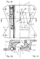
- 3a, 3b and 3c show a carriage 13 for receiving the steering (not shown) in its carriage holder 24 in Fig. 3a left from below and right from above and in the 3b and 3c each cut.
- the pyrotechnic gas generator 20 of the drive devices 23 is attached to the carriage receptacle 24 on the one hand and to the carriage 13 on the other hand.
- the load receiver 8 (A) and the load receiver 9 (B) are on the right side of FIG. 3a. shown in one piece in installation position.
- the load suspension devices 8 and 9 are on the one hand with the bolts 10 or 11 on the slide 13 and on the other hand on the slide receptacle 24 with screw connections 25 provided.
- the sliding telescopic part (not shown) of the steering column 1 is in the Recess L fixed.
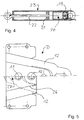
- the drive devices 23 are shown separately in FIG. 4, as they are already in connection were explained with FIG. 2.
- FIG. 5 shows above, i.e. in a ready-to-install condition, and below after actuation both load suspension 8 and 9, the load receiving plate 12, which is a stamped part is.
- the load limiter 8 (A) is designed such that it is by means of of the bolt 10 immediately tears at tear lines 26 when the load is exceeded. there the end of the load limiter 8 (A) inevitably slides over the load limiter 9 (B), whose bolt 11 initially moves in a slot 27 of the load limiter 9 (B).
- This Design advantageously leads to the pull-out forces of the two load sensors Add 8 (A) and 9 (B). If they ripped apart in parallel, only one would of the two load hanger A or B.
- the invention thus in particular makes a safety steering column created with a crash sled that has two load sensors for buckled and not buckled tall and small people.
- a control with a lock usage switch is a control with a lock usage switch.
- the crash slide for small people is called “Ab-. stationary sled "and its load sensors are taken out of operation Smaller people can preferably use an electrical seat position detection.
- the load suspension devices are of this type are built in a row, e.g. by means of a slot in a connection to the delayed Start-up that the load frames add up with the load.
- this embodiment relates to a safety steering column with pyrotechnic driven shortening for small drivers and peak load reduction for large drivers.
- this embodiment relates to a safety steering column with pyrotechnic driven shortening for small drivers and peak load reduction for large drivers.
- Steering columns are already partially supplemented to an airbag with a peak load reduction equipped for heavy persons.
- Practice has also shown that small and too dense Drivers positioned on the airbag may die to some extent as a result.
- the second embodiment also creates a solution for reducing peak loads for large drivers and in same system a shortening of the steering column for small drivers in the event of an accident.
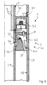
- 6 to 8 show a steering column outer tube 28 and a steering column inner tube 29, which Represent telescopic parts of a steering column 1, the steering column inner tube 29 the steering wheel end region 2 of the steering column 1 contains.
- On the steering column outer tube 28 is an outer tube ring piston 30 attached, for example, by a clinch connection 31.
- the outer tube ring piston 30 contains a pyrotechnic cartridge 32 which is connected to control cables K with the control 5 (see Fig. 2) is connected.
- With the steering column inner tube 29 is an inner tube ring piston 33 firmly connected by a clinching connection 34 as well.
- This inner tube ring piston 33 contains one or more in slots in the second embodiment 35 mounted, correspondingly shaped cutting knife 36 as parts of deformation devices 6.
- the cutting knives 36 are mounted on a "tipping point" 37 such that they are at Drive via the inner tube ring piston 33 into the wall 38 of the steering column outer tube Cut 28 of the steering column 1.
- the cutting depth 39 of the chip 40 is by a correspondingly shaped stop 41 determined.
- the size of the chip 40 is proportional to that desired load bearing.
- the deformation devices 6 form load receivers 42.
- the outer tubular ring piston 30 and the inner tubular ring piston 33 form drive devices 23, which, like the load receivers 42, are components of the adjusting devices 3 of the Steering column 1 are.
- Fig. 7 shows the function with small drivers.
- the charge 43 presses the pyrotechnic Cartridge 32 connects the inner tube ring piston 33 to the steering column inner tube 29 down and away from an occupant (not shown).
- the pyrotechnic Cartridge 32 connects the inner tube ring piston 33 to the steering column inner tube 29 down and away from an occupant (not shown).
- one pressurized control pin 44 tilting the cutter 36 into position "Load bearing", i.e. for chip removal in the wall 38 of the steering column outer tube 28 the steering column 1.
- FIGS. 6 to 8 explain the invention as follows:
- Steering column tubes that can be pushed into each other are provided with “ring pistons", which are used by small drivers shorten the steering column by means of a pyrotechnic pressure build-up and to bring an inflating airbag a greater distance.
- ring pistons In one of the ring pistons a load-bearing mechanism is built in, which is used by tall drivers instead of shortening the steering column is effective and for small drivers using pyrotechnic pressure Function is set.
- the second ring piston is equipped with a load suspension mechanism. In the example shown, these are appropriately shaped and stored tiltable Knife. It can also be corrugated pipes, material-deforming balls or similar. act (in the figures not shown).
- the function of the load-bearing ring piston is fundamentally such that it automatically picks up and breaks down load when the inner steering column tube is relative is moved to the outside.
- the knife is machined into the outside Steering column tube pressed.
- this load pick-up can be used with a pyrotechnic ignition with the appropriate performance "overplayed", or the "knife” as in the example tilted out of function by a pressurized control pin.
- the inner and outer steering column tube designed for the largest possible difference in diameter.
- the outer steering column tube is positioned in bearings (not shown in the figures).
- the inner Steering column tube is form-fitting to the outside with corresponding ring pistons (grooves / shape) connected.
- the pair of ring pistons is e.g. by linking with one outer and one each inner tube connected.
- An annular piston contains a pyrotechnic charge, the pressure of which press the ring pistons away from each other and thus shorten the steering column or the steering wheel can pull away from the occupant in the direction of travel.
- Small drivers can also be found in the second embodiment example e.g. through appropriate electronic monitoring systems or seat position detection using switches in the seat rail.
Landscapes
- Engineering & Computer Science (AREA)
- General Engineering & Computer Science (AREA)
- Mechanical Engineering (AREA)
- Chemical & Material Sciences (AREA)
- Combustion & Propulsion (AREA)
- Transportation (AREA)
- Steering Controls (AREA)
- Air Bags (AREA)
Abstract
Description
Die Erfindung betrifft eine Lenksäule nach dem Oberbegriff des Anspruchs 1 sowie ein Verstellverfahren
für eine Lenksäule nach dem Oberbegriff des Anspruchs 26.The invention relates to a steering column according to the preamble of
Die auf den vorliegenden Anmelder/Inhaber zurückgehenden älteren deutschen Gebrauchsmusteranmeldungen 298 08 317.5, 299 01 657.9 und 299 00 289.6 sowie die darauf beruhende PCT-Anmeldung PCT/DE 99/01000 befassen sich allgemein mit einer Sicherheitslenksäule, einem Sicherheitssystem für ein Fahrzeug, einem Fahrzeug mit einem Sicherheitssystem sowie einem Sicherheitsverfahren, jeweils um Insassen bei einem Unfall zu schützen. Die vorliegende Erfindung betrifft Verbesserungen sämtlicher in der früheren Anmeldung behandelten Techniken und Ausführungsbeispiele insbesondere hinsichtlich der Auslösesteuerung der Lenksäule und speziell für verschiedene Insassen und Angurtzustände. Insofern ist der vollständige Offenbarungsgehalt dieser älteren Anmeldungen insbesondere hinsichtlich der Auslösesteuerung der Lenksäule und speziell für verschiedene Insassen und Angurtzustände hiermit durch die Bezugnahmen vollumfänglich in die vorliegenden Unterlagen aufgenommen.The older German utility model applications based on the present applicant / owner 298 08 317.5, 299 01 657.9 and 299 00 289.6 and the one based thereon PCT registration PCT / DE 99/01000 generally deal with a safety steering column, a security system for a vehicle, a vehicle with a security system, and a safety procedure to protect occupants in the event of an accident. The present The invention relates to improvements to all of those discussed in the earlier application Techniques and exemplary embodiments, in particular with regard to the triggering control of the Steering column and especially for different occupants and belt conditions. In this respect, the complete Disclosure content of these older applications, particularly with regard to triggering control the steering column and specifically for different occupants and belt conditions fully incorporated into the available documents by the references.
Beispielsweise aus den genannten älteren Anmeldungen ist eine Fahrzeug-Lenksäule bekannt, die im Falle eines Unfalls so verstellt wird, dass jedenfalls das lenkradseitige Ende von einem Insassen weg bewegt wird.A vehicle steering column is known, for example, from the older applications mentioned, which is adjusted in the event of an accident so that the steering wheel end of one Occupants is moved away.
Aus der DE 198 29 237 A1 ist eine Lenkvorrichtung für ein Fahrzeug bekannt, wobei eine Lenksäule und/oder ein Lenkrad in einem Crashfall in Fahrzeugfrontrichtung verschoben wird. Diese Lenksäule ist über einen Kraftbegrenzer am Fahrzeugaufbau abgestützt. Die Kraft-Weg-Kennung des Kraftbegrenzers ist über ein Drosselventil beeinflußbar, das von einer Steuereinheit beaufschlagbar ist. Für die Beeinflussung der Kraft-Weg-Kennung des Kraftbegrenzers können unterschiedliche Parameter einzeln oder in Kombination berücksichtigt werden, wie z. B. Insassengewicht, Position eines Fahrzeugsitzes oder Rücklehnenneigung des Fahrzeugsitzes, soweit Insassenparameter betroffen sind. From DE 198 29 237 A1 a steering device for a vehicle is known, one Steering column and / or a steering wheel moved in the event of a crash in the vehicle front direction becomes. This steering column is supported on the vehicle body by a force limiter. The Force-displacement identification of the force limiter can be influenced via a throttle valve, which is controlled by a Control unit can be acted upon. For influencing the force-displacement identifier of the Force limiters can take different parameters into account individually or in combination be such. B. occupant weight, position of a vehicle seat or backrest inclination of the vehicle seat as far as occupant parameters are concerned.
Die WO 98/58831 A offenbart eine Lenksäule für ein Fahrzeug mit einer zweiteiligen Lenksäulenhalterung und einem Energiebabsorptionsmechanismus zwischen den beiden Teilen davon. Dieser Energiebabsorptionsmechanismus enthält zwei oder mehr Längsnute und ein Schneideglied, das ausgelegt ist, längs einer der Nute zu laufen, wenn eine relative Verstellung zwischen den beiden Teilen der Lenksäulenhalterung auftritt. Ferner sind Einrichtungen enthalten, um das Schneideglied auf eine vorgegebene Nut einzustellen, wobei wenigstens zwei Nute bezüglich einander unterschiedliche Deformationswiderstände haben, wodurch der Deformationswiderstand in dem Energiebabsorptionsmechanismus durch Einstellen des Schneidegliedes auf eine vorgegebene Nut eingestellt werden kann.WO 98/58831 A discloses a steering column for a vehicle with a two-part steering column holder and an energy absorption mechanism between the two parts thereof. This energy absorption mechanism includes two or more longitudinal grooves and one Cutting member that is designed to run along one of the grooves when relative adjustment occurs between the two parts of the steering column bracket. There are also facilities included to adjust the cutting link to a predetermined groove, at least have two grooves with respect to each other different deformation resistances, whereby the Deformation resistance in the energy absorption mechanism by adjusting the Cutting link can be set to a predetermined groove.
Ferner ist aus der WO 98/22325 A eine Lenksäule für ein Fahrzeug bekannt, wobei die Lenksäule im Fall eines Unfalls bezüglich einer Lastaufnahmestruktur verstellbar ist, und zwar unter Nutzung einer ersten Energieabsorptionseinheit zur Absorption von Energie während des Verstellens. Weiterhin ist ein Sensor zum Detektieren eines Zustandes vorgesehen, der repräsentativ dafür ist, dass ein Insasse einen Gurt angelegt hat. Femer ist zwischen der Lenksäule und der Lastaufnahmestruktur eine zweite Energieabsorptionseinheit angeordnet und ist der Sensor an eine Blockiereinheit angeschlossen, die so ausgelegt ist, dass sie, wenn der obige Zustand detektiert wird, ein Verstellen der zweiten Energieabsorptionseinheit gegenüber der Lastaumahmestruktur zuläßt, wodurch Energie absorbiert wird.Furthermore, a steering column for a vehicle is known from WO 98/22325 A, the steering column is adjustable in the event of an accident with respect to a load suspension structure, namely under Use of a first energy absorption unit to absorb energy during the Verstellens. Furthermore, a sensor for detecting a state is provided that is representative for that is that an occupant has put on a belt. It is also between the steering column and a second energy absorption unit is arranged in the load suspension structure and is the Sensor connected to a blocking unit, which is designed so that when the above Condition is detected, an adjustment of the second energy absorption unit compared to the Allows load absorption structure, whereby energy is absorbed.
Die vorliegende Erfindung hat das Ziel, diese Lenksäule und ihr Verstellverfahren zum Schutz der Insassen weiter zu verbessern und insbesondere das Rückziehverhalten einer Lenksäule bei einem Unfall situationsabhängig und zuverlässig optimal zu gestalten.The present invention aims to protect this steering column and its adjustment method to further improve the occupants and especially the retraction behavior of a steering column in an accident to be optimally designed depending on the situation and reliably.
Dieses Ziel wird mit einer Lenksäule nach dem Anspruch 1 und einem Verstellverfahren für
eine Lenksäule nach dem Anspruch 26 erreicht.This goal is achieved with a steering column according to
Im Rahmen der Erfindung wird eine Lenksäule für ein Fahrzeug geschaffen, mit Verstelleinrichtungen, die im Falle eines Unfalls auslösbar sind, um zumindest einen Lenkrad-Endbereich der Lenksäule von einem Insassen weg zu bewegen, wobei die Verstelleinrichtungen Lastaufnahmeeinrichtungen zum Dämpfen einer Bewegung zumindest des Lenkrad-Endbereiches der Lenksäule von einem Insassen weg enthalten und für wenigstens zwei Betriebsmodi ausgelegt sind, und wobei eine Steuerung zum Erfassen von Insassenparametem mittels Detektionseinrichtungen und Auslösen eines Betriebsmodus der Verstelleinrichtungen in Abhängigkeit von den Insassenparametern vorgesehen ist, und wobei ferner die Lastaufilahmeeinrichtungen Deformationseinrichtungen enthalten, die mittels der Steuerung in Abhängigkeit von den Insassenpararnetern zur Realisierung eines bestimmten Betriebsmodus der Verstelleinrichtungen in oder ausser Wirkung bringbar sind, und die Deformationseinrichtungen wenigstens ein längs eines Bewegungsweges zur Lastaufnahme spanabhebendes Schneidmesser enthalten, das durch Kippen wahlweise in eine Lastaufnahmestellung bringbar ist.Within the scope of the invention, a steering column for a vehicle is created, with adjusting devices, which can be triggered in the event of an accident, around at least one steering wheel end region to move the steering column away from an occupant, the adjusting devices Load suspension devices for damping movement of at least the steering wheel end region the steering column away from an occupant and for at least two modes of operation are designed, and wherein a controller for detecting occupant parameters by means of detection devices and triggering an operating mode of the adjusting devices depending is provided by the occupant parameters, and further the load suspension devices Deformation devices included that are dependent on the controller from the occupant's parameters to implement a specific operating mode of the adjustment devices can be brought into or out of effect, and at least the deformation devices a cutting knife cutting along a movement path for load absorption included, which can be brought into a load suspension position by tilting.
Damit kann auf unterschiedliche Umstände, wie beispielsweise einen grossen nicht angegurteten Fahrer, einen grossen angegurteten Fahrer, einen kleinen angegurteten Fahrer, etc. Rücksicht genommen und im Falle eines Unfalls eine jeweils optimale Lenksäulenverstellung durchgeführt werden.This allows for different circumstances, such as a large non-belted one Driver, a big belted driver, a small belted driver, etc. Consider taken and in the event of an accident an optimal steering column adjustment be performed.
Eine vorteilhafte und bevorzugte Weiterbildung besteht darin, dass jedes Schneidmesser auf einem Kipppunkt gelagert ist, so dass es bei Antrieb der Verstelleinrichtungen gezielt einschneidet. Dies kann dadurch weitergebildet sein, dass jedes Schneidmesser in einem Schlitz eines Innenrohr-Ringkolbens der Lenksäule derart auf einem Kipppunkt gelagert ist, dass es bei Antrieb der Verstelleinrichtungen über den Innenrohr-Ringkolben gezielt in eine Wandung eines Lenksäulenaussenrohrs der Lenksäule einschneidet.An advantageous and preferred development is that each cutting knife a tipping point is mounted so that it cuts in when the adjustment devices are driven. This can be developed in that each cutting knife in a slot an inner tube ring piston of the steering column is mounted on a tilting point such that it when the adjustment devices are driven via the inner tube ring piston into a wall cuts a steering column outer tube of the steering column.
Bei einer anderen bevorzugten Weiterbildung ist vorgesehen, dass jedem Schneidmesser ein Anschlag zugeordnet ist, durch den die Schneidtiefe des Spanes bestimmt ist. alternativ oder zusätzlich kann vorgesehen sein, dass für das wenigstens eine Schneidmesser ein druckbeaufschlagter Steuerstift vorgesehen ist, durch den das Kippen des Schneidemessers in die Lastaufnahmestellung verhinderbar ist. Statt der letzten Ausgestaltungsvariante ist es auch von Vorteil, wenn für das wenigstens eine Schneidmesser ein druckbeaufschlagter Steuerstift vorgesehen ist, der ausgelegt ist, das Schneidmesser außer Funktion zu kippen, um die Lastaufnahme zu überspielen.Another preferred development provides that each cutting knife has a Stop is assigned by which the cutting depth of the chip is determined. alternatively or In addition, provision can be made for a pressurized one for the at least one cutting knife Control pin is provided through which the tilting of the cutting knife into the load-bearing position is preventable. Instead of the last design variant, it is also from Advantage if a pressurized control pin is provided for the at least one cutting knife which is designed to tilt the cutting knife out of function in order to take up the load to dub.
Vorzugsweise ist bei einer erfindungsgemäßen Lenksäule ferner vorgesehen, dass die Verstelleinrichtungen Antriebseinrichtungen zum Bewirken der Bewegung zumindest des Lenkrad-Endbereiches der Lenksäule von einem Insassen weg enthalten, und dass die Antriebseinrichtungen im Falle eines Unfalls von der Steuerung in Abhängigkeit von den Insassenparametern auslösbar sind. Eine bevorzugte Weiterbildung davon besteht darin, dass die Antriebseinrichtungen einen pyrotechnischen Gasgenerator enthalten und/oder elektrisch auslösbar sind.In a steering column according to the invention, it is preferably also provided that the adjusting devices Drive devices for causing the movement of at least the steering wheel end region the steering column away from an occupant and that the drive devices in the event of an accident, depending on the occupant parameters can be triggered. A preferred development of this is that the drive devices contain a pyrotechnic gas generator and / or can be triggered electrically are.
Gemäß einer anderen mit Vorteil einzusetzenden Fortbildung der vorliegenden Erfindung ist bei der Lenksäule vorgesehen, dass die Verstelleinrichtungen Lastaufnahmeeinrichtungen zum Dämpfen einer Bewegung zumindest des Lenkrad-Endbereiches der Lenksäule von einem Insassen weg enthalten, und dass die Lastaufnahmeeinrichtungen im Falle eines Unfalls von der Steuerung in Abhängigkeit von den Insassenparametern direkt oder indirekt betreibbar sind. Dies läßt sich vorzugsweise dadurch weiterbilden, dass die Lastaufhahmeeinrichtungen wenigstens zwei Stufen enthalten, die im Falle eines Unfalls von der Steuerung in Abhängigkeit von den Insassenparametern direkt oder indirekt betreibbar sind, wobei vorzugsweise die Stufen der Lastaufnahmeeinrichtungen einzeln mit insbesondere jeweils unterschiedlichen Lastaufnahmeeigenschaften und/oder gleichzeitig mit addierten Lastaufnahmeeigenschaften betreibbar sind. Alternativ oder zusätzlich kann vorgesehen sein, dass die Lastaufnahmeeinrichtungen oder ggf. jede Stufe davon einzeln im Falle eines Unfalls von der Steuerung in Abhängigkeit von den Insassenparametern direkt oder indirekt abschaltbar sind. Weitere mit diesen Ausführungen kombinierbare Merkmale bestehen darin, dass die Lastaufnahmeeinrichtungen oder ggf. eine Stufe davon Deformationseinrichtungen, insbesondere mit längs eines Bewegungsweges spanabhebenden Schneidmessern, und/oder Bremseinrichtungen, insbesondere einen Bremsschlitten mit vorzugsweise wenigstens zwei Bremskraftstufen, enthalten.According to another development of the present invention which can be used advantageously provided in the steering column that the adjustment devices load receiving devices for Damping a movement of at least the steering wheel end region of the steering column by an occupant away included, and that the load suspension devices in the event of an accident from the Control can be operated directly or indirectly depending on the occupant parameters. This can preferably be further developed in that the load suspension devices at least contain two stages, depending on the control in the event of an accident can be operated directly or indirectly by the occupant parameters, preferably the steps of the load suspension devices individually, each with different load suspension properties and / or can be operated simultaneously with added load suspension properties are. Alternatively or additionally, it can be provided that the load suspension devices or, if necessary, each step individually depending on the control in the event of an accident can be switched off directly or indirectly from the occupant parameters. More with these Versions that can be combined are that the load suspension devices or possibly a step thereof deformation devices, in particular with along a movement path cutting blades, and / or braking devices, in particular a brake carriage with preferably at least two braking force levels.
Mit Vorzug ist die Steuerung zum Erfassen der Sitzposition, des Angurtzustandes, der Grösse, des Gewichts und/oder der Körperhaltung des Insassen mittels der Detektionseinrichtungen ausgelegt.The control for recording the sitting position, the state of the seat belt, the size, the weight and / or posture of the occupant by means of the detection devices designed.
Bei der vorstehenden Ausführung kann die Steuerung vorzugsweise zum Auslösen der Antriebseinrichtungen in Abhängigkeit von der Sitzposition des Insassen und insbesondere zum Erfassen eines vorgebbaren Abstandes oder einer Unterschreitung eines vorgebbaren Abstandes der Position des Sitzes für den Insassen vom Lenkrad mittels der Detektionseinrichtungen ausgelegt sein. Bei letzterer Ausgestaltung ist es ferner bevorzugt, wenn die Steuerung zum Auslösen eines solchen Betriebsmodus der Verstelleinrichtungen ausgelegt ist, bei dem im Falle eines Unfalls bei einem erfaßten vorgebbaren Abstand oder einer erfaßten Unterschreitung eines vorgebbaren Abstandes der Position des Sitzes für den Insassen vom Lenkrad die Antriebseinrichtungen der Verstelleinrichtungen ausgelöst werden. Eine vorteilhafte Weiterbildung davon besteht darin, dass die Steuerung zum Betreiben der Lastaufnahmeeinrichtungen oder ggf. jeder Stufe davon einzeln in Abhängigkeit vom Angurtzustand und/oder der Sitzposition des Insassen ausgelegt ist, wobei die Steuerung insbesondere zum Auslösen eines solchen Betriebsmodus der Verstelleinrichtungen ausgelegt ist, bei dem im Falle eines Unfalls bei einem nicht angegurteten Insassen die Lastaufnahmeeinrichtungen oder zumindest eine Stufe davon wirksam sind/ist. Alternativ oder zusätzlich kann die Steuerung zum Auslösen eines solchen Betriebsmodus der Verstelleinrichtungen ausgelegt sein, bei dem im Falle eines Unfalls bei einem erfaßten vorgebbaren Abstand oder einer erfaßten Unterschreitung eines vorgebbaren Abstandes der Position des Sitzes für den Insassen vom Lenkrad die Lastaufnahmeeinrichtungen oder zumindest eine Stufe davon unwirksam sind/ist. In the above embodiment, the control can preferably be used to trigger the drive devices depending on the seating position of the occupant and especially for Detection of a predeterminable distance or falling below a predeterminable distance the position of the seat for the occupant from the steering wheel by means of the detection devices be designed. In the latter embodiment, it is further preferred if the control for Triggering such an operating mode of the adjusting devices is designed, in which In the event of an accident in the case of a predeterminable distance or a shortfall a predetermined distance of the position of the seat for the occupant from the steering wheel Drive devices of the adjustment devices are triggered. An advantageous further education of which is that the controller for operating the load suspension devices or, if necessary, each step individually depending on the state of the belt and / or the Sitting position of the occupant is designed, the controller in particular to trigger a such operating mode of the adjusting devices is designed in the event of an accident in the case of a non-belted occupant, the load suspension devices or at least one Level of which are effective. Alternatively or additionally, the control can be used to trigger a be designed such operating mode of the adjustment devices, in which in the case of a Accident when a predeterminable distance is recorded or a value is undershot Predeterminable distance of the position of the seat for the occupant from the steering wheel the load suspension devices or at least one stage of it is / is ineffective.
Es ist ferner bevorzugt, dass die Detektionseinrichtungen Positionserkennungseinrichtungen des Sitzes für den Insassen, Zustandserkennungseinrichtungen des Gurtschlosses für den Anschnallgurt des Insassen, Grössen-, Gewichts- und/oder Körperhaltungserkennungseinrichtungen bezüglich des Insassen enthalten. Dabei können die Positionserkennungseinrichtungen des Sitzes für den Insassen insbesondere wenigstens einen elektrischen oder optischen Schalter in oder im Zusammenhang mit Sitzführungsschienen enthalten, und/oder die Zustandserkennungseinrichtungen des Gurtschlosses für den Anschnallgurt des Insassen wenigstens einen elektrischen oder optischen Schloßnutzungsschalter enthalten.It is further preferred that the detection devices position detection devices of the seat for the occupant, condition detection devices of the belt buckle for the seat belt of the occupant, height, weight and / or posture detection devices contained regarding the occupant. The position detection devices can the seat for the occupant, in particular at least one electrical or optical switch contained in or in connection with seat guide rails, and / or the condition detection devices the buckle for the seat belt of the occupant at least one electrical or optical lock usage switch included.
Das weiter oben angegebene Ziel der vorliegenden Erfindung wird auch mit einem Verstellverfahren
für eine Lenksäule eines Fahrzeuges erreicht,
wobei im Falle eines Unfalls zumindest ein Lenkrad-Endbereich der Lenksäule mittels Verstelleinrichtungen
von einem Insassen weg bewegt wird,
wobei mittels Detektionseinrichtungen Insassenparameter erfaßt werden, und
wobei die Bewegung zumindest des Lenkrad-Endbereiches der Lenksäule vom Insassen weg
mittels einer Steuerung in Abhängigkeit von den Insassenparametern gemäß einem Betriebsmodus
von mehreren Betriebsmodi der Verstelleinrichtungen erfolgt, und wobei ferner
zur Realisierung eines bestimmten Betriebsmodus der Verstelleinrichtungen mittels der Steuerung
in Abhängigkeit von den Insassenparametern Deformationseinrichtungen zur bewegungsdämpfenden
Lastaufhahme in oder ausser Wirkung gebracht werden, und,
wenn die Deformationseinrichtungen wirksam sind, im Falle eines Unfalls wenigstens
spanabhebendes Schneidmesser der Deformationseinrichtungen zur bewegungsdämpfenden
Lastaufhahme längs eines Bewegungsweges durch Kippen in eine Lastaufnahmestellung verstellt
wird.The object of the present invention specified above is also achieved with an adjustment method for a steering column of a vehicle,
in the event of an accident, at least one end of the steering wheel of the steering column is moved away from an occupant by means of adjusting devices,
occupant parameters are detected by means of detection devices, and
wherein the movement of at least the steering wheel end region of the steering column away from the occupant takes place by means of a control as a function of the occupant parameters in accordance with an operating mode of a plurality of operating modes of the adjusting devices, and furthermore
to implement a specific operating mode of the adjusting devices by means of the control, depending on the occupant parameters, deformation devices for movement-damping load suspension are brought into or out of effect, and,
if the deformation devices are effective, in the event of an accident, at least cutting cutting knife of the deformation devices for movement-damping load suspension is adjusted along a movement path by tilting into a load suspension position.
Dieses Verfahren kann mit Vorteil dadurch weitergebildet sein, dass jedes Schneidmesser auf einem Kipppunkt gelagert ist, so dass es bei Antrieb der Verstelleinrichtungen gezielt einschneidet. In Weiterbildung davon ist es ferner bevorzugt, wenn jedes Schneidmesser in einem Schlitz eines Innenrohr-Ringkolbens der Lenksäule derart auf einem Kipppunkt gelagert ist, dass es bei Antrieb der Verstelleinrichtungen über den Innenrohr-Ringkolben gezielt in eine Wandung eines Lenksäulenaussenrohrs der Lenksäule einschneidet.This method can advantageously be further developed in that each cutting knife a tipping point is mounted so that it cuts in when the adjustment devices are driven. In a further development thereof, it is further preferred if each cutting knife is in one Slit of an inner tube ring piston of the steering column mounted in such a way on a tipping point is that when the adjustment devices are driven via the inner tube ring piston, it is deliberately integrated into a Cut wall of a steering column outer tube of the steering column.
Eine andere Weiterbildung besteht darin, dass die Schneidtiefe des Spanes jedes Schneidmessers durch einen Anschlag bestimmt ist. Another development is that the cutting depth of the chip of each cutting knife is determined by a stop.
Ferner ist es bevorzugt, wenn das Kippen des Schneidemessers in die Lastaufhahmestellung durch einen druckbeaufschlagten Steuerstift verhindert wird. Alternativ kann mit Vorzug vorgesehen sein, dass das wenigstens eine Schneidmesser durch einen druckbeaufschlagten Steuerstift außer Funktion gekippt wird, um die Lastaufhahme zu überspielen.Furthermore, it is preferred if the cutting knife is tilted into the load suspension position is prevented by a pressurized control pin. Alternatively, it can be preferred be that the at least one cutting knife by a pressurized control pin is tilted out of function in order to transfer the load suspension.
Vorzugsweise kann dabei ferner ein Antrieb der Verstelleinrichtungen zum Bewirken der Bewegung zumindest des Lenkrad-Endbereiches der Lenksäule vom Insassen weg im Falle eines Unfalls in Abhängigkeit von den Insassenparametern ausgelöst und/oder eine Bewegung zumindest des Lenkrad-Endbereiches der Lenksäule von einem Insassen weg im Falle eines Unfalls in Abhängigkeit von den Insassenparametern gedämpft werden. Gemäß einer bevorzugten Weiterbildung der letztgenannten Verfahrensvariante wird eine Dämpfung der Bewegung zumindest des Lenkrad-Endbereiches der Lenksäule von einem Insassen weg im Falle eines Unfalls in Abhängigkeit von den Insassenparametern insbesondere wahlweise in einzelnen Stufen abgeschaltet.In this case, a drive of the adjusting devices can preferably also be used to effect the movement at least the steering wheel end region of the steering column away from the occupant in the event of a Accident triggered depending on the occupant parameters and / or at least a movement the steering wheel end area of the steering column away from an occupant in the event of an accident depending on the occupant parameters. According to a preferred A further development of the last-mentioned method variant involves damping the movement at least the steering wheel end region of the steering column away from an occupant in the event of a Accident depending on the occupant parameters, in particular optionally in individual Stages switched off.
Bei dem erfindungsgemäßen Verfahren ist es mit Vorteil auch möglich, dass die Sitzposition, der Angurtzustand, die Grösse, das Gewicht und/oder die Körperhaltung des Insassen als Insassenparameter erfaßt werden/wird. Dabei ist es bevorzugt, dass die Verstelleinrichtungen in Abhängigkeit von der Sitzposition des Insassen angetrieben werden, wobei insbesondere die Verstelleinrichtungen im Falle eines Unfalls bei einem erfaßten vorgebbaren Abstand oder einer erfaßten Unterschreitung eines vorgebbaren Abstandes der Position des Sitzes für den Insassen vom Lenkrad gemäß einem Betriebsmodus nicht angetrieben werden. Alternativ oder zusätzlich können die Verstelleinrichtungen in Abhängigkeit vom Angurtzustand und/oder von der Sitzposition des Insassen gedämpft werden. Bei der letzteren Vorgehensweise können ferner die Verstelleinrichtungen im Falle eines Unfalls bei einem nicht angegurteten Insassen gemäß einem Betriebsmodus ganz oder teilweise gedämpft werden und/oder können die Verstelleinrichtungen im Falle eines Unfalls bei einem erfaßten vorgebbaren Abstand oder einer erfaßten Unterschreitung eines vorgebbaren Abstandes der Position des Sitzes für den Insassen vom Lenkrad gemäß einem Betriebsmodus ganz oder teilweise gedämpft werden.In the method according to the invention, it is also advantageously possible that the sitting position, the state of the seat belt, the size, the weight and / or the posture of the occupant as occupant parameters to be recorded. It is preferred that the adjustment devices in Depending on the seating position of the occupant are driven, in particular the Adjustment devices in the event of an accident at a predetermined distance or a detected detected falling below a predetermined distance of the position of the seat for the occupant are not driven by the steering wheel according to an operating mode. Alternatively or in addition, the adjustment devices can be dependent on the state of the seat belt and / or be cushioned from the seating position of the occupant. With the latter approach you can also the adjustment devices in the event of an accident involving a non-belted occupant be damped in whole or in part according to an operating mode and / or the adjusting devices in the event of an accident at a predeterminable distance or a detected falling below a predetermined distance of the position of the seat for the occupant be partially or completely damped by the steering wheel according to an operating mode.
Weitere bevorzugte und vorteilhafte Ausgestaltungen ergeben sich aus Kombinationen der abhängigen Ansprüche sowie aus dem gesamten Offenbarungsgehalt der vorliegenden Unterlagen.Further preferred and advantageous configurations result from combinations of the dependent ones Claims as well as from the entire disclosure content of the available documents.
Mit der vorliegenden Erfindung werden somit eine Lenksäule sowie ein Verstellverfahren für eine Lenksäule gemäß eingangs angegebenen älteren Anmeldungen in vorteilhafter Weise weiter verbessert. The present invention thus provides a steering column and an adjustment method for a steering column according to earlier applications mentioned in the introduction in an advantageous manner further improved.
Anhand der nachfolgend beschriebenen und in den Zeichnungen dargestellten Ausrührungsund Anwendungsbeispiele wird die Erfindung näher erläutert.
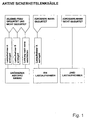
- Fig. 1
- zeigt schematisch Betriebsmodi von Verstelleinrichtungen eines ersten Ausführungsbeispiels einer Lenksäule,
- Fig. 2
- zeigen schematisch ein Schalt- und Aufbauschema der Steuerung des ersten Ausführungsbeispiels der Lenksäule von Fig. 1,
- Fig. 3a, 3b und 3c
- zeigen schematisch die Verstelleinrichtungen des ersten Ausführungsbeispiels der Lenksäule von Fig. 1 in einer Ansicht von unten (linke Hälfte von Fig. 3a) und oben (rechte Hälfte von Fig. 3a) bzw. entsprechende Querschnitte,
- Fig. 4
- zeigen schematisch die Antriebseinrichtungen des ersten Ausführungsbeispiels der Lenksäule von Fig. 1,
- Fig. 5
- zeigen schematisch die Lastaufnahmeeinrichtungen des ersten Ausführungsbeispiels der Lenksäule von Fig. 1, und
- Fig. 6
bis 8 - zeigen schematisch in einer Querschnittsansicht ein zweites Ausführungsbeispiel einer Lenksäule vor einer Auslösung, nach einer Auslösung bei einem kleinen Insassen bzw. nach einer Auslösung bei einem grossen.
- Fig. 1
- schematically shows operating modes of adjusting devices of a first exemplary embodiment of a steering column,
- Fig. 2
- schematically show a switching and construction diagram of the control of the first embodiment of the steering column of FIG. 1,
- 3a, 3b and 3c
- 1 schematically shows the adjusting devices of the first exemplary embodiment of the steering column from FIG. 1 in a view from below (left half of FIG. 3a) and above (right half of FIG. 3a) or corresponding cross sections,
- Fig. 4
- schematically show the drive devices of the first embodiment of the steering column of FIG. 1,
- Fig. 5
- schematically show the load suspension devices of the first embodiment of the steering column of Fig. 1, and
- 6 to 8
- schematically show in a cross-sectional view a second embodiment of a steering column before a release, after a release for a small occupant or after a release for a large one.
Gleiche Bezugszeichen in den einzelnen Figuren und Abbildungen der Zeichnungen bezeichnen gleiche oder ähnliche oder gleich oder ähnlich wirkende Komponenten. Anhand der Darstellungen in der Zeichnung werden auch solche Merkmale deutlich, die nicht mit Bezugszeichen versehen sind, unabhängig davon, ob solche Merkmale nachfolgend beschrieben sind oder nicht. Andererseits sind auch Merkmale, die in der vorliegenden Beschreibung enthalten, aber nicht in der Zeichnung sichtbar oder dargestellt sind, ohne weiteres für einen Fachmann verständlich.Identify the same reference numerals in the individual figures and illustrations of the drawings same or similar or identical or similar components. Based on the representations In the drawing, such features are also clear that are not identified by reference numerals are provided, regardless of whether such features are described below or not. On the other hand, features that are contained in the present description are also but are not visible or shown in the drawing, without further ado for a person skilled in the art understandable.
Unter Bezugnahme auf die Fig. 1, 2, 3a, 3b, 3c, 4 und 5, denen weitere Einzelheiten und Angaben zu entnehmen sind, werden nachfolgend weitere Merkmale, Funktionen und Vorteile der vorliegenden Erfindung anhand eines ersten Ausführungsbeispiels lediglich exemplarisch näher erläutert.Referring to Figs. 1, 2, 3a, 3b, 3c, 4 and 5, which further details and information can be seen, further features, functions and advantages are below of the present invention based on a first embodiment only as an example explained in more detail.
Dieses Ausführungsbeispiel betrifft eine aktive Sicherheitslenksäule für die drei wichtigsten
Beanspruchungen im Falle eines Unfalls, wie es durch das Schema der Fig. 1 verdeutlicht
wird, die den Aufbau und die Betriebsmodi für die entsprechende Lenksäule zeigt. Bei diesem
ersten Ausführungsbeispiel sind entsprechend drei Anforderungen bei einem Unfall drei auf
die jeweiligen Insassenparameter abgestimmte Betriebsmodi vorgesehen:
Bei dem ersten Ausführungsbeispiel ist somit eine zweifache parallel geschaltete Lastbegrenzung vorgesehen, die in Kombination bei nicht angeschnallten großen Personen die hohe Last abbaut. Bei nicht angeschnallten schweren Fahrern ist eine wesentlich größere Lastaufhahme notwendig, als es heutzutage in der Praxis üblich ist. Heutige aus der Praxis bekannte Sicherheitslenksäulen sind beispielsweise in einem "Schlitten" (siehe Fig. 1, 2, 3a, 3b, 3c und 4 sowie zugehörige Beschreibung) gelagert. Dieser "Schlitten" bewegt sich bei Überschreitung einer konstruktiv festgelegten Lastgrenze gegen ein sich verformendes Blech, wodurch gemäß der vorliegenden Erfindung die hohe Lastspitze bei schweren Fahrern mit beiden Lastaufnehmern A und B abgebaut wird.In the first exemplary embodiment there is therefore a double load limitation connected in parallel provided that in combination with tall people not wearing a seat belt the high load degrades. For heavy drivers who are not wearing a seat belt, there is a significantly higher load capacity necessary than is common in practice today. Today's safety steering columns known from practice are, for example, in a "carriage" (see Fig. 1, 2, 3a, 3b, 3c and 4 as well associated description) stored. This "slide" moves when one is exceeded structurally determined load limit against a deforming sheet, whereby according to the present invention, the high load peak in heavy drivers with both load cells A and B is broken down.
Bei angeschnallten großen Fahrern (erkennbar z.B. durch einen Schalter im Gurtschloß) wird bei einem Crash oder Unfall eine der beiden Lastbegrenzungen (z.B. der Lastaufnehmer A) außer Funktion gesetzt. Dies geschieht beispielsweise durch Entriegelung der Befestigung einer der Lastbegrenzungen durch einen Elektromagneten, einen pyrotechnisch entriegelbaren Bolzen o.ä.When the driver is buckled up (recognizable e.g. by a switch in the belt buckle) in the event of a crash or accident, one of the two load limits (e.g. load receiver A) disabled. This is done, for example, by unlocking the attachment of one the load limits by an electromagnet, a pyrotechnically unlockable Bolts or similar
Bei kleinen Fahrern (erkennbar z.B. durch einen Schalter in der Sitzschiene zur Lageabfrage) werden beide Lastaufhehmer A und B entriegelt und der Schlitten pyrotechnisch verfahren, um den nötigen Abstand zum explodierenden Airbag zu bekommen. Damit wird ein besonderer Vorteil der vorliegenden Erfindung erreicht.For small drivers (recognizable e.g. by a switch in the seat rail for position monitoring) both load sensors A and B are unlocked and the slide is pyrotechnically moved, to get the necessary distance to the exploding airbag. This makes it special Advantage of the present invention achieved.
Die Gewichtserkennung des großen Fahrers und die Positionserkennung z.B. einer kleinen Fahrerin können natürlich auch mittels elektronischer Gewichts- und Lagesensoren, die momentan vielerorts entwickelt werden, oder auf andere geeignete, dem Fachmann ohne weiteres bekannte oder zugängliche Arten ermittelt werden.The weight detection of the tall driver and the position detection e.g. a small one Drivers can of course also use electronic weight and position sensors, which are currently be developed in many places, or other suitable ones, to the person skilled in the art without further ado known or accessible species are identified.
Die Fig. 2 verdeutlicht schematisch das Schaltschema des ersten Ausführungsbeispiels.2 schematically illustrates the circuit diagram of the first embodiment.
Eine nur angedeutet dargestellte Lenksäule 1 für ein Fahrzeug (nicht gezeigt) hat einen üblichen
teleskopischen Aufbau, auf den wegen seiner Bekanntheit in zahlreichen Ausführungsformen
hier nicht weiter eingegangen wird, da sich die vorliegende Erfindung bei allen bekannten
Ausgestaltungen auch insgesamt rückziehbarer, nicht teleskopisch zusammenschiebbarer
Lenksäulen anwenden läßt und die vorliegende Erfindung nicht die eigentliche Bauart
solcher Lenksäulen betrifft. Die Lenksäule 1 hat einen Lenkrad-Endbereich 2 und ist mit Verstelleinrichtungen
3 versehen, die im Falle eines Unfalls auslösbar sind, um zumindest den
Lenkrad-Endbereich 2 der Lenksäule 1 von einem Insassen (nicht gezeigt) weg zu bewegen,
der auf einem Sitz 4 sitzt. Die Verstelleinrichtungen 3 sind für die drei in der Fig. verdeutlichten
Betriebsmodi ausgelegt. Eine Steuerung 5 erfaßt mittels Detektionseinrichtungen 6 Insassenparameter
und löst in Abhängigkeit von den Insassenparametern einen Betriebsmodus der
Verstelleinrichtungen 3 aus.A
Die Verstelleinrichtungen 3 enthalten Lastaufnahmeeinrichtungen 7 mit einem ersten und einem
zweiten Lastaufhehmer oder -begrenzer 8 (A) bzw. 9 (B), die jeweils einen eigenen Bolzen
10 bzw. 11 und ein gemeinsames Lastaufhahmeblech 12 enthalten, die Deformationseinrichtungen
(D) bilden. Durch die Bolzen 10 und 11 ist das Lastaufhahmeblech 12 mit einem
Schlitten 13 verbunden. Das Lastaufhahmeblech 12 ist mit einem Teleskopteil (nicht gezeigt)
der Lenksäule 1 fest verbunden, und der Schlitten 13 ist mit dem anderen Teleskopteil (nicht
gezeigt) der Lenksäule 1 fest verbunden. Wird das Teleskopteil (nicht gezeigt) der Lenksäule
1, das den Lenkrad-Endbereich 2 enthält, durch einen auf das Lenkrad (nicht bezeichnet) auftreffenden
Insassen (nicht dargestellt) belastet, so wird es in oder über das andere Teleskopteil
geschoben. Diese Bewegung wird durch die Lastaufnahmeeinrichtungen 7 gedämpft, da das
Lastaufhahmeblech 12 selbst und/oder gegen die Bolzen 10 und 11 verformt werden muß.The adjustment devices 3 contain load suspension devices 7 with a first and a
second load suspension device or limiter 8 (A) or 9 (B), each with its
Die Bolzen 10 und 11 verfügen jeweils über eine Sprengladung S, die von der Steuerung 5,
die beispielsweise verbunden ist mit oder integriert ist in einer Gesamtsteuerung (nicht
gezeigt) für einen Airbag, jeweils unabhängig voneinander elektrisch gezündet werden können,
um jeden der Bolzen 10 und 11 entsprechend unwirksam zu machen. An die Steuerung 5
sind als Detektionseinrichtungen 6 Zustandserkennungseinrichtungen 13 eines Gurtschlosses
14 in Form eines Gurt- oder Schloßnutzungsschalters 15 angeschlossen. Dieser Gurtnutzungsschalter
15 führt zu einem Gurtnutzungssignal, wenn der Insasse seinen Sicherheitsgurt (nicht
gezeigt) vorschriftsmäßig angelegt hat. Wird das Gurtnutzungssignal nicht erzeugt, so ist die
Steuerung darüber informiert, dass der Insasse nicht ordnungsgemäß angeschnallt ist.The
Weiterhin sind in den Detektionseinrichtungen 6 Positionserkennungseinrichtungen 16 enthalten,
die durch einen Positionsschalter 17 in einer Sitzschiene 18 des Sitzes 4 gebildet sind.
Dieser Positionsschalter 17 führt zu einem Nahpositionssignal, wenn der Sitz 4 die Position
des Positionsschalters 17 erreicht hat oder näher als der Positionsschalter 17 an der Lenksäule
1 ist. Dadurch erhält die Steuerung 5 die Information, dass es sich bei dem Insassen um eine
kleine Person handelt. Wird das Nahpositionssignal nicht erzeugt, so ist die Steuerung darüber
informiert, dass es sich bei dem Insassen um eine grosse Person handelt.Furthermore,
Durch die möglichen Kombinationen von Gurtnutzungssignal und Nahpositionssignal kann die Steuerung 5 jeden der drei Betriebsmodi der Verstelleinrichtungen 3 gemäß der Fig. 1 einstellen. Due to the possible combinations of belt usage signal and near position signal the controller 5 set each of the three operating modes of the adjusting devices 3 according to FIG. 1.
Hat die Steuerung 5 das Nahpositionssignal erhalten, so veranlaßt sie den Betriebsmodus für
eine angeschnallte oder nicht angeschnallte "kleine Frau". In diesem Modus zündet die Steuerung
5 die Sprengladungen S der beiden Bolzen 10 und 11, so dass diese wirkungslos werden
und das Lastaufnahmeblech 12 und der Schlitten 13 entkoppelt sind. Ferner zündet die Steuerung
5 einen pyrotechnischen Sprengsatz 19 eines Gasgenerators 20, und das von diesem erzeugte
Gas beaufschlagt einen Kolben 21 mit einer Kolbenstange 22, die an das den Lenkrad-Endbereich
2 enthaltende Teleskopteil (nicht dargestellt) der Lenksäule 1 fest so angebunden
ist, dass die beiden Teleskopteile (nicht dargestellt) der Lenksäule 5 zusammengezogen werden.
Die Teile 19 bis 22 sind Bestandteile der Verstelleinrichtungen 3 und bilden zusammen
Antriebseinrichtungen 23. Durch das Zusammenziehen oder Zurückziehen der Lenksäule 1
wird für die "kleine Frau", die relativ nahe am Lenkrad (nicht bezeichnet) sitzt, mehr Freiraum
geschaffen, so dass sie von einem sich bei einem Unfall aufblasenden Airbag (nicht dargestellt)
nicht oder zumindest nicht fest getroffen wird.If the controller 5 has received the near position signal, it initiates the operating mode for
a buckled or unbuckled "little woman". The controller fires in this mode
5 the explosive charges S of the two
Hat die Steuerung 5 das Nahpositionssignal nicht erhalten, überprüft sie, ob das Gurtnutzungssignal
gegeben ist. Liegt das Gurtnutzungssignal vor, so veranlaßt die Steuerung 5 den
Betriebsmodus für einen angeschnallten "grossen Mann". In diesem Modus zündet die Steuerung
5 die Sprengladung S nur des Bolzens 11, so dass nur dieser wirkungslos wird und das
Lastaufnahmeblech 12 und der Schlitten 13 noch durch den Bolzen 10 gekoppelt sind. Der
Lastaufhehmer 8 (A) ist damit wirksam, um Energie abzubauen, die beim Aufprall des angeschnallten
"grossen Mannes" auf das Lenkrad (nicht bezeichnet) auftritt. Die Antriebseinrichtungen
23 werden nicht ausgelöst.If the controller 5 has not received the near position signal, it checks whether the belt usage signal
given is. If the belt usage signal is present, the controller 5 initiates the
Operating mode for a buckled "big man". The controller fires in this mode
5 the explosive charge S only of the
Erhält die Steuerung 5 weder das Nahpositionssignal noch das Gurtnutzungssignal erhalten,
so veranlaßt die Steuerung 5 den Betriebsmodus für einen unangeschnallten "grossen Mann".
In diesem Modus zündet die Steuerung 5 keine Sprengladung S, so dass das Lastaufnahmeblech
12 und der Schlitten 13 durch beide Bolzen 10 und 11 gekoppelt sind. Der Lastaufhehmer
8 (A) und der Lastaufnehmer 9 (B) sind damit wirksam, um Energie abzubauen, die beim
Aufprall des unangeschnallten "grossen Mannes" auf das Lenkrad (nicht bezeichnet) auftritt.
Die Antriebseinrichtungen 23 werden nicht ausgelöst.If the controller 5 receives neither the near position signal nor the belt usage signal,
the controller 5 thus initiates the operating mode for an unbuckled "tall man".
In this mode, the controller 5 does not ignite an explosive charge S, so that the load-receiving
Signalleitungen zwischen der Steuerung 5 und den Sprengladungen S, dem pyrotechnischen
Sprengsatz 19 sowie den Detektionseinrichtungen 6 sind als Linien oder Striche in der Fig. 2
eingezeichnet. Signal lines between the controller 5 and the explosive charges S, the pyrotechnic
The
Die Fig. 3a, 3b und 3c zeigen einen Schlitten 13 zur Aufnahme der Lenkung (nicht gezeigt) in
seiner Schlittenaufhahme 24 in der Fig. 3a links von unten und rechts von oben und in den
Fig. 3b und 3c jeweils geschnitten. Der pyrotechnische Gasgenerator 20 der Antriebseinrichtungen
23 ist einerseits an der Schlittenaufnahme 24 und andererseits am Schlitten 13 befestigt.3a, 3b and 3c show a
Auf der rechten Seite der Fig. 3a sind der Lastaufnehmer 8 (A) und der Lastaufnehmer 9 (B)
einstückig in Einbaulage gezeigt. Die Lastaufhehmer 8 und 9 sind einerseits mit den Bolzen
10 bzw. 11 am Schlitten 13 und andererseits an der Schlittenaufnahme 24 mit Verschraubungen
25 versehen. Der verschiebbare Teleskopteil (nicht gezeigt) der Lenksäule 1 wird in der
Ausnehmung L fest montiert.The load receiver 8 (A) and the load receiver 9 (B) are on the right side of FIG. 3a.
shown in one piece in installation position. The
Die Antriebseinrichtungen 23 sind in der Fig. 4 gesondert dargestellt, wie sie bereits im Zusammenhang
mit der Fig. 2 erläutert wurden.The
Die Fig. 5 zeigt oben vor, d.h. in einem einbaufertigen Zustand, und unten nach einer Betätigung
beider Lastaufhehmer 8 und 9 das Lastaufnahmeblech 12, bei dem es sich um ein Stanzteil
handelt.Figure 5 shows above, i.e. in a ready-to-install condition, and below after actuation
both
Als weitere erfinderische Besonderheit ist der Lastbegrenzer 8 (A) derart gestaltet, daß er mittels
des Bolzens 10 sofort bei einer Lastüberschreitung an Reißlinien 26 einreißt. Dabei
schiebt sich das Ende des Lastbegrenzers 8 (A) zwangsläufig über den Lastbegrenzer 9 (B),
dessen Bolzen 11 sich vorerst in einem Schlitz 27 des Lastbegrenzers 9 (B) bewegt. Diese
Auslegung führt in vorteilhafter Weise dazu, daß sich die Ausreißkräfte der beiden Lastaufnehmer
8 (A) und 9 (B) addieren. Würden sie parallel nebeneinander einreißen, würde nur einer
der beiden Lastaufhehmer A oder B arbeiten.As a further inventive feature, the load limiter 8 (A) is designed such that it is by means of
of the
Durch die Erfindung wird somit gemäß des ersten Ausführungsbeispiels insbesondere eine Sicherheitslenksäule mit einem Crashschlitten geschaffen, der zwei Lastaufnehmer hat, für angeschnallte und nicht angeschnallte große und kleine Personen. Gemäß einer bevorzugten Weiterbildung dieser Ausführung erfolgt eine Steuerung mit einem Schloßnutzungsschalter. In weiterer Fortbildung der Erfindung wird der Crashschlitten für die kleine Personen als "Ab-. standsschlitten" genutzt und werden seine Lastaufnehmer außer Betrieb gesetzt. Eine Feststellung kleiner Personen kann bevorzugt über eine elektrische Sitzlageerkennung erfolgen. According to the first exemplary embodiment, the invention thus in particular makes a safety steering column created with a crash sled that has two load sensors for buckled and not buckled tall and small people. According to a preferred A further development of this embodiment is a control with a lock usage switch. In a further development of the invention, the crash slide for small people is called "Ab-. stationary sled "and its load sensors are taken out of operation Smaller people can preferably use an electrical seat position detection.
Besonders bevorzugt ist es gemäß der vorliegenden Erfindung, wenn die Lastaufhehmer derart hintereinander laufend gebaut sind, z.B. mittels eines Schlitzes in einer Anbindung, zum verzögerten Anlauf, daß sich die Lastaulhahmen bei der Last addieren.According to the present invention, it is particularly preferred if the load suspension devices are of this type are built in a row, e.g. by means of a slot in a connection to the delayed Start-up that the load frames add up with the load.
Lediglich der Vollständigkeit halber wird noch darauf hingewiesen, dass die beiden Teleskopteile,
wie z.B. ineinander gesteckte Rohre, der Lenksäule 1 im Normalbetrieb zwar einerseits
fixiert sind, so dass sie nicht ohne weiteres zusammengeschoben werden können, dass
aber diese Fixierung andererseits so schwach ist (z.B. Kunststoffbolzen), dass dadurch erstens
keine merkliche Lastaufnahme für einen grossen (unangeschnallten) Fahrer erreicht werden
kann, und zweitens der Rückzug der Lenksäule durch die Antriebseinrichtungen bei einem
kleinen (angeschnallten) Fahrer nicht spürbar behindert wird. Dies gilt für das bereits erläuterte
Ausführungsbeispiel ebenso, wie für das nachfolgend erläuterte zweite
Ausführungsbeispiel.For the sake of completeness, it is pointed out that the two telescopic parts,
such as. nested pipes, the
Unter Bezugnahme auf die Fig. 6 bis 8, denen weitere Einzelheiten und Angaben zu entnehmen sind, werden nachfolgend weitere Merkmale, Funktionen und Vorteile der vorliegenden Erfindung anhand eines zweitens Ausführungsbeispiels lediglich exemplarisch näher erläutert. Insbesondere betrifft dieses Ausführungsbeispiel eine Sicherheitslenksäule mit pyrotechnisch angetriebener Verkürzung bei kleinen Fahrern und Lastspitzenabbau bei großen Fahrern. Heutige Lenksäulen sind zum Teil als Ergänzung zu einem Airbag bereits mit einem Lastspitzenabbau für schwere Personen ausgerüstet. Die Praxis hat ferner gezeigt, daß kleine und zu dicht am Airbag positionierte Fahrer teilweise durch diesen zu Tode kommen. Das zweite Ausführungsbeispiel schafft ebenfalls eine Lösung zum Lastspitzenabbau bei großen Fahrern und im gleichen System eine Lenksäulenverkürzung bei kleinen Fahrern bei einem Unfall.6 to 8, from which further details and information can be found are further features, functions and advantages of the present Invention with reference to a second embodiment only exemplified. In particular, this embodiment relates to a safety steering column with pyrotechnic driven shortening for small drivers and peak load reduction for large drivers. today Steering columns are already partially supplemented to an airbag with a peak load reduction equipped for heavy persons. Practice has also shown that small and too dense Drivers positioned on the airbag may die to some extent as a result. The second embodiment also creates a solution for reducing peak loads for large drivers and in same system a shortening of the steering column for small drivers in the event of an accident.
Die Fig. 6 bis 8 zeigen ein Lenksäulenaussenrohr 28 und ein Lenksäuleninnenrohr 29, die die
Teleskopteile einer Lenksäule 1 darstellen, wobei das Lenksäuleninnenrohr 29 den Lenkrad-Endbereich
2 der Lenksäule 1 enthält. An dem Lenksäulenaussenrohr 28 ist ein Aussenrohr-Ringkolben
30 beispielsweise durch eine Verclinchverbindung 31 befestigt. Der Aussenrohr-Ringkolben
30 enthält eine pyrotechnische Patrone 32, die mit Steuerkabeln K mit der Steuerung
5 (vergleiche Fig. 2) verbunden ist. Mit dem Lenksäuleninnenrohr 29 ist ein Innenrohr-Ringkolben
33 fest durch ebenfalls eine Verclinchverbindung 34 verbunden. Dieser Innenrohr-Ringkolben
33 enthält beim zweiten Ausführungsbeispiel ein oder mehrere in Schlitzen
35 gelagerte, entsprechend geformte Schneidemesser 36 als Teile von Deformationseinrichtungen
6. Die Schneidemesser 36 sind derart auf einem "Kipppunkt" 37 gelagert, daß sie bei
Antrieb über den Innenrohr-Ringkolben 33 gezielt in die Wandung 38 des Lenksäulenaussenrohrs
28 der Lenksäule 1 einschneiden. Die Schneidtiefe 39 des Spanes 40 wird durch einen
entsprechend geformten Anschlag 41 bestimmt. Die Größe des Spanes 40 ist proportional der
gewünschten Lastaufnahme. Die Deformationseinrichtungen 6 bilden Lastaufnahmen 42.6 to 8 show a steering column
Der Aussenrohr-Ringkolben 30 und der Innenrohr-Ringkolben 33 bilden Antriebseinrichtungen
23, die ebenso wie die Lastaufnahmen 42 Bestandteile der Verstelleinrichtungen 3 der
Lenksäule 1 sind.The outer
Die Fig. 8 zeigt eine entsprechende Lastaufnahme 42 in Funktion. Die Lastaufnahme 428 shows a
Die Fig. 7 zeigt die Funktion bei kleinen Fahrern. Hier drückt die Ladung 43 der pyrotechnische
Patrone 32 den Innenrohr-Ringkolben 33 verbunden mit dem Lenksäuleninnenrohr 29
nach unten und damit von einem Insassen (nicht gezeigt) weg. Gleichzeitig verhindert ein
vom Druck beaufschlagter Steuerstift 44 das Kippen des Schneidemessers 36 in die Stellung
"Lastaufnahme", d.h. zur Spanabhebung in der Wandung 38 des Lenksäulenaussenrohrs 28
der Lenksäule 1.Fig. 7 shows the function with small drivers. Here the
Zusammenfassend läßt sich das in den Fig. 6 bis 8 verdeutlichte Ausführungsbeispiel der vorliegenden Erfindung folgendermaßen erläutern:In summary, the exemplary embodiment of the present illustrated in FIGS. 6 to 8 can be seen Explain the invention as follows:
Ineinander schiebbare Lenksäulenrohre sind mit "Ringkolben" versehen, die bei kleinen Fahrern mittels eines pyrotechnischen Druckaufbaues dazwischen die Lenksäule verkürzen und damit einen sich aufblasenden Airbag auf eine größere Distanz bringen. In einem der Ringkolben ist eine lastaufnehmende Mechanik eingebaut, die bei großen Fahrern anstelle der Lenksäulenverkürzung wirksam wird und bei kleinen Fahrern mittels pyrotechnischem Druck außer Funktion gesetzt wird. Der zweite Ringkolben ist mit einer Lastaufnahmemechanik versehen. Im gezeigten Beispiel handelt es sich um entsprechend geformte und gelagerte kippbare Messer. Es kann sich hier ebenso um Wellrohre, materialverformende Kugeln o.ä. handeln (in den Figuren nicht gezeigt). Grundsätzlich ist die Funktion des lastaufnehmenden Ringkolbens derart, daß er automatisch Last aufnimmt und abbaut, wenn das innere Lenksäulenrohr relativ zum äußeren bewegt wird. Im gezeigten Fall wird das Messer spanabhebend in das äußere Lenksäulenrohr gedrückt. Alternativ kann diese Lastaufnahme bei einer pyrotechnischen Zündung bei entsprechender Leistung "überspielt" werden, oder wird das "Messer" wie im Beispiel durch einen druckbeaufschlagten Steuerstift außer Funktion gekippt.Steering column tubes that can be pushed into each other are provided with "ring pistons", which are used by small drivers shorten the steering column by means of a pyrotechnic pressure build-up and to bring an inflating airbag a greater distance. In one of the ring pistons a load-bearing mechanism is built in, which is used by tall drivers instead of shortening the steering column is effective and for small drivers using pyrotechnic pressure Function is set. The second ring piston is equipped with a load suspension mechanism. In the example shown, these are appropriately shaped and stored tiltable Knife. It can also be corrugated pipes, material-deforming balls or similar. act (in the figures not shown). The function of the load-bearing ring piston is fundamentally such that it automatically picks up and breaks down load when the inner steering column tube is relative is moved to the outside. In the case shown, the knife is machined into the outside Steering column tube pressed. Alternatively, this load pick-up can be used with a pyrotechnic ignition with the appropriate performance "overplayed", or the "knife" as in the example tilted out of function by a pressurized control pin.
Bei der Lenksäule eines Automobiles ist das innere und äußere Lenksäulenrohr beispielsweise auf möglichst großen Durchmesserunterschied ausgelegt. Wie es heute u.a. üblich ist, wird das äußere Lenksäulenrohr in Lagern positioniert (in den Figuren nicht gezeigt). Das innere Lenksäulenrohr ist zum äußeren formschlüssig mit entsprechenden Ringkolben (Nuten/Form) verbunden. Das Ringkolbenpaar ist z.B. durch Verclinchen mit je einem äußeren und je einem inneren Rohr verbunden. Ein Ringkolben beinhaltet eine pyrotechnische Ladung, deren Druck die Ringkolben voneinander weg drücken und damit die Lenksäule verkürzen bzw. das Lenkrad in Fahrtrichtung nach vom vom Insassen weg ziehen kann.In the steering column of an automobile, for example, the inner and outer steering column tube designed for the largest possible difference in diameter. As it is today is common will the outer steering column tube is positioned in bearings (not shown in the figures). The inner Steering column tube is form-fitting to the outside with corresponding ring pistons (grooves / shape) connected. The pair of ring pistons is e.g. by linking with one outer and one each inner tube connected. An annular piston contains a pyrotechnic charge, the pressure of which press the ring pistons away from each other and thus shorten the steering column or the steering wheel can pull away from the occupant in the direction of travel.
Kleine Fahrer können auch bei dem zweiten Ausrührungsbeispiel festgestellt werden z.B. durch entsprechende elektronische Überwachungssysteme oder eine Sitzpositionserkennung mittels Schaltern in der Sitzschiene.Small drivers can also be found in the second embodiment example e.g. through appropriate electronic monitoring systems or seat position detection using switches in the seat rail.
Die vorstehenden und in den Zeichnungen wiedergegebenen Merkmale und Merkmalskombinationen des Ausrührungsbeispiels dienen lediglich der exemplarischen Verdeutlichung der Erfindung und nicht deren Beschränkung. Der Offenbarungsumfang der vorliegenden gesamten Unterlagen ist durch das bestimmt, was für den Fachmann ohne weiteres in den Ansprüchen, aber auch aus der Beschreibung, der Zeichnung und den vollständigen Inhalten der durch Bezugnahme aufgenommenen Voranmeldungen der vorliegenden Anmelderin entnehmbar ist. Insbesondere umfasst die Erfindung ferner alle Variationen, Modifikationen und Substitutionen, die der Fachmann dem gesamten Offenbarungsumfang der vorliegenden Unterlagen entnehmen kann. Insbesondere sind alle einzelnen Merkmale und Ausgestaltungsmöglichkeiten der Erfindung und ihrer Ausführungsbeispiele kombinierbar.The above features and combinations of features shown in the drawings of the execution example only serve to illustrate the example Invention and not limitation. The scope of disclosure of the present entire Documentation is determined by what is readily apparent to those skilled in the claims, but also from the description, the drawing and the complete content of the prior applications of the present applicant are incorporated by reference is. In particular, the invention further includes all variations, modifications and Substitutions that the specialist the entire scope of disclosure of the present documents can see. In particular, all individual features and design options are the invention and its embodiments can be combined.
Claims (41)
dadurch gekennzeichnet, dass die Lastaufnahmeeinrichtungen (7) Deformationseinrichtungen (6) enthalten, die mittels der Steuerung (5) in Abhängigkeit von den Insassenparametern zur Realisierung eines bestimmten Betriebsmodus der Verstelleinrichtungen (3) in oder ausser Wirkung bringbar sind, und
dass die Deformationseinrichtungen (6) wenigstens ein längs eines Bewegungsweges zur Lastaufnahme spanabhebendes Schneidmesser (36) enthalten, das durch Kippen wahlweise in eine Lastaufnahmestellung bringbar ist.Steering column for a vehicle, with adjusting devices (3) which can be triggered in the event of an accident, in order to move at least one steering wheel end region (2) of the steering column (1) away from an occupant, the adjusting devices (3) being load-bearing devices (7) for damping a movement of at least the steering wheel end region (2) of the steering column (1) away from an occupant and designed for at least two operating modes, and wherein a controller (5) for detecting occupant parameters by means of detection devices (6) and triggering an operating mode the adjustment devices (3) are provided as a function of the occupant parameters,
characterized in that the load suspension devices (7) contain deformation devices (6) which can be brought into or out of effect by means of the control (5) depending on the occupant parameters for realizing a specific operating mode of the adjusting devices (3), and
that the deformation devices (6) contain at least one cutting knife (36) cutting along a movement path for load-carrying, which can be brought into a load-carrying position by tilting.
dass die Antriebseinrichtungen (23) im Falle eines Unfalls von der Steuerung (5) in Abhängigkeit von den Insassenparametern auslösbar sind.Steering column according to one of the preceding claims, characterized in that the adjusting devices (3) contain drive devices (23) for causing the movement of at least the steering wheel end region (2) of the steering column (1) away from an occupant, and
that the drive devices (23) can be triggered in the event of an accident by the control (5) as a function of the occupant parameters.
dass die Lastaufnahmeeinrichtungen (7) im Falle eines Unfalls von der Steuerung (5) in Abhängigkeit von den Insassenparametern direkt oder indirekt betreibbar sind.Steering column according to one of the preceding claims, characterized in that the adjusting devices (3) contain load-receiving devices (7) for damping movement of at least the steering wheel end region (2) of the steering column (1) away from an occupant, and
that the load suspension devices (7) can be operated directly or indirectly by the control (5) in the event of an accident, depending on the occupant parameters.
dadurch gekennzeichnet, dass die Steuerung (5) zum Betreiben der Lastaufnahmeeinrichtungen (7) oder ggf. jeder Stufe (A, B) davon einzeln in Abhängigkeit vom Angurtzustand und/oder der Sitzposition des Insassen ausgelegt ist.Steering column according to claim 19 or 20 in connection with one of claims 9 to 16,
characterized in that the control (5) for operating the load suspension devices (7) or possibly each stage (A, B) thereof is designed individually depending on the state of the seat belt and / or the seating position of the occupant.
wobei im Falle eines Unfalls zumindest ein Lenkrad-Endbereich (2) der Lenksäule (1) mittels Verstelleinrichtungen (3) von einem Insassen weg bewegt wird,
wobei mittels Detektionseinrichtungen (6) Insassenparameter erfaßt werden, und
wobei die Bewegung zumindest des Lenkrad-Endbereiches (2) der Lenksäule (1) vom Insassen weg mittels einer Steuerung (5) in Abhängigkeit von den Insassenparametern gemäß einem Betriebsmodus von mehreren Betriebsmodi der Verstelleinrichtungen (3) erfolgt,
dadurch gekennzeichnet, dass zur Realisierung eines bestimmten Betriebsmodus der Verstelleinrichtungen (3) mittels der Steuerung (5) in Abhängigkeit von den Insassenparametern Deformationseinrichtungen (6) zur bewegungsdämpfenden Lastaufnahme in oder ausser Wirkung gebracht werden, und
dass, wenn die Deformationseinrichtungen wirksam sind, im Falle eines Unfalls wenigstens spanabhebendes Schneidmesser (36) der Deformationseinrichtungen (6) zur bewegungsdämpfenden Lastaufnahme längs eines Bewegungsweges durch Kippen in eine Lastaufnahmestellung verstellt wird.Adjustment method for a steering column (1) of a vehicle,
in the event of an accident, at least one end of the steering wheel (2) of the steering column (1) is moved away from an occupant by means of adjusting devices (3),
occupant parameters are detected by means of detection devices (6), and
the movement of at least the steering wheel end region (2) of the steering column (1) away from the occupant by means of a controller (5) as a function of the occupant parameters in accordance with an operating mode of several operating modes of the adjusting devices (3),
characterized in that, in order to implement a specific operating mode of the adjusting devices (3) by means of the control (5), depending on the occupant parameters, deformation devices (6) for movement-damping load absorption are brought into or out of action, and
that if the deformation devices are effective, in the event of an accident, at least cutting cutting knife (36) of the deformation devices (6) for movement-damping load suspension along a movement path is adjusted by tilting into a load suspension position.
Applications Claiming Priority (5)
| Application Number | Priority Date | Filing Date | Title |
|---|---|---|---|
| DE29910056U | 1999-06-09 | ||
| DE29910058U | 1999-06-09 | ||
| DE29910056 | 1999-06-09 | ||
| DE29910058 | 1999-06-09 | ||
| EP00945629A EP1187752B1 (en) | 1999-06-09 | 2000-06-09 | Steering column and method for moving a steering column |
Related Parent Applications (1)
| Application Number | Title | Priority Date | Filing Date |
|---|---|---|---|
| EP00945629.4 Division | 2000-06-09 |
Publications (3)
| Publication Number | Publication Date |
|---|---|
| EP1384643A2 true EP1384643A2 (en) | 2004-01-28 |
| EP1384643A3 EP1384643A3 (en) | 2004-02-04 |
| EP1384643B1 EP1384643B1 (en) | 2005-08-31 |
Family
ID=26062564
Family Applications (3)
| Application Number | Title | Priority Date | Filing Date |
|---|---|---|---|
| EP03017865A Expired - Lifetime EP1384643B1 (en) | 1999-06-09 | 2000-06-09 | Steering column and method for adjusting a steering column |
| EP00945629A Expired - Lifetime EP1187752B1 (en) | 1999-06-09 | 2000-06-09 | Steering column and method for moving a steering column |
| EP04021210.2A Expired - Lifetime EP1510435B1 (en) | 1999-06-09 | 2000-06-09 | Steering column and adjustment procedure for a steering column |
Family Applications After (2)
| Application Number | Title | Priority Date | Filing Date |
|---|---|---|---|
| EP00945629A Expired - Lifetime EP1187752B1 (en) | 1999-06-09 | 2000-06-09 | Steering column and method for moving a steering column |
| EP04021210.2A Expired - Lifetime EP1510435B1 (en) | 1999-06-09 | 2000-06-09 | Steering column and adjustment procedure for a steering column |
Country Status (5)
| Country | Link |
|---|---|
| EP (3) | EP1384643B1 (en) |
| AU (1) | AU5964500A (en) |
| DE (2) | DE50007693D1 (en) |
| ES (3) | ES2440465T3 (en) |
| WO (1) | WO2000076832A1 (en) |
Families Citing this family (5)
| Publication number | Priority date | Publication date | Assignee | Title |
|---|---|---|---|---|
| US6581966B2 (en) * | 2001-01-05 | 2003-06-24 | Ford Global Technologies, Inc. | Twin axis steering wheel system |
| ES2280642T3 (en) * | 2002-05-07 | 2007-09-16 | Thyssenkrupp Presta Ag | SECURITY MANAGEMENT SYSTEM AND OPERATING PROCEDURE OF THE SAME. |
| DE102009009577B3 (en) * | 2009-02-19 | 2010-05-27 | Thyssenkrupp Presta Ag | Steering column for a motor vehicle |
| DE102012100626B3 (en) | 2012-01-25 | 2013-02-21 | Thyssenkrupp Presta Aktiengesellschaft | Steering column for a motor vehicle |
| DE102012111890B3 (en) | 2012-12-06 | 2013-12-24 | Thyssenkrupp Presta Aktiengesellschaft | Steering column for a motor vehicle |
Citations (3)
| Publication number | Priority date | Publication date | Assignee | Title |
|---|---|---|---|---|
| WO1998022325A1 (en) | 1996-11-21 | 1998-05-28 | Ab Volvo | Device and method for occupant protection in vehicles |
| WO1998058831A1 (en) | 1997-06-23 | 1998-12-30 | Volvo Personvagnar Ab | Impact-absorbing device for protection of passengers in a vehicle |
| DE19829237A1 (en) | 1997-06-30 | 1999-01-07 | Volkswagen Ag | Steering wheel and column displaceable in crash |
Family Cites Families (3)
| Publication number | Priority date | Publication date | Assignee | Title |
|---|---|---|---|---|
| NL7502142A (en) * | 1975-02-21 | 1976-08-24 | Noord Nederlandsche Maschf | Impact-absorbing device for rail vehicle - has telescopic elements of which one cuts into the other on impact |
| JP2776102B2 (en) * | 1991-12-11 | 1998-07-16 | 日産自動車株式会社 | Vehicle safety devices |
| DE59914786D1 (en) * | 1998-05-11 | 2008-07-24 | Thyssenkrupp Presta Ag | SAFETY COLUMN, SAFETY SYSTEM FOR A VEHICLE AND VEHICLE WITH A SAFETY SYSTEM AND SAFETY PROCEDURE |
-
2000
- 2000-06-09 ES ES04021210.2T patent/ES2440465T3/en not_active Expired - Lifetime
- 2000-06-09 WO PCT/DE2000/001889 patent/WO2000076832A1/en not_active Ceased
- 2000-06-09 ES ES03017865T patent/ES2248691T3/en not_active Expired - Lifetime
- 2000-06-09 DE DE50007693T patent/DE50007693D1/en not_active Expired - Lifetime
- 2000-06-09 ES ES00945629T patent/ES2226874T3/en not_active Expired - Lifetime
- 2000-06-09 EP EP03017865A patent/EP1384643B1/en not_active Expired - Lifetime
- 2000-06-09 EP EP00945629A patent/EP1187752B1/en not_active Expired - Lifetime
- 2000-06-09 AU AU59645/00A patent/AU5964500A/en not_active Abandoned
- 2000-06-09 DE DE50011087T patent/DE50011087D1/en not_active Expired - Lifetime
- 2000-06-09 EP EP04021210.2A patent/EP1510435B1/en not_active Expired - Lifetime
Patent Citations (3)
| Publication number | Priority date | Publication date | Assignee | Title |
|---|---|---|---|---|
| WO1998022325A1 (en) | 1996-11-21 | 1998-05-28 | Ab Volvo | Device and method for occupant protection in vehicles |
| WO1998058831A1 (en) | 1997-06-23 | 1998-12-30 | Volvo Personvagnar Ab | Impact-absorbing device for protection of passengers in a vehicle |
| DE19829237A1 (en) | 1997-06-30 | 1999-01-07 | Volkswagen Ag | Steering wheel and column displaceable in crash |
Also Published As
| Publication number | Publication date |
|---|---|
| EP1510435B1 (en) | 2013-09-25 |
| ES2440465T3 (en) | 2014-01-29 |
| EP1187752A1 (en) | 2002-03-20 |
| AU5964500A (en) | 2001-01-02 |
| WO2000076832A8 (en) | 2001-04-19 |
| EP1510435A2 (en) | 2005-03-02 |
| EP1510435A3 (en) | 2009-09-30 |
| EP1384643B1 (en) | 2005-08-31 |
| EP1384643A3 (en) | 2004-02-04 |
| WO2000076832A1 (en) | 2000-12-21 |
| ES2226874T3 (en) | 2005-04-01 |
| ES2248691T3 (en) | 2006-03-16 |
| DE50011087D1 (en) | 2005-10-06 |
| EP1187752B1 (en) | 2004-09-08 |
| DE50007693D1 (en) | 2004-10-14 |
Similar Documents
| Publication | Publication Date | Title |
|---|---|---|
| DE19938938B4 (en) | The vehicle occupant protection system | |
| DE69409664T2 (en) | VEHICLE SEAT | |
| DE19847385C1 (en) | Motor vehicle fender arrangement has shape memory spring arrangement that can be transferred into special configuration by activation unit in which it forces fender into rest position | |
| EP0691910B1 (en) | Safety device for vehicles | |
| DE19931804A1 (en) | Protective device for vehicle occupant, which can move seat back in turning motion relative to seat and block this movement | |
| DE2338026C3 (en) | Impact protection device for the driver of a motor vehicle | |
| EP1016567A2 (en) | Vehicle safety device protecting the occupant's feet | |
| DE102010062550A1 (en) | Occupant safety system | |
| WO2000069708A1 (en) | Front hood assembly | |
| WO2019180213A1 (en) | Vehicle seat arrangement | |
| DE102008043617A1 (en) | vehicle seat | |
| EP2096007A1 (en) | Pedestrian protection device at the front bonnet of a motor vehicle | |
| EP1077863B1 (en) | Safety steering column, safety system for a vehicle, vehicle equipped with a safety system and safety method | |
| DE4414432A1 (en) | Vehicle with integral crumple zone | |
| DE60025984T2 (en) | Device for the protection of the occupants | |
| DE10261870A1 (en) | Motor car pedestrian protection system has a control unit, sensors and device for lowering the bonnet or a raised part of the bonnet to protect driver and passenger in an accident subsequent to the initial pedestrian impact | |
| DE602004008322T2 (en) | SECURITY ARRANGEMENT | |
| EP1187752B1 (en) | Steering column and method for moving a steering column | |
| DE69700078T2 (en) | Active control of the occupant's body with a restraint system with limited traction during a frontal impact | |
| DE102005021725B4 (en) | vehicle | |
| EP1369297B1 (en) | Vehicle and method for reducing the impact on a vehicle occupant during collision | |
| DE10020660A1 (en) | Vehicle with crash-active front structure has large-surface soft nose | |
| EP1202897B1 (en) | Steering column and method of adjusting a steering column | |
| DE19820214B4 (en) | Motor vehicle with a driver's seat | |
| DE10061043A1 (en) | Impact resistance actuator for motor vehicle seat drives seat in reverse direction to impact induced movement |
Legal Events
| Date | Code | Title | Description |
|---|---|---|---|
| PUAI | Public reference made under article 153(3) epc to a published international application that has entered the european phase |
Free format text: ORIGINAL CODE: 0009012 |
|
| PUAL | Search report despatched |
Free format text: ORIGINAL CODE: 0009013 |
|
| AC | Divisional application: reference to earlier application |
Ref document number: 1187752 Country of ref document: EP Kind code of ref document: P |
|
| AK | Designated contracting states |
Kind code of ref document: A2 Designated state(s): DE ES FR GB IT |
|
| AK | Designated contracting states |
Kind code of ref document: A3 Designated state(s): DE ES FR GB IT |
|
| 17P | Request for examination filed |
Effective date: 20040329 |
|
| AKX | Designation fees paid |
Designated state(s): DE ES FR GB IT |
|
| GRAP | Despatch of communication of intention to grant a patent |
Free format text: ORIGINAL CODE: EPIDOSNIGR1 |
|
| GRAS | Grant fee paid |
Free format text: ORIGINAL CODE: EPIDOSNIGR3 |
|
| GRAA | (expected) grant |
Free format text: ORIGINAL CODE: 0009210 |
|
| AC | Divisional application: reference to earlier application |
Ref document number: 1187752 Country of ref document: EP Kind code of ref document: P |
|
| AK | Designated contracting states |
Kind code of ref document: B1 Designated state(s): DE ES FR GB IT |
|
| REG | Reference to a national code |
Ref country code: GB Ref legal event code: FG4D Free format text: NOT ENGLISH |
|
| GBT | Gb: translation of ep patent filed (gb section 77(6)(a)/1977) |
Effective date: 20050831 |
|
| REF | Corresponds to: |
Ref document number: 50011087 Country of ref document: DE Date of ref document: 20051006 Kind code of ref document: P |
|
| REG | Reference to a national code |
Ref country code: ES Ref legal event code: FG2A Ref document number: 2248691 Country of ref document: ES Kind code of ref document: T3 |
|
| ET | Fr: translation filed | ||
| PLBE | No opposition filed within time limit |
Free format text: ORIGINAL CODE: 0009261 |
|
| STAA | Information on the status of an ep patent application or granted ep patent |
Free format text: STATUS: NO OPPOSITION FILED WITHIN TIME LIMIT |
|
| 26N | No opposition filed |
Effective date: 20060601 |
|
| PGFP | Annual fee paid to national office [announced via postgrant information from national office to epo] |
Ref country code: DE Payment date: 20140829 Year of fee payment: 15 |
|
| PGFP | Annual fee paid to national office [announced via postgrant information from national office to epo] |
Ref country code: ES Payment date: 20141120 Year of fee payment: 15 Ref country code: GB Payment date: 20141120 Year of fee payment: 15 |
|
| PGFP | Annual fee paid to national office [announced via postgrant information from national office to epo] |
Ref country code: FR Payment date: 20141118 Year of fee payment: 15 |
|
| PGFP | Annual fee paid to national office [announced via postgrant information from national office to epo] |
Ref country code: IT Payment date: 20141125 Year of fee payment: 15 |
|
| REG | Reference to a national code |
Ref country code: DE Ref legal event code: R119 Ref document number: 50011087 Country of ref document: DE |
|
| PG25 | Lapsed in a contracting state [announced via postgrant information from national office to epo] |
Ref country code: IT Free format text: LAPSE BECAUSE OF NON-PAYMENT OF DUE FEES Effective date: 20150609 |
|
| GBPC | Gb: european patent ceased through non-payment of renewal fee |
Effective date: 20150609 |
|
| REG | Reference to a national code |
Ref country code: FR Ref legal event code: ST Effective date: 20160229 |
|
| PG25 | Lapsed in a contracting state [announced via postgrant information from national office to epo] |
Ref country code: DE Free format text: LAPSE BECAUSE OF NON-PAYMENT OF DUE FEES Effective date: 20160101 Ref country code: GB Free format text: LAPSE BECAUSE OF NON-PAYMENT OF DUE FEES Effective date: 20150609 |
|
| PG25 | Lapsed in a contracting state [announced via postgrant information from national office to epo] |
Ref country code: FR Free format text: LAPSE BECAUSE OF NON-PAYMENT OF DUE FEES Effective date: 20150630 |
|
| REG | Reference to a national code |
Ref country code: ES Ref legal event code: FD2A Effective date: 20160729 |
|
| PG25 | Lapsed in a contracting state [announced via postgrant information from national office to epo] |
Ref country code: ES Free format text: LAPSE BECAUSE OF NON-PAYMENT OF DUE FEES Effective date: 20150610 |