EP1384887A2 - Compresseur à déplacement alternatif - Google Patents
Compresseur à déplacement alternatif Download PDFInfo
- Publication number
- EP1384887A2 EP1384887A2 EP03024463A EP03024463A EP1384887A2 EP 1384887 A2 EP1384887 A2 EP 1384887A2 EP 03024463 A EP03024463 A EP 03024463A EP 03024463 A EP03024463 A EP 03024463A EP 1384887 A2 EP1384887 A2 EP 1384887A2
- Authority
- EP
- European Patent Office
- Prior art keywords
- coating layer
- piston
- shoe
- cam
- tin
- Prior art date
- Legal status (The legal status is an assumption and is not a legal conclusion. Google has not performed a legal analysis and makes no representation as to the accuracy of the status listed.)
- Granted
Links
Images



Classifications
-
- F—MECHANICAL ENGINEERING; LIGHTING; HEATING; WEAPONS; BLASTING
- F04—POSITIVE - DISPLACEMENT MACHINES FOR LIQUIDS; PUMPS FOR LIQUIDS OR ELASTIC FLUIDS
- F04B—POSITIVE-DISPLACEMENT MACHINES FOR LIQUIDS; PUMPS
- F04B27/00—Multi-cylinder pumps specially adapted for elastic fluids and characterised by number or arrangement of cylinders
- F04B27/08—Multi-cylinder pumps specially adapted for elastic fluids and characterised by number or arrangement of cylinders having cylinders coaxial with, or parallel or inclined to, main shaft axis
- F04B27/0873—Component parts, e.g. sealings; Manufacturing or assembly thereof
- F04B27/0878—Pistons
-
- F—MECHANICAL ENGINEERING; LIGHTING; HEATING; WEAPONS; BLASTING
- F04—POSITIVE - DISPLACEMENT MACHINES FOR LIQUIDS; PUMPS FOR LIQUIDS OR ELASTIC FLUIDS
- F04B—POSITIVE-DISPLACEMENT MACHINES FOR LIQUIDS; PUMPS
- F04B27/00—Multi-cylinder pumps specially adapted for elastic fluids and characterised by number or arrangement of cylinders
- F04B27/08—Multi-cylinder pumps specially adapted for elastic fluids and characterised by number or arrangement of cylinders having cylinders coaxial with, or parallel or inclined to, main shaft axis
- F04B27/0873—Component parts, e.g. sealings; Manufacturing or assembly thereof
- F04B27/0878—Pistons
- F04B27/0886—Piston shoes
-
- F—MECHANICAL ENGINEERING; LIGHTING; HEATING; WEAPONS; BLASTING
- F05—INDEXING SCHEMES RELATING TO ENGINES OR PUMPS IN VARIOUS SUBCLASSES OF CLASSES F01-F04
- F05C—INDEXING SCHEME RELATING TO MATERIALS, MATERIAL PROPERTIES OR MATERIAL CHARACTERISTICS FOR MACHINES, ENGINES OR PUMPS OTHER THAN NON-POSITIVE-DISPLACEMENT MACHINES OR ENGINES
- F05C2201/00—Metals
- F05C2201/02—Light metals
- F05C2201/021—Aluminium
-
- F—MECHANICAL ENGINEERING; LIGHTING; HEATING; WEAPONS; BLASTING
- F05—INDEXING SCHEMES RELATING TO ENGINES OR PUMPS IN VARIOUS SUBCLASSES OF CLASSES F01-F04
- F05C—INDEXING SCHEME RELATING TO MATERIALS, MATERIAL PROPERTIES OR MATERIAL CHARACTERISTICS FOR MACHINES, ENGINES OR PUMPS OTHER THAN NON-POSITIVE-DISPLACEMENT MACHINES OR ENGINES
- F05C2201/00—Metals
- F05C2201/02—Light metals
- F05C2201/025—Boron
-
- F—MECHANICAL ENGINEERING; LIGHTING; HEATING; WEAPONS; BLASTING
- F05—INDEXING SCHEMES RELATING TO ENGINES OR PUMPS IN VARIOUS SUBCLASSES OF CLASSES F01-F04
- F05C—INDEXING SCHEME RELATING TO MATERIALS, MATERIAL PROPERTIES OR MATERIAL CHARACTERISTICS FOR MACHINES, ENGINES OR PUMPS OTHER THAN NON-POSITIVE-DISPLACEMENT MACHINES OR ENGINES
- F05C2201/00—Metals
- F05C2201/04—Heavy metals
- F05C2201/0433—Iron group; Ferrous alloys, e.g. steel
-
- F—MECHANICAL ENGINEERING; LIGHTING; HEATING; WEAPONS; BLASTING
- F05—INDEXING SCHEMES RELATING TO ENGINES OR PUMPS IN VARIOUS SUBCLASSES OF CLASSES F01-F04
- F05C—INDEXING SCHEME RELATING TO MATERIALS, MATERIAL PROPERTIES OR MATERIAL CHARACTERISTICS FOR MACHINES, ENGINES OR PUMPS OTHER THAN NON-POSITIVE-DISPLACEMENT MACHINES OR ENGINES
- F05C2201/00—Metals
- F05C2201/04—Heavy metals
- F05C2201/0433—Iron group; Ferrous alloys, e.g. steel
- F05C2201/0466—Nickel
-
- F—MECHANICAL ENGINEERING; LIGHTING; HEATING; WEAPONS; BLASTING
- F05—INDEXING SCHEMES RELATING TO ENGINES OR PUMPS IN VARIOUS SUBCLASSES OF CLASSES F01-F04
- F05C—INDEXING SCHEME RELATING TO MATERIALS, MATERIAL PROPERTIES OR MATERIAL CHARACTERISTICS FOR MACHINES, ENGINES OR PUMPS OTHER THAN NON-POSITIVE-DISPLACEMENT MACHINES OR ENGINES
- F05C2201/00—Metals
- F05C2201/04—Heavy metals
- F05C2201/0469—Other heavy metals
- F05C2201/0475—Copper or alloys thereof
-
- F—MECHANICAL ENGINEERING; LIGHTING; HEATING; WEAPONS; BLASTING
- F05—INDEXING SCHEMES RELATING TO ENGINES OR PUMPS IN VARIOUS SUBCLASSES OF CLASSES F01-F04
- F05C—INDEXING SCHEME RELATING TO MATERIALS, MATERIAL PROPERTIES OR MATERIAL CHARACTERISTICS FOR MACHINES, ENGINES OR PUMPS OTHER THAN NON-POSITIVE-DISPLACEMENT MACHINES OR ENGINES
- F05C2201/00—Metals
- F05C2201/04—Heavy metals
- F05C2201/0469—Other heavy metals
- F05C2201/049—Lead
-
- F—MECHANICAL ENGINEERING; LIGHTING; HEATING; WEAPONS; BLASTING
- F05—INDEXING SCHEMES RELATING TO ENGINES OR PUMPS IN VARIOUS SUBCLASSES OF CLASSES F01-F04
- F05C—INDEXING SCHEME RELATING TO MATERIALS, MATERIAL PROPERTIES OR MATERIAL CHARACTERISTICS FOR MACHINES, ENGINES OR PUMPS OTHER THAN NON-POSITIVE-DISPLACEMENT MACHINES OR ENGINES
- F05C2201/00—Metals
- F05C2201/04—Heavy metals
- F05C2201/0469—Other heavy metals
- F05C2201/0493—Tin
-
- F—MECHANICAL ENGINEERING; LIGHTING; HEATING; WEAPONS; BLASTING
- F05—INDEXING SCHEMES RELATING TO ENGINES OR PUMPS IN VARIOUS SUBCLASSES OF CLASSES F01-F04
- F05C—INDEXING SCHEME RELATING TO MATERIALS, MATERIAL PROPERTIES OR MATERIAL CHARACTERISTICS FOR MACHINES, ENGINES OR PUMPS OTHER THAN NON-POSITIVE-DISPLACEMENT MACHINES OR ENGINES
- F05C2201/00—Metals
- F05C2201/04—Heavy metals
- F05C2201/0469—Other heavy metals
- F05C2201/0496—Zinc
-
- F—MECHANICAL ENGINEERING; LIGHTING; HEATING; WEAPONS; BLASTING
- F05—INDEXING SCHEMES RELATING TO ENGINES OR PUMPS IN VARIOUS SUBCLASSES OF CLASSES F01-F04
- F05C—INDEXING SCHEME RELATING TO MATERIALS, MATERIAL PROPERTIES OR MATERIAL CHARACTERISTICS FOR MACHINES, ENGINES OR PUMPS OTHER THAN NON-POSITIVE-DISPLACEMENT MACHINES OR ENGINES
- F05C2253/00—Other material characteristics; Treatment of material
- F05C2253/12—Coating
Definitions
- the present invention relates generally to a compressor according to the preamble of claim 1.
- a reciprocating compressor for example, as shown in Figure 10, is typically employed in air conditioners for automobiles and the like.
- This compressor has a pair of cylinder blocks 30 and 31 combined with each other.
- a swash plate chamber 32 is defined between these cylinder blocks 30 and 31.
- Housings 35 and 36 are attached to the outer end faces of the cylinder blocks 30 and 31 via valve plates 33 and 34, respectively.
- An intake chamber 36 and a discharge chamber 37 are defined between the valve plate 33 and the housing 35 and also between the valve plate 34 and the housing 36.
- the drive shaft 39 is rotatably supported in these cylinder blocks 30 and 31.
- a swash plate 40 serving as a cam is fixed, in the swash plate chamber 32, to the drive shaft 39.
- a plural pairs of cylinder bores 41 and 42 are defined in the cylinder blocks 30 and 31 around the drive shaft 39.
- a double-headed piston 43 is housed in each pair of cylinder bores 41 and 42.
- Shoes 44 which serve as cam followers, are located between the swash plate 40 and each piston 43.
- Each shoe 44 has a sliding surface 45 that makes sliding contact with the front face or rear face of the swash plate 40 and a spherical surface 47 that makes sliding contact with a receiving recess 46 of the piston 43.
- each piston 43 is reciprocated in the cylinder bores 41, 42 via the shoes 44 under the action of the swash plate 40.
- a refrigerant gas is introduced from the intake chamber 37 to the cylinder bores 41 and 42 as each piston 43 moves from the top dead center to the bottom dead center.
- the refrigerant gas introduced into the cylinder bores 41 and 42 is compressed as the piston 43 moves from the bottom dead center to the top dead center and is discharged to the discharge chamber 38.
- the size of the cylinder bores 41 and 42 and increasing the sizes of the pistons 43, swash plate 40 and shoes 44 is contemplated.
- the pistons 43 and the swash plate 40 are generally made of a light aluminum alloy or the like. However, these members, which are made of the same metallic material, may seize. Accordingly, shoes 44 made of a ferrous metal are located between the pistons 43 and the swash plate 40 to prevent seizure between the pistons 43 and the swash plate 40. However, since ferrous metals have high specific gravity, the increase in the size of the shoes 44 increases the total weight of the compressor.
- a refrigerant gas is introduced from an external refrigerant circuit via the swash plate chamber 32 into the intake chamber 37.
- the refrigerant gas introduced into the swash plate chamber 32 cools each part in the swash plate chamber 32 and also prevents pulsation caused by the introduction of the refrigerant into the cylinder bores 41 and 42.
- R134a CF3CH2F
- Chlorine is used as an extreme-pressure additive.
- An "extreme-pressure additive” is a substance that reacts with the surface of a metal and forms a metallic compound film to reduce frictional resistance.
- the refrigerant gas introduced into the swash plate chamber 32 washes off, by its own action, lubricant located on the surfaces of the swash plate 40 and other parts, so that lubrication between the shoes 44 and the pistons 43 and swash plate 40 is not easily achieved.
- chlorine serving as the extreme-pressure additive, is not present in the refrigerant gas molecules, a great sliding resistance exists.
- the compressor according to the present invention has cylinder blocks containing cylinder bores.
- a drive shaft is rotatably supported in the cylinder blocks.
- a cam is attached to the drive shaft to be rotatable integrally therewith.
- a piston is slidably housed in the cylinder bores.
- a cam follower is slidably held between the piston and the cam. As the cam rotates, the piston is reciprocated via the cam follower.
- the piston is made of an aluminum or aluminum alloy matrix.
- the piston contains a receiving portion for slidably receiving the cam follower therein.
- a coating layer containing tin as a major component is formed at the receiving portion of the piston.
- the coating layers formed at the receiving portions of the pistons reduce sliding resistance between the receiving portions of the pistons and the cam followers. Accordingly, even if a shortage of a lubricant occurs in the compressor, the cam followers can slide smoothly in the receiving portions of the pistons. Thus, the cam can move the cam followers with a small force. Consequently, the load acting between the cam followers and the cam can be reduced to decrease sliding resistance between them.
- the compressor comprises: a cylinder block containing a cylinder bore; a drive shaft rotatably supported in the cylinder block; a cam attached to the drive shaft to be rotatable integrally therewith; a piston slidably housed in the cylinder bore; and a cam follower slidably interposed between the piston and the cam; the piston being reciprocated via the cam follower as the cam is rotated; the piston being made of an aluminum or aluminum alloy matrix and having a receiving portion for slidably receiving the cam follower therein, with a coating layer containing tin as a major component being formed at the receiving portion of t he piston.
- the cam follower may made of a ferrous metal matrix and have a first sliding portion slidably retained in the piston and a second sliding portion to be brought into slide contact with the cam; at least one of the first sliding portion and the second sliding portion having a coating layer containing tin as a major component.
- the compressor may comprise a piston having an outer circumference to be brought into slide contact with the inner circumference of the cylinder bore and the coating layer is also formed on the outer circumference of the piston.
- the cam may have a sliding portion to be brought into slide contact with the cam follower, with a coating layer containing tin as a major component being formed at the sliding portion.
- the cam further may have to be brought into slide contact with the second sliding portion of the cam follower, with a coating layer containing tin as a major component being formed at the sliding portion.
- the mentioned coating layer may contain at least one metal selected from the group consisting of copper, nickel, zinc, lead and indium.
- the cam follower may be a shoe having a spherical surface and the receiving portion of the piston is a recess which slidably receives the spherical surface of the shoe therein.
- the coating layer may contain one kind of solid lubricant selected from the group consisting of a fluororesin powder, a molybdenum disulfide powder, a carbon powder and a boron nitride powder.
- a swash plate type compressor according to a first embodiment of the present invention will be described below referring to Figure 1 to Figure 4.
- the mechanical construction of the compressor of the first embodiment is substantially the same as that of the compressor shown in Figure 10, which was described with reference to the prior art. Therefore, like or the same components as those in the compressor shown in Figure 10 are affixed with the same reference numbers, respectively, and a description of them will be omitted. Therefore, only differences from the compressor shown in Figure 10 will be described.
- each piston 1 has a coating layer 6 containing tin as a major component formed over its entire surface.
- Each piston 1 has a pair of receiving recesses 2 which slidably receive spherical surfaces of shoes 44.
- the piston 1 consists of a main body 5 made of an aluminum or aluminum alloy matrix and a coating layer 6 formed over the entire surface of the main body 5.
- the aluminum alloy for example, an Al-Si alloy or an Al-Si-Cu alloy can be suitably employed.
- the main body 5 is preferably an aluminum alloy matrix containing hard particles.
- Such aluminum alloy is typified by an aluminum-high silicon alloy.
- the aluminum-high silicon alloy contains about 10 to 30 % by weight of silicon. If the aluminum-high silicon alloy has a silicon content not exceeding the level at which a eutectic mixture is formed, the silicon can be present in the form of eutectic silicon (i.e., the hard particles).
- the main body 5 of the piston 1 is made of a matrix of aluminum-high silicon alloy 4 containing 12 % by weight of silicon 3.
- materials containing hard particles include, an Al-Mn intermetallic compound, an Al-Si-Mn intermetallic compound, an Al-Fe-Mn intermetallic compound and an Al-Cr intermetallic compound, and these materials may be used as the matrix of the main body 5.
- the shoes 44 are made of SUJ2 material (a steel material for a high carbon content chromium bearing) specified by JIS, while the swash plate 40 is made of an aluminum-high silicon alloy.
- the pistons 1 to be employed in the compressor of the first embodiment may be suitably selected, for example, from Examples 1 to 9 having various type of coating layers 6, respectively, as described below. Pistons 1 of Examples 1 to 9 will be described one by one. In Examples 1 to 9, the main bodies 5 of the pistons 1 are of the same structure, and the coating layers 6 have different compositions.
- the piston 1 of Example 1 has a tin-copper eutectoid plating layer as the coating layer 6.
- This coating layer 6 is formed as follows. The entire main body 5 is immersed in an aqueous solution containing 6 % by weight of potassium stannate and 0.012 % by weight of copper gluconate maintained at 60 to 80 DEG C is to effect electroless plating on the surface of the main body 5. Subsequently, the main body 5 is taken out of the aqueous solution and rinsed. Thus, a eutectoid plating layer of tin and copper is formed as the coating layer 6 over the entire surface of the piston 1, including the receiving recesses 2, which contact the shoes 44.
- the coating layer 6 contains 97 % by weight of tin and 3 % by weight of copper and has a thickness of 1.2 ⁇ m.
- the piston 1 of Example 2 has a tin-nickel eutectoid plating layer as the coating layer 6.
- a eutectoid plating layer of tin and nickel is formed as the coating layer 6 over the entire surface of the piston 1 including the receiving recesses 2 by employing an aqueous solution containing 6 % by weight of potassium stannate and 0.005 % by weight of nickel chloride in the same manner as in Example 1.
- the coating layer 6 contains 98 % by weight of tin and 2 % by weight of nickel and has a thickness of 1 ⁇ m.
- the piston 1 of Example 3 has a tin-zinc eutectoid plating layer as the coating layer 6.
- a eutectoid plating layer of tin and zinc is formed as the coating layer 6 over the entire surface of the piston 1 including the receiving recesses 2 by employing an aqueous solution containing 6 % by weight of potassium stannate and 0.005 % by weight of zinc sulfate in the same manner as in Example 1.
- the coating layer 6 contains 97 % by weight of tin and 3 % by weight of zinc and has a thickness of 1 ⁇ m.
- the piston 1 of Example 4 has a tin-lead eutectoid plating layer as the coating layer 6.
- a eutectoid plating layer of tin and lead is formed as the coating layer 6 over the entire surface of the piston 1 including the receiving recesses 2 by employing an aqueous solution containing 6 % by weight of potassium stannate and 0.007 % by weight of lead sulfate in the same manner as in Example 1.
- the coating layer 6 contains 95 % by weight of tin and 5 % by weight of lead and has a thickness of 2 ⁇ m.
- the piston 1 of Example 5 has a tin-indium eutectoid plating layer as the coating layer 6.
- a eutectoid plating layer of tin and indium is formed as the coating layer 6 over the entire surface of the piston 1 including the receiving recesses 2 by employing an aqueous solution containing 6 % by weight of potassium stannate and 0.005 % by weight of indium sulfate in the same manner as in Example 1.
- the coating layer 6 contains 97 % by weight of tin and 3 % by weight of indium and has a thickness of 1 ⁇ m.
- the piston 1 of Example 6 has a plating layer containing only tin as the coating layer 6. Specifically, a plating layer of only tin is formed as the coating layer 6 over the entire surface of the piston 1 including the receiving recesses 2 by employing an aqueous solution containing 6 % by weight of potassium stannate in the same manner as in Example 1.
- the coating layer 6 has a thickness of 1.5 ⁇ m.
- the piston 1 of Example 7 has, as the coating layer 6, a tin-copper eutectoid plating layer containing a fluororesin powder as a solid lubricant.
- a eutectoid plating layer of tin and copper containing a fluororesin powder is formed as the coating layer 6 over the entire surface of the piston 1 including the receiving recesses 2 by employing an aqueous solution containing 6 % by weight of potassium stannate, 0.003 % by weight of copper gluconate and 1.0 % by weight of a fluororesin powder in the same manner as in Example 1.
- the coating layer 6 contains 99 % by weight of tin, 0.9 % by weight of copper and 0.1 % by weight of the fluororesin powder and has a thickness of 1.4 ⁇ m.
- Example 8 While the piston 1 of Example 8 has a tin-copper eutectoid plating layer like the coating layer 6 in Example I, the coating layer 6, which is formed by chemical plating treatment in the same manner as in Example 1, is subjected to heat treatment at a temperature of 150° C for one hour.
- the piston 1 of Example 9 has a tin-copper-zinc eutectoid plating layer as the coating layer 6.
- a eutectoid plating layer of tin, copper and zinc is formed as the coating layer 6 over the entire surface of the piston 1, including the receiving recesses 2, by employing an aqueous solution containing 6 % by weight of potassium stannate, 0.003 % by weight of copper gluconate and 0.003 % by weight of zinc sulfate in the same manner as in Example 1.
- the coating layer 6 contains 97 % by weight of tin, 1.5 % by weight of copper and 1.5 % by weight of zinc and has a thickness of 1.2 ⁇ m.
- the present inventors performed the following test so as to confirm anti-seizure performance of compressors using the pistons 1 of Examples 1 to 9 respectively.
- the time until seizure between the swash plate 40 and the shoes 44 was measured while each compressor, which was incorporated into an automotive air conditioner, was operated under severe conditions (where no lubricant is present in the compressor).
- the compressors were operated in this test under the following conditions; intake pressure: -0.5 kg/cm 2 , discharge pressure: 3 kg/cm 2 , revolutions of the drive shaft 39: 1000 rpm.
- the shoes 44 were made of an SUJ2 (JIS) material
- the swash plates 40 were made of an aluminum-high silicon alloy.
- Figure 4 is a graph showing the results of this test.
- the test results shown in Figure 4 demonstrate that seizure between the shoes 44 and the swash plates 40 takes much longer under severe use conditions in the compressors employing the pistons 1 of Examples 1 to 9 having the coating layers 6 compared with the compressor of the comparative example.
- a coating layer 6 containing tin as a major component is formed on the surface of each piston 1.
- Tin is a self-lubricating substance. Accordingly, sliding resistance between the receiving recesses 2 of the piston 1 and the spherical surfaces 47 of the shoes 44 is reduced, and even when there is a shortage of lubricant in the compressor, the shoes 44 can move smoothly along the inner surfaces of the receiving recesses 2. Accordingly, the swash plate 40 can move the shoes 44 within the receiving recesses 2 with a small force. As a result, the load acting between the sliding surface 45 of each shoe 44 and the swash plate 40 is moderated to reduce sliding resistance between the sliding surface 45 and the swash plate 40. Therefore, when the discharge capacity of a compressor is to be increased, even if the sizes of the pistons 1 and of the swash plate 40 are increased without increasing the size of the shoes 44, no problems arise due to an increase in the sliding resistance.
- the coating layer 6 is formed over the entire surface of each piston 1. Accordingly, the sliding resistance between the outer circumference of the piston 1 and the inner circumferences of the cylinder bores 41 and 42 is reduced to allow smooth movement of the piston in the cylinder bores 41 and 42.
- the coating layer 6 By incorporating at least one metal selected from copper, nickel, zinc, lead and indium in the coating layer 6 that contains tin as the major component, not only can the coating layer 6 be densified, but a hard metallic compound can be dispersed throughout the coating layer 6 to reinforce it. This reduces the coefficient of friction and abrasion resistance.
- a hard tin-copper compound Cu 6 Sn 5
- the coating layer 6 is formed by means of chemical plating. With this chemical plating method, a eutectic mixture of tin and other metals, such as copper, can be easily deposited, and a solid lubricant, such as a fluororesin powder, can be easily incorporated into the coating layer 6.
- the compressor according to the second embodiment unlike the compressor shown in Figure 10, has shoes 7, each having a coating layer 11, containing tin as a major component, formed over its entire surface.
- the main body 12 of each shoe 7 is made of SUJ2 material as specified in JIS.
- the shoe 7 has a spherical surface 8 that slidably engages a receiving recess 46 of the piston 43 and a sliding surface 10, which makes sliding contact with the front face or rear face of the swash plate 40.
- the spherical surface 8 of the shoe 7 has a spherical portion 9 having a radius of curvature greater than that of the rest of the surface 8.
- An oil reservoir for storing a lubricant therein is defined between this spherical portion 9 and each receiving recess 46 of the piston 43.
- the sliding surface 10 of the shoe 7 is slightly tapered toward the periphery to have a convex-like shape to permit easy entry of lubricant into the clearance between the sliding surface 10 and the swash plate 40.
- both the swash plate 40 and the pistons 43 are made of an aluminum-high silicon alloy.
- suitable shoes 7 can be selected from those having various coating layers 11 as shown in the following Examples 1 to 9.
- the shoes 7 of Examples 1 to 9 will be described one by one.
- the main bodies 12 of the shoes 7 of Examples 1 to 9 are all the same, and only the coating layers 11 are different from one another.
- the shoe 7 of Example 1 has a tin-copper eutectoid plating layer as the coating layer 11.
- This coating layer 11 is formed as follows.
- the main body 12 of the shoe 7 is immersed in an aqueous solution containing 6 % by weight of potassium stannate and 0.012 % by weight of copper gluconate. In this state, the main body 12 is connected to a cathode, and a metal bar having a high ionization tendency is used as an anode.
- a predetermined voltage is applied between these electrodes using the thus prepared aqueous solution as an electrolyte, tin and copper are separated out under electrolytic action to adhere intimately to the surface of the main body 12.
- the main body 12 is taken out of the aqueous solution and rinsed.
- a eutectoid plating layer of tin and copper is formed as the coating layer 11 over the entire surface of the shoe 7.
- the shoe 7 thus plated is then surface polished while taking the clearance between the swash plate 40, with which the shoe 7 is used, and the piston 43 into consideration to have a uniform coating layer 11.
- the coating layer 11 contains 97 % by weight of tin and 3 % by weight of copper and has a thickness of 1.2 ⁇ m.
- the shoe 7 of Example 2 has a tin-nickel eutectoid plating layer as the coating layer 11.
- a eutectoid plating layer of tin and nickel is formed as the coating layer 11 over the entire surface of the shoe 7 by employing an aqueous solution containing 6 % by weight of potassium stannate and 0.005 % by weight of nickel chloride in the same manner as in Example 1.
- the coating layer 11 contains 98 % by weight of tin and 2 % by weight of nickel, and the thickness of the coating layer 11 is adjusted to 1 ⁇ m by surface polishing.
- the shoe 7 of Example 3 has a tin-zinc eutectoid plating layer as the coating layer 11.
- a eutectoid plating layer of tin and zinc is formed as the coating layer 11 over the entire surface of the shoe 7 by employing an aqueous solution containing 6 % by weight of potassium stannate and 0.005 % by weight of zinc sulfate in the same manner as in Example 1.
- the coating layer 11 contains 97 % by weight of tin and 3 % by weight of zinc, and the thickness of the coating layer 11 is adjusted to 1 ⁇ m by surface polishing.
- the shoe 7 of Example 4 has a tin-lead eutectoid plating layer as the coating layer 11.
- a eutectoid plating layer of tin and lead is formed as the coating layer 11 over the entire surface of the shoe 7 by employing an aqueous solution containing 6 % by weight of potassium stannate and 0.007 % by weight of lead sulfate in the same manner as in Example 1.
- the coating layer 11 contains 95 % by weight of tin and 5 % by weight of lead, and the thickness of the coating layer 11 is adjusted to 2 ⁇ m by surface polishing.
- the shoe 7 of Example 5 has a tin-indium eutectoid plating layer as the coating layer 11.
- a eutectoid plating layer of tin and indium is formed as the coating layer 11 over the entire surface of the shoe 7 by employing an aqueous solution containing 6 % by weight of potassium stannate and 0.005 % by weight of indium sulfate in the same manner as in Example 1.
- the coating layer 11 contains 97 % by weight of tin and 3 % by weight of indium, and the thickness of the coating layer 11 is adjusted to 1 ⁇ m by surface polishing.
- the shoe 7 of Example 6 has a plating layer containing tin only as the coating layer 11. Specifically, a plating layer of tin only is formed as the coating layer 11 over the entire surface of the shoe 7 by employing an aqueous solution containing 6 % by weight of potassium stannate in the same manner as in Example 1. The thickness of the coating layer 11 is adjusted to 1.5 ⁇ m by surface polishing.
- the shoe 7 of Example 7 has a tin-copper eutectoid plating layer containing a molybdenum disulfide powder as a solid lubricant as the coating layer 11.
- a eutectoid plating layer of tin and zinc containing the molybdenum disulfide powder is formed as the coating layer 11 over the entire surface of the shoe 7 by employing an aqueous solution containing 6 % by weight of potassium stannate, 0.003 % by weight of copper gluconate and 1.0 % by weight of the molybdenum disulfide powder in the same manner as in Example 1.
- the coating layer 11 contains 99 % by weight of tin, 0.9 % by weight of copper and 0.1 % by weight of the molybdenum disulfide powder, and the thickness of the coating layer 11 is adjusted to 1.4 ⁇ m by surface polishing.
- Example 8 While the shoe 7 of Example 8 has a tin-copper eutectoid plating layer as the coating layer 11 like in Example 1, the coating layer 11, which is formed by electrolytic plating treatment and polished in the same manner as in Example 1, is subjected to heat treatment at a temperature of 150° C for one hour.
- the shoe 7 of Example 9 has a tin-copper-zinc eutectoid plating layer as the coating layer 11.
- a eutectoid plating layer of tin, copper and zinc is formed as the coating layer 11 over the entire surface of the shoe 7 by employing an aqueous solution containing 6 % by weight of potassium stannate, 0.003 % by weight of copper gluconate and 0.003 % by weight of zinc sulfate in the same manner as in Example 1.
- the coating layer 11 contains 97 % by weight of tin, 1.5 % by weight of copper and 1.5 % by weight of zinc, and the thickness of the coating layer 11 is adjusted to 1.2 ⁇ m by surface polishing.
- the present inventors performed the following test to confirm the anti-seizure performance of compressors using the shoes 7 of Examples 1 to 9, respectively.
- the time until seizure between the swash plate 40 and the shoes 7 was measured while each compressor, which was incorporated into an automotive air conditioner, was operated under severe conditions (where no lubricant is present in the compressor).
- the compressors were operated continuously in this test under the following conditions; intake pressure: -0.5 kg/cm 2 , discharge pressure: 3 kg/cm 2 , revolutions of the drive shaft 39: 1000 rpm.
- the swash plates 40 and the pistons 43 of the compressors were made of an aluminum-high silicon alloy.Further, in carrying out this test, a compressor using shoes made of an SUJ2 material only, i.e., shoes having no coating layer 11, was provided as a comparative example and tested in the same manner as described above.
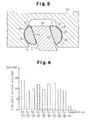
- Figure 6 is a graph showing the results of this test.
- the test results shown in Figure 6 demonstrate that seizure between the shoes 7 and the swash plates 40 takes much longer under severe use conditions in the compressors employing the shoes 7 of Examples 1 to 9 having the coating layers 11 compared with the compressor of the comparative example.
- a coating layer 11 containing tin as a major component is formed on the surface of each shoe 7. Accordingly, sliding resistance between the receiving recesses 46 of the piston 43 and the spherical surfaces 8 of the shoes 7 is reduced, and the sliding resistance between the swash plate 40 and the sliding surface 10 of the shoe 7 is reduced. Accordingly, even when there is a shortage of lubricant in the compressor, smooth sliding of the swash plate 40 and the pistons 43 can be guarantied at the joints thereof to control sliding resistance at the joints.
- the shoes 44 can move smoothly along the inner surfaces of the receiving recesses 46 under the action of the coating layer 11 formed on the spherical surfaces 8. As a result, the load acting between the sliding surface 10 of each shoe 7 and the swash plate 40 is moderated to reduce sliding resistance between the sliding surface 10 and the swash plate 40.
- the coating layer 11 is also present on the sliding surface 10 of the shoe 7, thus, the sliding resistance between the sliding surface 10 and the swash plate 40 can be further reduced. Therefore, when the discharge capacity of a compressor is to be increased, even if the sizes of the pistons 43 and the swash plate 40 are increased without changing the size of the shoes 7, no problems arise due to an increase in the sliding resistance.
- the coating layer 11 that contains tin as the major component formed on the surface of each shoe 7, which is made of a ferrous metal, can protect the shoe 7 from rusting.
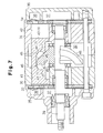
- the present invention may be embodied, for example, in a single-headed piston swash plate type compressor, a variable volume type compressor, which can adjust discharge volume by changing the tilt angle of the swash plate, a wave cam type compressor as shown in Figure 7, or the like.
- a wave cam type compressor as shown in Figure 7, or the like.
- this wave cam type compressor has a wave cam 48 having a wavy cam surface in place of the swash plate 40 in the compressor shown in Figure 1.
- the sliding surface 45 of each shoe 44 is designed to make sliding contact with the front cam surface or rear cam surface of the wave cam 48.
- each piston 43 is adapted to reciprocate twice or more (twice in Figure 7) per revolution of the drive shaft 39, and the shoes 44 are required to follow the complicated cam surfaces as the cam surfaces produce displacement. Accordingly, in wave cam type compressors, compared with the swash plate type compressors, the conditions between the shoes 44 and the pistons 43 and between the shoes 44 and the wave cam 48 are more harsh. Accordingly, a reduction in the sliding resistance occurring at the junction of the wave cam 48 and the pistons 43 is important so that the wave cam type compressor can perform stable compression.
- the pistons 43 may be replaced with the pistons 1 as described in the foregoing first embodiment, or the shoes 44 may be replaced with the shoes 7 as described in the foregoing second embodiment.
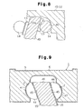
- each cam follower may consist of a slipper 13, which makes sliding contact with the swash plate 40, and a ball 14, which engages a recess 13a of the slipper 13.
- the ball 14 is slidably engaged in the receiving recess 46 of the piston 43.
- the pistons 43 may be replaced with the pistons 1 as described in the foregoing first embodiment, or the coating layer 11 as formed on the shoe 7 in the foregoing second embodiment may be formed on the slipper 13 or the ball 14 or both.
- cam follower shown in Figure 8 may be applied to the above-described wave cam type compressor shown in Figure 7.
- a coating layer 15 that contains tin as the major component is formed on each surface of the swash plate 40, which makes sliding contact with the shoes 44, as shown in Figure 9.
- the composition of the coating layer 15 may be the same as that of the coating layer 6 of the piston 1.
- a coating layer containing tin as the major component may be formed on the sliding surface 45 of each shoe 44 instead of forming the coating layers 15 on each side of the swash plate 40.
- the shoe 7 in the second embodiment may be given the coating layer 11 only at the sliding surface 10, and such shoes 7 may be employed as the shoes in the first embodiment.
- the coating layer 6 may be formed only at the receiving recesses 2 of the pistons 1.
- the coating layer 11 may be formed on either the spherical surface 8 or the sliding surface 10 of each shoe 7.
- the coating layers 15 may be formed on each side of the swash plate 40 as described in (3).
- the piston 1 in the first embodiment i.e., the piston 1 having the coating layer 6, may be employed.
- the surface of the main body 5 of the piston 1 may be subjected to pretreatment such as alumite treatment, manganese phosphate treatment, zinc phosphate treatment or zinc plating treatment prior to formation of the coating layer 6 on the main body 5.
- pretreatment such as alumite treatment, manganese phosphate treatment, zinc phosphate treatment or zinc plating treatment prior to formation of the coating layer 6 on the main body 5.
- an alumina ceramic (A1203) layer may be formed on the sliding surface 10 of the main body 12 of each shoe 7 and the sliding surface 45 of each shoe 44.Thus, the sliding resistance of the shoes with the swash plate 40 can further be reduced.
- the ratio of tin to other metals also present in the coating layer 6 or 11 may be suitably changed depending on the desired performance of the compressor.
- the content of copper is desirably changed to within the range of 0.1 % by weight to 50 % by weight. If the content of copper is smaller than 0.1 % by weight, densification and reinforcement of the coating layer 6 or 11 cannot be fully achieved, and the effect to be brought about by incorporation of copper cannot be achieved. If the content of copper is greater than 50 % by weight, the self-lubricating action of tin cannot be fully achieved, which results in increased sliding resistance.
- the fluororesin powder or the molybdenum disulfide powder incorporated in the coating layer 6 or 11 as a solid lubricant may be replaced with a carbon powder, a boron nitride powder, or the like.
- the coating layer 6 or 11 may not be formed by means of wet plating process such as electrolytic plating and chemical plating but may be formed utilizing a CVD method or a dry plating method such as vacuum deposition, sputtering, ion plating and PVD.
- a composite plating method may be employed.
- the thickness of the coating layer 6 or 11 may be suitably adjusted in the range of 1 to 5 mu m. If the coating layer 6 or 11 has a thickness of smaller than 1 mu m, the coefficient of friction cannot be sufficiently reduced. If the coating layer 6 or 11 has a thickness greater than 5 mu m, a problem is likely to occur in the rigidity of the layer, and the coating layer 6 or 11 may separate.
Landscapes
- Engineering & Computer Science (AREA)
- Manufacturing & Machinery (AREA)
- Mechanical Engineering (AREA)
- General Engineering & Computer Science (AREA)
- Compressors, Vaccum Pumps And Other Relevant Systems (AREA)
Priority Applications (2)
| Application Number | Priority Date | Filing Date | Title |
|---|---|---|---|
| EP03024463A EP1384887B1 (fr) | 1996-05-08 | 1996-05-08 | Compresseur à déplacement alternatif |
| DE69635002T DE69635002T2 (de) | 1996-05-08 | 1996-05-08 | Kolbenkompressor |
Applications Claiming Priority (2)
| Application Number | Priority Date | Filing Date | Title |
|---|---|---|---|
| EP96913701A EP0838590B1 (fr) | 1996-05-08 | 1996-05-08 | Compresseur a deplacement alternatif |
| EP03024463A EP1384887B1 (fr) | 1996-05-08 | 1996-05-08 | Compresseur à déplacement alternatif |
Related Parent Applications (1)
| Application Number | Title | Priority Date | Filing Date |
|---|---|---|---|
| EP96913701A Division EP0838590B1 (fr) | 1996-05-08 | 1996-05-08 | Compresseur a deplacement alternatif |
Publications (3)
| Publication Number | Publication Date |
|---|---|
| EP1384887A2 true EP1384887A2 (fr) | 2004-01-28 |
| EP1384887A3 EP1384887A3 (fr) | 2004-07-21 |
| EP1384887B1 EP1384887B1 (fr) | 2005-07-27 |
Family
ID=29797379
Family Applications (1)
| Application Number | Title | Priority Date | Filing Date |
|---|---|---|---|
| EP03024463A Expired - Lifetime EP1384887B1 (fr) | 1996-05-08 | 1996-05-08 | Compresseur à déplacement alternatif |
Country Status (1)
| Country | Link |
|---|---|
| EP (1) | EP1384887B1 (fr) |
Family Cites Families (5)
| Publication number | Priority date | Publication date | Assignee | Title |
|---|---|---|---|---|
| JPS5786580A (en) * | 1980-11-19 | 1982-05-29 | Toyoda Autom Loom Works Ltd | Piston for swash plate type compressor |
| JPS6241980A (ja) * | 1985-08-16 | 1987-02-23 | Taiho Kogyo Co Ltd | 斜板式コンプレツサ用シユ− |
| JPH0697033B2 (ja) * | 1988-11-11 | 1994-11-30 | 株式会社豊田自動織機製作所 | 斜板式圧縮機 |
| JP3007644B2 (ja) * | 1989-10-26 | 2000-02-07 | 株式会社豊田自動織機製作所 | 斜板式圧縮機 |
| JP3039762B2 (ja) * | 1995-03-07 | 2000-05-08 | 株式会社豊田自動織機製作所 | 往復動型圧縮機 |
-
1996
- 1996-05-08 EP EP03024463A patent/EP1384887B1/fr not_active Expired - Lifetime
Also Published As
| Publication number | Publication date |
|---|---|
| EP1384887A3 (fr) | 2004-07-21 |
| EP1384887B1 (fr) | 2005-07-27 |
Similar Documents
| Publication | Publication Date | Title |
|---|---|---|
| US5943941A (en) | Reciprocating compressor | |
| EP1035326B1 (fr) | Revêtement de compresseur | |
| US5056417A (en) | Swash plate type compressor having a surface coating layer on the surface of swash plate | |
| US6289785B1 (en) | Swash plate type compressor | |
| EP1036938B1 (fr) | Revêtement de compresseur | |
| EP0838590B1 (fr) | Compresseur a deplacement alternatif | |
| EP0890743A2 (fr) | Plateau oscillant pour compresseur à plateau oscillant | |
| US6584886B2 (en) | Compressor | |
| US6192784B1 (en) | Swash plate compressor | |
| EP0943801A1 (fr) | Compresseur a plateau oscillant | |
| EP1172555A2 (fr) | Disposition de patin gant pour compresseur à plateau en biais | |
| JP2002317757A (ja) | 容量可変型斜板式圧縮機における斜板 | |
| US20030096134A1 (en) | Sliding member for compressor | |
| EP1068452B1 (fr) | Plateau oscillant presentant un revetement en alliage de cobalt et d'etain | |
| EP1384887B1 (fr) | Compresseur à déplacement alternatif | |
| EP0911517B1 (fr) | Compresseur à plateau en biais | |
| CN1127619C (zh) | 旋转斜盘式压缩机 | |
| JP3007644B2 (ja) | 斜板式圧縮機 | |
| EP1074737A2 (fr) | Surface de lubrification sur le siège de piston d'un compresseur de réfrigérant à plateau en biais | |
| JPH0526155A (ja) | 容量可変斜板式コンプレツサ | |
| DE29624456U1 (de) | Kompressor |
Legal Events
| Date | Code | Title | Description |
|---|---|---|---|
| PUAI | Public reference made under article 153(3) epc to a published international application that has entered the european phase |
Free format text: ORIGINAL CODE: 0009012 |
|
| AC | Divisional application: reference to earlier application |
Ref document number: 0838590 Country of ref document: EP Kind code of ref document: P |
|
| AK | Designated contracting states |
Kind code of ref document: A2 Designated state(s): DE FR IT |
|
| PUAL | Search report despatched |
Free format text: ORIGINAL CODE: 0009013 |
|
| AK | Designated contracting states |
Kind code of ref document: A3 Designated state(s): DE FR IT |
|
| RIC1 | Information provided on ipc code assigned before grant |
Ipc: 7F 04B 27/10 B Ipc: 7F 04B 27/08 A |
|
| GRAP | Despatch of communication of intention to grant a patent |
Free format text: ORIGINAL CODE: EPIDOSNIGR1 |
|
| 17P | Request for examination filed |
Effective date: 20040928 |
|
| AKX | Designation fees paid |
Designated state(s): DE FR IT |
|
| GRAS | Grant fee paid |
Free format text: ORIGINAL CODE: EPIDOSNIGR3 |
|
| GRAA | (expected) grant |
Free format text: ORIGINAL CODE: 0009210 |
|
| AC | Divisional application: reference to earlier application |
Ref document number: 0838590 Country of ref document: EP Kind code of ref document: P |
|
| AK | Designated contracting states |
Kind code of ref document: B1 Designated state(s): DE FR IT |
|
| REF | Corresponds to: |
Ref document number: 69635002 Country of ref document: DE Date of ref document: 20050901 Kind code of ref document: P |
|
| ET | Fr: translation filed | ||
| PLBE | No opposition filed within time limit |
Free format text: ORIGINAL CODE: 0009261 |
|
| STAA | Information on the status of an ep patent application or granted ep patent |
Free format text: STATUS: NO OPPOSITION FILED WITHIN TIME LIMIT |
|
| 26N | No opposition filed |
Effective date: 20060428 |
|
| REG | Reference to a national code |
Ref country code: FR Ref legal event code: PLFP Year of fee payment: 20 |
|
| PGFP | Annual fee paid to national office [announced via postgrant information from national office to epo] |
Ref country code: DE Payment date: 20150506 Year of fee payment: 20 |
|
| PGFP | Annual fee paid to national office [announced via postgrant information from national office to epo] |
Ref country code: IT Payment date: 20150515 Year of fee payment: 20 Ref country code: FR Payment date: 20150508 Year of fee payment: 20 |
|
| REG | Reference to a national code |
Ref country code: DE Ref legal event code: R071 Ref document number: 69635002 Country of ref document: DE |