EP1384986A2 - System und Verfahren zum Erfassen von Daten über Spin und Verwindung beim Ziehen von optischen Fasern - Google Patents
System und Verfahren zum Erfassen von Daten über Spin und Verwindung beim Ziehen von optischen Fasern Download PDFInfo
- Publication number
- EP1384986A2 EP1384986A2 EP03014200A EP03014200A EP1384986A2 EP 1384986 A2 EP1384986 A2 EP 1384986A2 EP 03014200 A EP03014200 A EP 03014200A EP 03014200 A EP03014200 A EP 03014200A EP 1384986 A2 EP1384986 A2 EP 1384986A2
- Authority
- EP
- European Patent Office
- Prior art keywords
- optical fiber
- diameter
- fiber
- spin
- determining
- Prior art date
- Legal status (The legal status is an assumption and is not a legal conclusion. Google has not performed a legal analysis and makes no representation as to the accuracy of the status listed.)
- Withdrawn
Links
- 239000013307 optical fiber Substances 0.000 title claims abstract description 89
- 238000000034 method Methods 0.000 title claims abstract description 27
- 239000000835 fiber Substances 0.000 claims abstract description 97
- 238000005259 measurement Methods 0.000 claims abstract description 51
- 230000000737 periodic effect Effects 0.000 claims abstract description 15
- 238000009987 spinning Methods 0.000 claims description 23
- 238000012545 processing Methods 0.000 claims description 8
- 238000012544 monitoring process Methods 0.000 claims description 7
- 238000004519 manufacturing process Methods 0.000 abstract description 13
- 238000001816 cooling Methods 0.000 abstract description 2
- 230000000694 effects Effects 0.000 abstract 1
- 230000007246 mechanism Effects 0.000 description 7
- 239000011248 coating agent Substances 0.000 description 6
- 238000000576 coating method Methods 0.000 description 6
- 238000004458 analytical method Methods 0.000 description 4
- 238000004364 calculation method Methods 0.000 description 4
- 230000000875 corresponding effect Effects 0.000 description 4
- 230000010287 polarization Effects 0.000 description 4
- 230000005540 biological transmission Effects 0.000 description 3
- 230000008859 change Effects 0.000 description 3
- 230000003247 decreasing effect Effects 0.000 description 3
- 230000008569 process Effects 0.000 description 3
- 230000015556 catabolic process Effects 0.000 description 2
- 230000006378 damage Effects 0.000 description 2
- 238000006731 degradation reaction Methods 0.000 description 2
- 239000006185 dispersion Substances 0.000 description 2
- 238000001914 filtration Methods 0.000 description 2
- 230000010354 integration Effects 0.000 description 2
- 238000012546 transfer Methods 0.000 description 2
- 230000002411 adverse Effects 0.000 description 1
- 230000015572 biosynthetic process Effects 0.000 description 1
- 230000002596 correlated effect Effects 0.000 description 1
- 230000001419 dependent effect Effects 0.000 description 1
- 230000001066 destructive effect Effects 0.000 description 1
- 238000012681 fiber drawing Methods 0.000 description 1
- 239000002657 fibrous material Substances 0.000 description 1
- 239000011521 glass Substances 0.000 description 1
- 230000003116 impacting effect Effects 0.000 description 1
- 238000011065 in-situ storage Methods 0.000 description 1
- 238000013507 mapping Methods 0.000 description 1
- 239000000463 material Substances 0.000 description 1
- 238000012067 mathematical method Methods 0.000 description 1
- 238000002844 melting Methods 0.000 description 1
- 230000008018 melting Effects 0.000 description 1
- 238000012986 modification Methods 0.000 description 1
- 230000004048 modification Effects 0.000 description 1
- 230000003287 optical effect Effects 0.000 description 1
- 230000000704 physical effect Effects 0.000 description 1
- 230000001902 propagating effect Effects 0.000 description 1
- 239000007787 solid Substances 0.000 description 1
- 238000010183 spectrum analysis Methods 0.000 description 1
Images




Classifications
-
- C—CHEMISTRY; METALLURGY
- C03—GLASS; MINERAL OR SLAG WOOL
- C03B—MANUFACTURE, SHAPING, OR SUPPLEMENTARY PROCESSES
- C03B37/00—Manufacture or treatment of flakes, fibres, or filaments from softened glass, minerals, or slags
- C03B37/01—Manufacture of glass fibres or filaments
- C03B37/02—Manufacture of glass fibres or filaments by drawing or extruding, e.g. direct drawing of molten glass from nozzles; Cooling fins therefor
- C03B37/025—Manufacture of glass fibres or filaments by drawing or extruding, e.g. direct drawing of molten glass from nozzles; Cooling fins therefor from reheated softened tubes, rods, fibres or filaments, e.g. drawing fibres from preforms
- C03B37/027—Fibres composed of different sorts of glass, e.g. glass optical fibres
- C03B37/02745—Fibres having rotational spin around the central longitudinal axis, e.g. alternating +/- spin to reduce polarisation mode dispersion
-
- G—PHYSICS
- G01—MEASURING; TESTING
- G01M—TESTING STATIC OR DYNAMIC BALANCE OF MACHINES OR STRUCTURES; TESTING OF STRUCTURES OR APPARATUS, NOT OTHERWISE PROVIDED FOR
- G01M11/00—Testing of optical apparatus; Testing structures by optical methods not otherwise provided for
- G01M11/08—Testing mechanical properties
- G01M11/088—Testing mechanical properties of optical fibres; Mechanical features associated with the optical testing of optical fibres
-
- C—CHEMISTRY; METALLURGY
- C03—GLASS; MINERAL OR SLAG WOOL
- C03B—MANUFACTURE, SHAPING, OR SUPPLEMENTARY PROCESSES
- C03B2203/00—Fibre product details, e.g. structure, shape
- C03B2203/10—Internal structure or shape details
- C03B2203/18—Axial perturbations, e.g. in refractive index or composition
- C03B2203/19—Alternating positive/negative spins or twists
-
- C—CHEMISTRY; METALLURGY
- C03—GLASS; MINERAL OR SLAG WOOL
- C03B—MANUFACTURE, SHAPING, OR SUPPLEMENTARY PROCESSES
- C03B2203/00—Fibre product details, e.g. structure, shape
- C03B2203/36—Dispersion modified fibres, e.g. wavelength or polarisation shifted, flattened or compensating fibres (DSF, DFF, DCF)
-
- C—CHEMISTRY; METALLURGY
- C03—GLASS; MINERAL OR SLAG WOOL
- C03B—MANUFACTURE, SHAPING, OR SUPPLEMENTARY PROCESSES
- C03B2205/00—Fibre drawing or extruding details
- C03B2205/06—Rotating the fibre fibre about its longitudinal axis
-
- Y—GENERAL TAGGING OF NEW TECHNOLOGICAL DEVELOPMENTS; GENERAL TAGGING OF CROSS-SECTIONAL TECHNOLOGIES SPANNING OVER SEVERAL SECTIONS OF THE IPC; TECHNICAL SUBJECTS COVERED BY FORMER USPC CROSS-REFERENCE ART COLLECTIONS [XRACs] AND DIGESTS
- Y02—TECHNOLOGIES OR APPLICATIONS FOR MITIGATION OR ADAPTATION AGAINST CLIMATE CHANGE
- Y02P—CLIMATE CHANGE MITIGATION TECHNOLOGIES IN THE PRODUCTION OR PROCESSING OF GOODS
- Y02P40/00—Technologies relating to the processing of minerals
- Y02P40/50—Glass production, e.g. reusing waste heat during processing or shaping
- Y02P40/57—Improving the yield, e-g- reduction of reject rates
Definitions
- This invention relates to systems and methods for obtaining spin and mechanical twist data for an optical fiber. Specifically, the systems and methods of the present invention measures the rate of rotation imparted into a molten fiber as well as the rate of mechanical rotation introduced on a cooled fiber as it is drawn from a preform.
- PMD polarization mode dispersion
- the fiber material in the hot zone is torsionally deformed and results in the deformation being 'frozen' into the fiber as it cools from its molten state.
- the fiber Once cooled, the fiber exhibits a permanent "spin", i.e., a permanent torsional deformation.
- the amount of spin that is actually introduced into the molten fiber is not always the same as the amount that is attempted to be introduced. There are various factors affecting the rotational transfer imparted into the fiber. For example, the fiber may 'slip' on the rollers that impart the twist and the length of fiber span between the molten fiber and the spinning apparatus impacts the degree of cooling, and thus the amount of spin actually imparted. Consequently, the spin actually introduced compared to the spin attempted to be introduced is less than 100% and cannot always be predicted at any given moment in time.
- a mechanism for measuring the actual amount of spin imparted at any moment in time during production is advantageous to verify that the appropriate levels of spin are introduced into the fiber.
- the existence of the imparted spin can be readily ascertained, e.g., by microscopic examination of bubbles in the fiber to determine rotation of core ovality or eccentricity, or by means of a traveling magneto-optic modulator, as used by M. J. Marrone et al., Optics Letters, Vol. 12(1), p. 60.
- microscopic examination of bubbles in the fiber or similar techniques require destruction of the fiber and are undesirable. Such analysis provides little opportunity to monitor the formation of spin in real time and affect the manufacturing in situ. Further, microscopic examination is both time and labor consuming, in addition to being destructive. Additionally, such examination only allows determination of spin at sampled points - determination of spin all along a fiber cable would be impractical using this method and would destroy the optical fiber.
- spin refers to the rotation introduced into the molten optical fiber
- 'twist' refers to the rotation introduced onto the cooled optical fiber.
- Spin is imparted into the molten fiber, and is permanently fixed when the fiber has cooled.
- Twist refers to the mechanical rotational force imposed on the optical fiber after it has cooled. Twist introduces torsional stresses on the fiber, and extreme amounts can cause microscopic cracks, and ultimately physical destruction of the fiber. It is desirable to reduce or eliminate twist introduced on the fiber.
- One method of reducing twist on optical fiber is to 'respool' the fiber by unwinding it and rewinding the fiber, which is also time consuming and labor intensive. It would be preferable to avoid or minimize the introduction of twist to acceptable levels during manufacturing. In either case, a method of measuring the levels of twist in the optical fiber during manufacturing is required. Therefore, there is a need for systems and methods for measuring twist introduced on optical fibers.
- a method for measuring spin imparted in optical fibers by measuring the diameter of an optical fiber as it is drawn from a molten preform, detecting the periodic minimum and maximum diameters, processing the diameter measurements and the draw rate to determine the spin imparted into the optical fiber.
- a system that measures the spin imparted into an optical fiber comprising an apparatus for drawing fiber from a molten preform, a measurement device measuring the diameter of the fiber as it is drawn, a processor receiving inputs regarding the fiber draw rate and diameter measurements and determining the spin rate in the optical fiber.
- a method of determining twist on an optical fiber by drawing an optical fiber, monitoring the rate of draw of said optical fiber, measuring a first diameter of the optical fiber at a first point as it is being drawn and detecting periodic diameter measurements, and processing said periodic diameter measurements and determining the twist on the optical fiber.
- a method for measuring rotations along the principle axis in an optical fiber where the optical fiber is drawn past a fiber diameter measuring device at a known draw rate, measurements of the diameter of the optical fiber is obtained by the fiber diameter measuring device, periodic changes in the diameter of the optical fiber is determined, and the periodic changes in the measurements is processed in conjunction with said known draw rate to measure the rotations along the principle axis of the optical fiber.
- PMD Polarization Mode Dispersion
- FIG. 1 illustrates an exemplary apparatus for manufacturing fiber optic apparatus according to the prior art.
- a preform 10 of pure glass is previously formed to provide the material for the optical fiber.
- the preform is heated by a heat source 15 using conventional means. Once the preform is heated to its melting point and a fiber has been pulled, an angular area called the neck-down 20 is formed.
- a single optical fiber 25 emerges from the preform in a semi-molten state and passes through a diameter measuring device 30 .
- the optical fiber continues to be pulled downward and passes through a coating applicator 40 that applies a coating to protect the optical fiber.
- the fiber may also pass through a unit 43 , which cures the optical coating, and a unit 45 that monitors the overall diameter after the coating has been applied.
- the optical fiber than encounters a spinning apparatus 60 that imparts a spin into the fiber.
- Such mechanisms have been described in previous patents and may incorporate rollers or take-up wheels 191 (see, for example, U.S. Patent 5,298,047).
- the optical fiber then encounters a series of guide rollers 65 comprising individual rollers 192, 193 and eventually to a capstan 70 pulling the fiber.
- the fiber is then wrapped around a spool (not shown).
- the spinning apparatus 60 imparts an angular movement ⁇ 1 55 to the fiber.
- the spinning apparatus 60 is located at a distance from the neck down region 20 such that the fiber has cooled down somewhat by the time the coating is applied and further cooled once it comes into contact with the spinning apparatus.
- a different angular movement, ⁇ 2 28 is impacted near the neck-down region 20 with the value of ⁇ 1 > ⁇ 2 . This is due in part to:
- Figure 2 depicts an ellipse 150 in reference to an X axis 120 and Y axis 110 which are orthogonal to one another.
- the ellipse 150 can be described as having a major axis a 130 and a minor axis b 140 which are orthogonal to each other.
- the ellipse can be described as having an angle of rotation, ⁇ 160 that is measured between the major axis a 130 and the X axis 120 .
- the sideview diameter D 170 is a function of ⁇ , and in the embodiment shown, the maximum sideview diameter occurs when ⁇ is equal to 0 or 180 degrees. Conversely, the minimum sideview diameter occurs when ⁇ is equal to 90 or 270 degrees.
- d 0 is the average diameter
- di is the harmonic amplitude
- ⁇ is the relative azimuthal position
- ⁇ i is the relative phase(rotation).
- the second mode harmonics is the dominated one.
- the diameter measurement would exhibit sinusoidal characteristics.
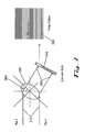
- the diameter of the optical fiber is measured by the diameter monitor device (also called a diameter measurement device) 30 according to one embodiment of the present invention.
- a variety of methods may be used to measure the diameter of the fiber, and the present invention can be illustrated using a variety of diameter measurement devices.
- One such example is illustrated in Figure 3.
- the diameter measurement device in this embodiment of the present invention monitors a fringe pattern of a light beam propagating through the optical fiber, where the fringe patter is affected by the cross section of the optical fiber.
- the diameter measurement device directs laser light beams 310 through the cross section of the optical fiber 320 .
- the optical fiber will bend the light rays according to well known physical properties and create a fringe pattern after they pass through the fiber.
- the rays 330 then strike a line-scan-diode 340 that creates electrical signals correlating to the developed fringe pattern 350 which is dependent on the thickness of the fiber.
- the angle ⁇ 360 which represents the position of the cross section of the optical fiber, the signal from the line scan diode is modulated.
- the diameter monitor will sense a change in diameter based on the angle ⁇ 360 .
- Table 1 indicates the change in diameter according to ⁇ .
- the diameter measurements would exhibit sinusoidal characteristics, periodically increasing and decreasing as the fiber is rotated.
- the diameter of the fiber measured is impacted by a variety of factors other than the spin rate, including the temperature of the heat source and potential temperature variation across the preform, rate of fiber draw, presence of microscopic air bubbles, and lateral mechanical vibrations in the optical fiber.
- Figure 3A illustrates the functions of the system of the present invention according to the present invention embodying the diameter measurement system illustrated in Figure 3.
- the diameter measurement device 386 receives input signals 385 from the line scan diode.
- the diameter measurement device 386 produces output 387 representing the diameter measurement signals as a function of time.
- These signals are filtered by the high/low pass filters 388 which produced the filtered diameter measurements as a function of time 389 .
- These are received by a processor 390 which processes the data according to the principles of the current invention to produce spin and twist data 392 .
- Figure 5 illustrates the fiber diameter measurements, but with an expanded time scale. As the fiber is drawn and simultaneously spun, the profile of the measured diameter periodically exhibits maximum and minimum values. As is evidenced in Figure 5, the diameter along the major axis 130 of the fiber (as illustrated in Figure 2) exhibits periodic peaks 500 of approximately about 124.82 - 124.87 ⁇ m. Further, as evidenced in Figure 5, the diameter along the minor axis 140 is about 124.64 - 124.67 ⁇ m based on the periodic valleys 510 . The average diameter can be estimated at about 124.75 ⁇ m 520 .
- Figure 5 illustrates the presence of higher frequency signals causing the 'jagged' waveform.
- the above factors cause changes in the diameter readings and can adversely impact the determination of the spin rate. Consequently, the measurement diameter signal 387 of Figure 3A must be filtered using standard filtering techniques to remove spurious noise signals.
- the signal is subjected to a high pass filter 388 to remove high frequency components that represent spurious noise signals.
- the signal is also subjected to a low pass filter 388 to remove certain low frequency signals corresponding to inherent variations of the average diameter of the optical fiber along its length.
- the low-pass filter results in a constant average diameter signal and does not filter out the frequency components of the signal corresponding to the diameter variations introduced by the spin.
- the frequency of the signal associated with diameter variations due to spin is a higher frequency than the diameter variations associated with changes in the average diameter.
- Figure 6 also shows a normalized amplitude (i.e., the direct current component having been filtered out), so that the average diameter is zero.
- the determination of the number of spins over a given time period can be calculated in a variety of ways, but are based on a common principle. Namely, a single revolution of an elliptical fiber requires 360 degrees rotation of ⁇ . This can be determined by detecting the maximum diameter as a starting point and detecting the next maximum diameter (which corresponds to 180 degrees of rotation) and then detecting a second next maximum diameter (which corresponds to 360 degrees rotation). Alternatively, using the minimum diameter can be detected or the average of the diameter can be monitored, and the every fourth average diameter indication will signify a single rotation.
- a positive value 600 indicates an above average diameter that indicates a measurement along or partly along the major axis view while a negative value 610 indicates a measurement along or partly along the minor axis view.
- the relative increase/decrease of the value indicates the relative rotation with respect to the major and minor axis.
- Figure 7 illustrates a typical spin pattern for an optical fiber mapping the spin rate (turns/meter) as a function of time.
- calculation of the spin rate involves basic arithmetic operations that can be performed relatively quickly using general purpose microprocessors, and does not require complicated, processor intensive, Fast Fourier Transform calculations. Because the required computation processing power to calculate spin is relatively modest, calculating the spin rate can be performed in real-time allowing real-time adjustments and monitoring of the spinning apparatus 50 to achieve the desired spin rate. Further, by monitoring the take-up rate as determined by the rotation speed of the take up capstan 60 , the linear draw rate is known. This allows easy calculation of the real-time spin rate as a function over a length of optical fiber.
- Twist into the optical fiber can be introduced in a number of ways. Referring to Figure 1, if a rotation is introduced on the fiber 25 between the neckdown region 20 and the spinning device 60 , there is rotation introduced between the spinning device 60 and the take up roller 192 . This is likely to introduce twist onto the fiber that remains after the fiber passes capstan 70 . However, the prior art teaches the rotation introduced by the spinning device 60 alternates in direction (see e.g., Hart, Patent No. 5,298,047). Thus, the rotation may be clockwise for a first time period, and then counterclockwise in a second time period. If the number of rotations introduced in one time period is offset by the number of rotations in the opposite direction, then the net rotations introduced is zero which should minimize any twist introduced upon take-up.
- the spin data in Figure 7 illustrates a spin rate function with respect to time.
- the valleys 700 represent instances in which the fiber rotation direction is altered. In theory, a reversal of direction corresponds to a point in the fiber in which the rotation is zero. Given the speed at which rotation changes can occur and limitations on the resolution of the illustrative embodiments, the data in Figure 7 illustrates periodic valleys 700 which correspond to near zero rotations. For example, the peak during T 1 represents rotation in one direction, with rotation in the other direction occurring during T 2 . Alternatively, the data can be correlated with the direction of rotation, and the spin rate reflect the rotational direction resulting in a graph in which positive values reflect one rotational direction and negative values reflect the other rotational direction.
- T 1 710 illustrates a time period in which the rotation is in one direction
- T 2 720 illustrates a time period in which the rotation is in the other direction.
- the area 'under' the curve i.e., bounded by the curve and the X axis
- the net number of spins during T 1 is the same as the number of spins during T 2 , but in different directions, then the net number of spins during the time period is zero. This results in a net twist of zero on the fiber for that duration (the duration which corresponds to a given length of fiber). Similarly, if the net number of spins is almost zero, the net twist can be maintained at or below a certain maximum desired level.
- the system can measure spin and twist in real time, the result of the calculations performed on the data can be used to alter the spin rate, draw rate, or any other variable affecting the spin or twist in the fiber. Without real time measurements, real time control of the manufacturing is not possible. This system allows real time control of various parameters to minimize twist on the fiber.
- the system could detect the maximum and minimum diameters over a given time period.
- the derivative of the spin pattern could be calculated and used for determining when a major axis (maximum diameter) or minor axis (minimum diameter) has rotated passed the diameter measurement device.
- determining the number of major (or minor) axis during a time period and dividing by four produces the number of rotations per time period. Therefore, it is to be understood that the invention is not to be limited to the specific embodiments disclosed and that modifications and other embodiments and algorithms for determining rotations are intended to be included within the scope of the appended claims. Although specific terms are employed herein, they are used in a generic and descriptive sense only and not for purposes of limitation.
Landscapes
- Chemical & Material Sciences (AREA)
- Engineering & Computer Science (AREA)
- Organic Chemistry (AREA)
- Analytical Chemistry (AREA)
- General Life Sciences & Earth Sciences (AREA)
- Geochemistry & Mineralogy (AREA)
- Manufacturing & Machinery (AREA)
- Materials Engineering (AREA)
- Dispersion Chemistry (AREA)
- Life Sciences & Earth Sciences (AREA)
- Physics & Mathematics (AREA)
- General Physics & Mathematics (AREA)
- Length Measuring Devices By Optical Means (AREA)
- Manufacture, Treatment Of Glass Fibers (AREA)
- Optical Fibers, Optical Fiber Cores, And Optical Fiber Bundles (AREA)
- Testing Of Optical Devices Or Fibers (AREA)
Applications Claiming Priority (2)
| Application Number | Priority Date | Filing Date | Title |
|---|---|---|---|
| US10/202,560 US6791678B2 (en) | 2002-07-23 | 2002-07-23 | System and method for obtaining spin and mechanical twist data during optical fiber draw |
| US202560 | 2002-07-23 |
Publications (2)
| Publication Number | Publication Date |
|---|---|
| EP1384986A2 true EP1384986A2 (de) | 2004-01-28 |
| EP1384986A3 EP1384986A3 (de) | 2006-05-31 |
Family
ID=30000099
Family Applications (1)
| Application Number | Title | Priority Date | Filing Date |
|---|---|---|---|
| EP03014200A Withdrawn EP1384986A3 (de) | 2002-07-23 | 2003-06-24 | System und Verfahren zum Erfassen von Daten über Spin und Verwindung beim Ziehen von optischen Fasern |
Country Status (4)
| Country | Link |
|---|---|
| US (1) | US6791678B2 (de) |
| EP (1) | EP1384986A3 (de) |
| JP (1) | JP5116934B2 (de) |
| CN (1) | CN1289423C (de) |
Families Citing this family (14)
| Publication number | Priority date | Publication date | Assignee | Title |
|---|---|---|---|---|
| AU7788800A (en) * | 1999-10-29 | 2001-05-14 | Pirelli Cavi E Sistemi S.P.A. | Method of measuring the twist imparted to an optical fibre and procedure for processing an optical fibre using this method |
| US20080141723A1 (en) * | 2004-12-02 | 2008-06-19 | Franco Cocchini | Method, System and Device for Imparting a Predetermined Rotation to an Optical Fibre |
| US7317855B2 (en) * | 2004-12-16 | 2008-01-08 | Corning Incorporated | Method of imparting twist to optical fiber |
| JP4825430B2 (ja) * | 2005-02-22 | 2011-11-30 | 信越化学工業株式会社 | 光ファイバ母材のコア部非円率測定方法。 |
| JP4851368B2 (ja) * | 2007-03-05 | 2012-01-11 | 古河電気工業株式会社 | 光ファイバの製造方法 |
| EP2341377B1 (de) * | 2008-10-20 | 2017-10-04 | Sumitomo Electric Industries, Ltd. | Verfahren zum herstellen von optischer faser |
| US20150115548A1 (en) * | 2013-10-29 | 2015-04-30 | Virginia Sealing Products, Inc. | Composite gasket |
| JP6385472B2 (ja) | 2014-06-17 | 2018-09-05 | ヘレーウス クオーツ ノース アメリカ エルエルシーHeraeus Quartz North America LLC | 透明な円柱状製品を測定するための装置および方法 |
| CN107401988B (zh) * | 2017-09-08 | 2023-09-15 | 成都中住光纤有限公司 | 一种光纤涂覆同心度监测系统 |
| CN111620560B (zh) * | 2020-06-10 | 2021-11-09 | 长飞光纤光缆股份有限公司 | 一种拉丝光纤扭动控制装置、控制方法及多模光纤 |
| CN115093113B (zh) * | 2022-06-17 | 2023-12-05 | 中国工程物理研究院激光聚变研究中心 | 一种用于微纳光纤拉制的直径在线监控系统 |
| JP2024024846A (ja) * | 2022-08-10 | 2024-02-26 | 住友電気工業株式会社 | 光ファイバの製造方法及び光ファイバ |
| WO2025197835A1 (ja) * | 2024-03-19 | 2025-09-25 | 住友電気工業株式会社 | 線条体の製造方法および線条体の製造装置 |
| WO2026088958A1 (ja) * | 2024-10-23 | 2026-04-30 | 住友電気工業株式会社 | 光ファイバの捻じれ量測定方法および光ファイバの製造方法 |
Citations (2)
| Publication number | Priority date | Publication date | Assignee | Title |
|---|---|---|---|---|
| WO2001033184A1 (en) | 1999-10-29 | 2001-05-10 | Pirelli Cavi E Sistemi S.P.A. | Method of measuring the twist imparted to an optical fibre and procedure for processing an optical fibre using this method |
| US20020067488A1 (en) | 2000-11-10 | 2002-06-06 | Drake Fibre Technology B.V. | Method for measuring the spin in an optical fibre |
Family Cites Families (5)
| Publication number | Priority date | Publication date | Assignee | Title |
|---|---|---|---|---|
| DE3206144A1 (de) * | 1982-02-20 | 1983-09-01 | Licentia Patent-Verwaltungs-Gmbh, 6000 Frankfurt | Verfahren zur herstellung eines lichtwellenleiters |
| US5228893A (en) * | 1991-11-27 | 1993-07-20 | At&T Bell Laboratories | Optical fiber tension monitoring technique |
| US5298047A (en) | 1992-08-03 | 1994-03-29 | At&T Bell Laboratories | Method of making a fiber having low polarization mode dispersion due to a permanent spin |
| RU2166484C2 (ru) | 1996-01-22 | 2001-05-10 | Корнинг Инкорпорейтед | Оптическое волокно с модулируемым скручиванием для уменьшения дисперсии поляризационных мод (варианты), способ (варианты) и устройство для его изготовления, совокупность оптических волокон |
| EP0879436A1 (de) | 1996-02-05 | 1998-11-25 | Daniel L. Shelander | Vorrichtung und verfahren zur herstellung optischer kabel |
-
2002
- 2002-07-23 US US10/202,560 patent/US6791678B2/en not_active Expired - Lifetime
-
2003
- 2003-06-24 EP EP03014200A patent/EP1384986A3/de not_active Withdrawn
- 2003-07-22 CN CNB031787967A patent/CN1289423C/zh not_active Expired - Fee Related
- 2003-07-23 JP JP2003277969A patent/JP5116934B2/ja not_active Expired - Lifetime
Patent Citations (2)
| Publication number | Priority date | Publication date | Assignee | Title |
|---|---|---|---|---|
| WO2001033184A1 (en) | 1999-10-29 | 2001-05-10 | Pirelli Cavi E Sistemi S.P.A. | Method of measuring the twist imparted to an optical fibre and procedure for processing an optical fibre using this method |
| US20020067488A1 (en) | 2000-11-10 | 2002-06-06 | Drake Fibre Technology B.V. | Method for measuring the spin in an optical fibre |
Also Published As
| Publication number | Publication date |
|---|---|
| US20040017557A1 (en) | 2004-01-29 |
| US6791678B2 (en) | 2004-09-14 |
| JP2004051482A (ja) | 2004-02-19 |
| JP5116934B2 (ja) | 2013-01-09 |
| CN1478743A (zh) | 2004-03-03 |
| EP1384986A3 (de) | 2006-05-31 |
| CN1289423C (zh) | 2006-12-13 |
Similar Documents
| Publication | Publication Date | Title |
|---|---|---|
| US6791678B2 (en) | System and method for obtaining spin and mechanical twist data during optical fiber draw | |
| US6859596B2 (en) | Systems and methods for forming ultra-low PMD optical fiber using amplitude and frequency keyed fiber spin functions | |
| JP3226283B2 (ja) | 偏光モード分散を減少させるためにスピンを変調させた光ファイバ並びにその製造方法および装置 | |
| US5228893A (en) | Optical fiber tension monitoring technique | |
| EP1226415B1 (de) | Verfahren zur messung des twists verliehen an einen optischen fiber und vorgehen bei dem verfahren zur verarbeitung eines optischen fibers | |
| US6937325B2 (en) | Method and apparatus for measuring eccentricity in a optical fiber | |
| EP1725853B1 (de) | Verfahren zur bestimmung der spinnmerkmalen von optischen spinnfasern | |
| EP1817263B1 (de) | Verfahren, system und vorrichtung zum versehen einer lichtleitfaser mit einer vorbestimmten drehung | |
| EP1578699B1 (de) | Verfahren zum herstellen einer optischen faser mit geringen polarisationsmodendispersion | |
| DK2033029T3 (en) | Optical fiber with sinusoidal spin function | |
| EP1231458B1 (de) | Verfahren zur Messung der Verdrehung in einer optischen Faser | |
| CN101119938A (zh) | 对光纤赋予预定转动的方法、系统和设备 |
Legal Events
| Date | Code | Title | Description |
|---|---|---|---|
| PUAI | Public reference made under article 153(3) epc to a published international application that has entered the european phase |
Free format text: ORIGINAL CODE: 0009012 |
|
| AK | Designated contracting states |
Kind code of ref document: A2 Designated state(s): AT BE BG CH CY CZ DE DK EE ES FI FR GB GR HU IE IT LI LU MC NL PT RO SE SI SK TR |
|
| AX | Request for extension of the european patent |
Extension state: AL LT LV MK |
|
| PUAL | Search report despatched |
Free format text: ORIGINAL CODE: 0009013 |
|
| AK | Designated contracting states |
Kind code of ref document: A3 Designated state(s): AT BE BG CH CY CZ DE DK EE ES FI FR GB GR HU IE IT LI LU MC NL PT RO SE SI SK TR |
|
| AX | Request for extension of the european patent |
Extension state: AL LT LV MK |
|
| RIC1 | Information provided on ipc code assigned before grant |
Ipc: C03B 37/025 20060101ALI20060407BHEP Ipc: C03B 37/027 20060101ALI20060407BHEP Ipc: G01M 11/00 20060101AFI20031103BHEP |
|
| 17P | Request for examination filed |
Effective date: 20061030 |
|
| AKX | Designation fees paid |
Designated state(s): FR GB |
|
| REG | Reference to a national code |
Ref country code: DE Ref legal event code: 8566 |
|
| 17Q | First examination report despatched |
Effective date: 20091006 |
|
| RAP1 | Party data changed (applicant data changed or rights of an application transferred) |
Owner name: OFS FITEL, LLC |
|
| STAA | Information on the status of an ep patent application or granted ep patent |
Free format text: STATUS: THE APPLICATION IS DEEMED TO BE WITHDRAWN |
|
| 18D | Application deemed to be withdrawn |
Effective date: 20160105 |