EP1385227A2 - Empilement de piles à combustible pour un véhicule - Google Patents
Empilement de piles à combustible pour un véhicule Download PDFInfo
- Publication number
- EP1385227A2 EP1385227A2 EP03254609A EP03254609A EP1385227A2 EP 1385227 A2 EP1385227 A2 EP 1385227A2 EP 03254609 A EP03254609 A EP 03254609A EP 03254609 A EP03254609 A EP 03254609A EP 1385227 A2 EP1385227 A2 EP 1385227A2
- Authority
- EP
- European Patent Office
- Prior art keywords
- fuel cell
- assembly
- cell stack
- separators
- stacking direction
- Prior art date
- Legal status (The legal status is an assumption and is not a legal conclusion. Google has not performed a legal analysis and makes no representation as to the accuracy of the status listed.)
- Ceased
Links
- 239000000446 fuel Substances 0.000 title claims description 112
- 239000002826 coolant Substances 0.000 claims description 23
- 239000000376 reactant Substances 0.000 claims description 18
- 239000003792 electrolyte Substances 0.000 claims description 13
- 230000000712 assembly Effects 0.000 claims description 9
- 238000000429 assembly Methods 0.000 claims description 9
- 239000012528 membrane Substances 0.000 abstract description 24
- 239000007789 gas Substances 0.000 description 58
- QVGXLLKOCUKJST-UHFFFAOYSA-N atomic oxygen Chemical compound [O] QVGXLLKOCUKJST-UHFFFAOYSA-N 0.000 description 32
- 239000002737 fuel gas Substances 0.000 description 32
- 239000001301 oxygen Substances 0.000 description 32
- 229910052760 oxygen Inorganic materials 0.000 description 32
- 238000009434 installation Methods 0.000 description 7
- LYCAIKOWRPUZTN-UHFFFAOYSA-N Ethylene glycol Chemical compound OCCO LYCAIKOWRPUZTN-UHFFFAOYSA-N 0.000 description 6
- 239000001257 hydrogen Substances 0.000 description 6
- 229910052739 hydrogen Inorganic materials 0.000 description 6
- 239000003054 catalyst Substances 0.000 description 5
- UFHFLCQGNIYNRP-UHFFFAOYSA-N Hydrogen Chemical compound [H][H] UFHFLCQGNIYNRP-UHFFFAOYSA-N 0.000 description 4
- 239000003014 ion exchange membrane Substances 0.000 description 4
- 238000010248 power generation Methods 0.000 description 4
- XLYOFNOQVPJJNP-UHFFFAOYSA-N water Substances O XLYOFNOQVPJJNP-UHFFFAOYSA-N 0.000 description 4
- OKTJSMMVPCPJKN-UHFFFAOYSA-N Carbon Chemical compound [C] OKTJSMMVPCPJKN-UHFFFAOYSA-N 0.000 description 3
- 229910052799 carbon Inorganic materials 0.000 description 3
- 238000006243 chemical reaction Methods 0.000 description 3
- 238000007599 discharging Methods 0.000 description 3
- 230000005611 electricity Effects 0.000 description 3
- -1 hydrogen ions Chemical class 0.000 description 3
- 238000009792 diffusion process Methods 0.000 description 2
- 238000004519 manufacturing process Methods 0.000 description 2
- 239000002245 particle Substances 0.000 description 2
- 238000007789 sealing Methods 0.000 description 2
- 229910001260 Pt alloy Inorganic materials 0.000 description 1
- 238000003487 electrochemical reaction Methods 0.000 description 1
- UQSQSQZYBQSBJZ-UHFFFAOYSA-N fluorosulfonic acid Chemical compound OS(F)(=O)=O UQSQSQZYBQSBJZ-UHFFFAOYSA-N 0.000 description 1
- 239000002828 fuel tank Substances 0.000 description 1
- 229920000642 polymer Polymers 0.000 description 1
- 239000005518 polymer electrolyte Substances 0.000 description 1
- 239000007787 solid Substances 0.000 description 1
- 239000007784 solid electrolyte Substances 0.000 description 1
Images







Classifications
-
- H—ELECTRICITY
- H01—ELECTRIC ELEMENTS
- H01M—PROCESSES OR MEANS, e.g. BATTERIES, FOR THE DIRECT CONVERSION OF CHEMICAL ENERGY INTO ELECTRICAL ENERGY
- H01M8/00—Fuel cells; Manufacture thereof
- H01M8/24—Grouping of fuel cells, e.g. stacking of fuel cells
- H01M8/249—Grouping of fuel cells, e.g. stacking of fuel cells comprising two or more groupings of fuel cells, e.g. modular assemblies
-
- B—PERFORMING OPERATIONS; TRANSPORTING
- B60—VEHICLES IN GENERAL
- B60K—ARRANGEMENT OR MOUNTING OF PROPULSION UNITS OR OF TRANSMISSIONS IN VEHICLES; ARRANGEMENT OR MOUNTING OF PLURAL DIVERSE PRIME-MOVERS IN VEHICLES; AUXILIARY DRIVES FOR VEHICLES; INSTRUMENTATION OR DASHBOARDS FOR VEHICLES; ARRANGEMENTS IN CONNECTION WITH COOLING, AIR INTAKE, GAS EXHAUST OR FUEL SUPPLY OF PROPULSION UNITS IN VEHICLES
- B60K1/00—Arrangement or mounting of electrical propulsion units
- B60K1/04—Arrangement or mounting of electrical propulsion units of the electric storage means for propulsion
-
- B—PERFORMING OPERATIONS; TRANSPORTING
- B60—VEHICLES IN GENERAL
- B60L—PROPULSION OF ELECTRICALLY-PROPELLED VEHICLES; SUPPLYING ELECTRIC POWER FOR AUXILIARY EQUIPMENT OF ELECTRICALLY-PROPELLED VEHICLES; ELECTRODYNAMIC BRAKE SYSTEMS FOR VEHICLES IN GENERAL; MAGNETIC SUSPENSION OR LEVITATION FOR VEHICLES; MONITORING OPERATING VARIABLES OF ELECTRICALLY-PROPELLED VEHICLES; ELECTRIC SAFETY DEVICES FOR ELECTRICALLY-PROPELLED VEHICLES
- B60L58/00—Methods or circuit arrangements for monitoring or controlling batteries or fuel cells, specially adapted for electric vehicles
- B60L58/30—Methods or circuit arrangements for monitoring or controlling batteries or fuel cells, specially adapted for electric vehicles for monitoring or controlling fuel cells
-
- B—PERFORMING OPERATIONS; TRANSPORTING
- B60—VEHICLES IN GENERAL
- B60L—PROPULSION OF ELECTRICALLY-PROPELLED VEHICLES; SUPPLYING ELECTRIC POWER FOR AUXILIARY EQUIPMENT OF ELECTRICALLY-PROPELLED VEHICLES; ELECTRODYNAMIC BRAKE SYSTEMS FOR VEHICLES IN GENERAL; MAGNETIC SUSPENSION OR LEVITATION FOR VEHICLES; MONITORING OPERATING VARIABLES OF ELECTRICALLY-PROPELLED VEHICLES; ELECTRIC SAFETY DEVICES FOR ELECTRICALLY-PROPELLED VEHICLES
- B60L58/00—Methods or circuit arrangements for monitoring or controlling batteries or fuel cells, specially adapted for electric vehicles
- B60L58/30—Methods or circuit arrangements for monitoring or controlling batteries or fuel cells, specially adapted for electric vehicles for monitoring or controlling fuel cells
- B60L58/32—Methods or circuit arrangements for monitoring or controlling batteries or fuel cells, specially adapted for electric vehicles for monitoring or controlling fuel cells for controlling the temperature of fuel cells, e.g. by controlling the electric load
- B60L58/33—Methods or circuit arrangements for monitoring or controlling batteries or fuel cells, specially adapted for electric vehicles for monitoring or controlling fuel cells for controlling the temperature of fuel cells, e.g. by controlling the electric load by cooling
-
- B—PERFORMING OPERATIONS; TRANSPORTING
- B60—VEHICLES IN GENERAL
- B60L—PROPULSION OF ELECTRICALLY-PROPELLED VEHICLES; SUPPLYING ELECTRIC POWER FOR AUXILIARY EQUIPMENT OF ELECTRICALLY-PROPELLED VEHICLES; ELECTRODYNAMIC BRAKE SYSTEMS FOR VEHICLES IN GENERAL; MAGNETIC SUSPENSION OR LEVITATION FOR VEHICLES; MONITORING OPERATING VARIABLES OF ELECTRICALLY-PROPELLED VEHICLES; ELECTRIC SAFETY DEVICES FOR ELECTRICALLY-PROPELLED VEHICLES
- B60L58/00—Methods or circuit arrangements for monitoring or controlling batteries or fuel cells, specially adapted for electric vehicles
- B60L58/30—Methods or circuit arrangements for monitoring or controlling batteries or fuel cells, specially adapted for electric vehicles for monitoring or controlling fuel cells
- B60L58/32—Methods or circuit arrangements for monitoring or controlling batteries or fuel cells, specially adapted for electric vehicles for monitoring or controlling fuel cells for controlling the temperature of fuel cells, e.g. by controlling the electric load
- B60L58/34—Methods or circuit arrangements for monitoring or controlling batteries or fuel cells, specially adapted for electric vehicles for monitoring or controlling fuel cells for controlling the temperature of fuel cells, e.g. by controlling the electric load by heating
-
- H—ELECTRICITY
- H01—ELECTRIC ELEMENTS
- H01M—PROCESSES OR MEANS, e.g. BATTERIES, FOR THE DIRECT CONVERSION OF CHEMICAL ENERGY INTO ELECTRICAL ENERGY
- H01M8/00—Fuel cells; Manufacture thereof
- H01M8/02—Details
- H01M8/0202—Collectors; Separators, e.g. bipolar separators; Interconnectors
- H01M8/0258—Collectors; Separators, e.g. bipolar separators; Interconnectors characterised by the configuration of channels, e.g. by the flow field of the reactant or coolant
-
- H—ELECTRICITY
- H01—ELECTRIC ELEMENTS
- H01M—PROCESSES OR MEANS, e.g. BATTERIES, FOR THE DIRECT CONVERSION OF CHEMICAL ENERGY INTO ELECTRICAL ENERGY
- H01M8/00—Fuel cells; Manufacture thereof
- H01M8/02—Details
- H01M8/0202—Collectors; Separators, e.g. bipolar separators; Interconnectors
- H01M8/0267—Collectors; Separators, e.g. bipolar separators; Interconnectors having heating or cooling means, e.g. heaters or coolant flow channels
-
- H—ELECTRICITY
- H01—ELECTRIC ELEMENTS
- H01M—PROCESSES OR MEANS, e.g. BATTERIES, FOR THE DIRECT CONVERSION OF CHEMICAL ENERGY INTO ELECTRICAL ENERGY
- H01M8/00—Fuel cells; Manufacture thereof
- H01M8/24—Grouping of fuel cells, e.g. stacking of fuel cells
- H01M8/241—Grouping of fuel cells, e.g. stacking of fuel cells with solid or matrix-supported electrolytes
-
- H—ELECTRICITY
- H01—ELECTRIC ELEMENTS
- H01M—PROCESSES OR MEANS, e.g. BATTERIES, FOR THE DIRECT CONVERSION OF CHEMICAL ENERGY INTO ELECTRICAL ENERGY
- H01M8/00—Fuel cells; Manufacture thereof
- H01M8/24—Grouping of fuel cells, e.g. stacking of fuel cells
- H01M8/2457—Grouping of fuel cells, e.g. stacking of fuel cells with both reactants being gaseous or vaporised
-
- H—ELECTRICITY
- H01—ELECTRIC ELEMENTS
- H01M—PROCESSES OR MEANS, e.g. BATTERIES, FOR THE DIRECT CONVERSION OF CHEMICAL ENERGY INTO ELECTRICAL ENERGY
- H01M8/00—Fuel cells; Manufacture thereof
- H01M8/24—Grouping of fuel cells, e.g. stacking of fuel cells
- H01M8/2465—Details of groupings of fuel cells
- H01M8/2483—Details of groupings of fuel cells characterised by internal manifolds
-
- H—ELECTRICITY
- H01—ELECTRIC ELEMENTS
- H01M—PROCESSES OR MEANS, e.g. BATTERIES, FOR THE DIRECT CONVERSION OF CHEMICAL ENERGY INTO ELECTRICAL ENERGY
- H01M2250/00—Fuel cells for particular applications; Specific features of fuel cell system
- H01M2250/20—Fuel cells in motive systems, e.g. vehicle, ship, plane
-
- H—ELECTRICITY
- H01—ELECTRIC ELEMENTS
- H01M—PROCESSES OR MEANS, e.g. BATTERIES, FOR THE DIRECT CONVERSION OF CHEMICAL ENERGY INTO ELECTRICAL ENERGY
- H01M4/00—Electrodes
- H01M4/86—Inert electrodes with catalytic activity, e.g. for fuel cells
- H01M4/8605—Porous electrodes
-
- Y—GENERAL TAGGING OF NEW TECHNOLOGICAL DEVELOPMENTS; GENERAL TAGGING OF CROSS-SECTIONAL TECHNOLOGIES SPANNING OVER SEVERAL SECTIONS OF THE IPC; TECHNICAL SUBJECTS COVERED BY FORMER USPC CROSS-REFERENCE ART COLLECTIONS [XRACs] AND DIGESTS
- Y02—TECHNOLOGIES OR APPLICATIONS FOR MITIGATION OR ADAPTATION AGAINST CLIMATE CHANGE
- Y02E—REDUCTION OF GREENHOUSE GAS [GHG] EMISSIONS, RELATED TO ENERGY GENERATION, TRANSMISSION OR DISTRIBUTION
- Y02E60/00—Enabling technologies; Technologies with a potential or indirect contribution to GHG emissions mitigation
- Y02E60/30—Hydrogen technology
- Y02E60/50—Fuel cells
-
- Y—GENERAL TAGGING OF NEW TECHNOLOGICAL DEVELOPMENTS; GENERAL TAGGING OF CROSS-SECTIONAL TECHNOLOGIES SPANNING OVER SEVERAL SECTIONS OF THE IPC; TECHNICAL SUBJECTS COVERED BY FORMER USPC CROSS-REFERENCE ART COLLECTIONS [XRACs] AND DIGESTS
- Y02—TECHNOLOGIES OR APPLICATIONS FOR MITIGATION OR ADAPTATION AGAINST CLIMATE CHANGE
- Y02T—CLIMATE CHANGE MITIGATION TECHNOLOGIES RELATED TO TRANSPORTATION
- Y02T90/00—Enabling technologies or technologies with a potential or indirect contribution to GHG emissions mitigation
- Y02T90/40—Application of hydrogen technology to transportation, e.g. using fuel cells
Definitions
- the present invention relates to a fuel cell stack formed by stacking electrolyte electrode assemblies and separators alternately.
- Each of the electrolyte electrode assemblies includes a pair of electrodes and an electrolyte interposed between the electrodes.
- the fuel cell stack is installed in a vehicle.
- a solid polymer electrolyte fuel cell employs a membrane electrode assembly (MEA) which comprises two electrodes (anode and cathode) and an electrolyte membrane interposed between the electrodes.
- MEA membrane electrode assembly
- the electrolyte membrane is a polymer ion exchange membrane (proton exchange membrane).
- the membrane electrode assembly is interposed between separators.
- the membrane electrode assembly and the separators make up a unit of a fuel cell (unit cell) for generating electricity.
- a fuel cell such as a hydrogen-containing gas
- the catalyst of the anode induces a chemical reaction of the fuel gas to split the hydrogen molecule into hydrogen ions (protons) and electrons.
- the hydrogen ions move toward the cathode through the electrolyte membrane which is appropriately humidified, and the electrons flow through an external circuit to the cathode, creating a DC electric current.
- An oxygen-containing gas or air is supplied to the cathode.
- the hydrogen ions from the anode combine with the electrons and oxygen to produce water.
- U.S. patent No. 5,662,184 discloses a type of the fuel cell stack for use in a vehicle.
- a fuel cell system is installed in a front box 2 of the vehicle 1.
- a radiator 3 is provided at a front region in the front box 2 of the vehicle 1.
- front wheels 5 are rotatably attached to opposite ends of a front axle 6.
- a motor 7 is driven to rotate the front axle 6.
- a pair of fuel cell stacks 8 are provided inside the vehicle frame 4 for supplying electricity to the motor 7.
- a compressor 9 for supplying an oxygen-containing gas is interposed between the fuel cell stacks 8.
- Each of the fuel cell stacks 8 includes a plurality of unit cells 8a stacked in a horizontal direction indicated by an arrow X.
- the space for installation may be different. Therefore, the arrangement of the unit cells 8a such as the shape of the electrodes of the unit cells 8a, and the dimensions of reactant gas passages need to be designed again. Further, the position for installing the fuel cell stack 8 often changes depending on the type of the vehicle. For example, the fuel cell stack 8 may be installed under the vehicle floor, in the front box, in the trunk box, or in the ceiling region of the vehicle. When the installation position changes, installation conditions such as the shape and dimensions of the space for installing the fuel cell stack 8 may be different.
- Japanese Laid-Open patent publication 11-67259 discloses a stack structure for a fuel cell having an inner manifold type separator in which each of an electrode part and a manifold part has a square shape. With the structure, a plurality of the fuel cells are arranged easily adjacent to each other in a horizontal direction or a vertical direction.
- the prior art 2 merely discloses the electrode part and the manifold part having a square shape, and the fuel cell stack may not be used practically in the vehicle application.
- the overall dimension of the fuel cell stacks in the lateral direction may be too large.
- the surface area of the electrodes of the unit cell may be small.
- a large number of unit cells need to be stacked for obtaining a high power output. Therefore, the dimension in the stacking direction of the unit cells is large, and the fuel cell stack can not be installed effectively in different positions in various types of vehicles, i.e., in spaces having different sizes and shapes.
- a main object of the present invention is to provide a fuel cell stack having a cell arrangement which can be easily installed in different positions in various types of vehicles.
- the fuel cell stack is used in various applications, and economically used particularly in the vehicle application.
- electrodes have a substantially square shape having a side length in a range of 140 mm to 200 mm
- separators have a substantially square shape having a side length in a range of 200 mm to 300 mm. Therefore, the size of the overall fuel cell stack is reduced effectively.
- the conditions (e.g., the shape and size of the space) for installing the fuel cell stack may change depending on the type of the vehicle.
- the electrodes have a substantially square shape having a side length in the range of 140 mm to 200 mm.
- the electrodes have a sufficiently large surface area. Thus, it is not necessary to stack a large number of unit cells for obtaining a desired power output.
- the surface area is less than 200 cm 2
- the stack volume needs to be significantly large.
- the surface area is greater than 400 cm 2 , the gas pressure loss in the electrode surface is large.
- the separators have a substantially square shape having a side length in the rage of 200 mm to 300 mm. Therefore, when the fuel cell stacks are juxtaposed laterally to form an assembly, the dimension of the assembly in the lateral direction is not excessively large.
- the fuel cell stack can be installed in different positions in various types of vehicles.
- a reactant gas supply passage and a reactant gas discharge passage extend through two parallel side portions of the separators in the stacking direction, and a coolant supply passage and a coolant discharge passage extend through other two parallel side portions of the separators in the stacking direction.
- the separators have a substantially square shape having a side length in the range of 200 mm to 300 mm. Cross sectional areas of the openings of the supply passages and discharge passages are suitable for maintaining necessary flows of gases.
- centers of the electrodes are substantially in alignment with centers of the separators. Therefore, the supply passages and the discharge passages are formed symmetrically, and the reactions in the electrode surfaces are uniform. Thus, the power generation performance can be improved effectively.
- a straight reactant gas flow passage connecting the reactant gas supply passage and the reactant gas discharge passage is formed on a surface of the separator for supplying a reactant gas to the electrode. Therefore, the gas pressure loss in the gas flowing through the reactant gas flow passage is reduced effectively, and the desired power generation performance is maintained.
- the fuel cell stack is used for selectively forming a first assembly, a second assembly, a third assembly, and a fourth assembly depending on conditions for installing the fuel cell stack in the vehicle.
- the first assembly is formed by juxtaposing two fuel cell stacks adjacent to each other such that the stacking direction is oriented substantially vertically.
- the second assembly is formed by arranging four fuel cell stacks in a square shape in a plan view such that the stacking direction is oriented substantially vertically.
- the third assembly is formed by juxtaposing two fuel cell stacks adjacent to each other such that the stacking direction is oriented substantially horizontally.
- the fourth assembly is formed by arranging four fuel cell stacks in a square shape in a front view such that the stacking direction is oriented substantially horizontally.
- any of the first through fourth assemblies can be selected depending on the shape and size of the space for installing the fuel cell stack in the vehicle. Therefore, the design, development, equipment for producing the dedicated fuel cell stack for each type of the vehicles are not necessary. Since the fuel cell stack having the same cell structure can be installed in various types of vehicles, the production cost for the fuel cell stack is significantly reduced.
- the fuel cell stack can be used in a large vehicle which requires a large output, simply by increasing the number of the fuel cell stacks, and the number of the unit cells. No changes in the design of the electrode surface are required. Therefore, the fuel cell stack can be produced easily and economically.
- FIG. 1 is an exploded perspective view showing main components of a unit cell 12 of a fuel cell stack 10 according to an embodiment of the present invention
- FIG. 2 is a cross sectional view showing a part of the unit cell 12.
- the unit cell 12 includes a membrane electrode assembly (electrolyte electrode assembly) 14, and a first separator 16 and a second separator 18 for sandwiching the membrane electrode assembly 14.
- a seal member 19 such as a gasket is interposed between the membrane electrode assembly 14 and the first separator 16, and between the membrane electrode assembly 14 and the second separator 18 for sealing passages as described later on, and sealing the outer circumference of the electrode surfaces (power generation surface).
- a plurality of the unit cells 12 are stacked together in a stacking direction indicated by an arrow A to form the fuel cell stack 10.
- an oxygen-containing gas supply passage 20a for supplying an oxygen-containing gas, and a fuel gas discharge passage 22b for discharging a fuel gas such as a hydrogen-containing gas are formed.
- the oxygen-containing gas supply passage 20a and the fuel gas discharge passage 22b extend in the direction indicated by the arrow A.
- a fuel gas supply passage 22a for supplying the fuel gas, and an oxygen-containing gas discharge passage 20b for discharging the oxygen-containing gas are formed.
- the fuel gas supply passage 22a and the oxygen-containing gas discharge passage 20b extend in the direction indicated by the arrow A.
- a coolant supply passage 24a for supplying a coolant such as pure water, an ethylene glycol or an oil is formed, and at an upper end of the unit cells 12, a coolant discharge passage 24b for discharging the coolant is formed.
- the membrane electrode assembly 14 includes an anode 28, a cathode 30, and an ion exchange membrane 26 of a solid electrolyte interposed between the anode 28 and the cathode 30.
- the ion exchange membrane 26 is formed by impregnating a thin membrane of perfluorosulfonic acid with water, for example.
- Each of the anode 28 and cathode 30 has a gas diffusion layer such as a carbon paper, and an electrode catalyst layer of platinum alloy supported on carbon particles. The carbon particles are deposited uniformly on the surface of the gas diffusion layer.
- the electrode catalyst layer of the anode 28 and the electrode catalyst layer of the cathode 30 are fixed to both surfaces of the ion exchange membrane 26, respectively.
- the anode 28 and the cathode 30 of the membrane electrode assembly 14 have a substantially square shape having a side length L1.
- the side length L1 is in a range of 140 mm to 200 mm, preferably in a range of 150 mm to 190 mm, and more preferably in a range of 160 mm to 180 mm.
- the first separator 16 has a straight oxygen-containing gas flow passage (reactant gas flow passage) 32 on its surface 16a facing the cathode 30 for supplying the oxygen-containing gas along the cathode 30.
- the oxygen-containing gas flow passage 32 is connected to the oxygen-containing gas supply passage 20a at one end, and connected to the oxygen-containing gas discharge passage 20b at the other end.
- the oxygen-containing gas flow passage 32 comprises a plurality of grooves extending substantially straight in the direction indicated by the arrow B.
- the first separator 16 has a substantially square shape having a side length L2. In the present embodiment, practically, the side length L2 is in a range of 200 mm to 300 mm, preferably in a range of 210 mm to 290 mm, and more preferably in a range of 220 mm to 280 mm.
- the second separator 18 has a straight fuel gas flow passage (reactant gas flow passage) 34 on its surface 18a facing the anode 28 for supplying the fuel gas along the anode 28.
- the fuel gas flow passage 34 and the oxygen-containing gas flow passage 32 have substantially the same structure.
- the fuel gas flow passage 34 is connected to the fuel gas supply passage 22a at one end, and connected to the fuel gas discharge passage 22b at the other end.
- the fuel gas flow passage 34 comprises a plurality of grooves extending substantially straight in the direction indicated by the arrow B.
- the second separator 18 has a straight coolant flow passage 36 on the other surface 18b opposite to the surface 18a.
- the coolant flow passage 36 comprises a predetermined number of grooves extending substantially straight in a vertical direction indicated by an arrow C.
- the coolant flow passage 36 is connected to the coolant supply passage 24a at one end, and connected to the coolant discharge passage 24b at the other end.
- the second separator 18 has a substantially square shape having the side length L2 (e.g., in the rage of 200 mm to 300 mm).
- an opening 40 is formed for providing the anode 28 or the cathode 30 (see FIG. 1).
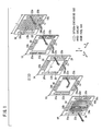
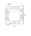
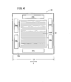
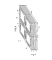
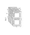
- a plurality of the fuel cell stacks 10 are used to selectively form a first assembly 50, a second assembly 52, a third assembly 54, and a fourth assembly 56 as described later on with reference to FIGS. 5 through 8 depending on conditions for installing the fuel cell stacks 10 in the vehicle. The installation conditions will be described later on.
- the first assembly 50 is formed by juxtaposing two fuel cell stacks 10 adjacent to each other.
- the stacking direction of the fuel cell stacks 10 indicated by an arrow A is oriented substantially vertically.
- the first assembly 50 has a width of 2 x L2, and a depth of L2, and a height of H.
- the height (H) can be adjusted by changing the number of unit cells stacked to form each of the fuel cell stacks 10.
- the second assembly 52 is formed by arranging four fuel cell stacks 10 adjacent to each other such that the second assembly 52 has a square shape in a plan view looking in a direction indicated by an arrow S.
- the stacking direction of the fuel cell stacks 10 indicated by an arrow A is oriented substantially vertically.
- the second assembly 52 has a width of 2 x L2, and a depth of 2 x L2, and a height of H.
- the height (H) can be adjusted by changing the number of unit cells stacked to form each of the fuel cell stacks 10.
- the third assembly 54 is formed by juxtaposing two fuel cell stacks 10 adjacent to each other.
- the stacking direction of the fuel cell stacks 10 indicated by an arrow A is oriented substantially horizontally.
- the third assembly 54 has a width of 2 x L2, a depth of L0, and a height of L2.
- the depth (L0) can be adjusted by changing the number of unit cells stacked to form each of the fuel cell stacks 10.
- the fourth assembly 56 is formed by arranging four fuel cell stacks 10 adjacent to each other such that the fourth assembly 56 has a square shape in a front view looking in a direction indicated by an arrow S.
- the stacking direction of the fuel cell stacks 10 indicated by an arrow A is oriented substantially horizontally.
- the fourth assembly 56 has a width of 2 x L2, a depth of L0, and a height of 2 x L2.
- the depth (L0) can be adjusted by changing the number of unit cells stacked to form each of the fuel cell stacks 10.
- an oxygen-containing gas such as air, a fuel gas such as a hydrogen-containing gas, and a coolant such as pure water, an ethylene glycol or an oil are supplied to the unit cells 12 of the fuel cell stack 10.
- the oxygen containing gas supplied to the oxygen-containing gas supply passage 20a extending in the direction indicated by the arrow A flows into the oxygen-containing gas supply passage 32 of the first separator 16 as shown in FIGS. 1 and 4.
- the oxygen-containing gas flows through the oxygen-containing gas flow passage 32 in the direction indicated by the arrow B along the cathode 30 of the membrane electrode assembly 14.
- the fuel gas is supplied to the fuel gas supply passage 22a extending in the direction indicated by the arrow A, and flows into the fuel gas flow passage 34.
- the fuel gas flows through the fuel gas flow passage 34 in the direction indicated by the arrow B along the anode 28 of the membrane electrode assembly 14.
- the oxygen-containing gas supplied to the cathode 30, and the fuel gas supplied to the anode 28 are consumed in the electrochemical reactions at catalyst layers of the cathode 30 and the anode 28 for generating electricity (see FIG. 2).
- the oxygen-containing gas After the oxygen-containing gas is consumed at the cathode 30, the oxygen-containing gas flows into the oxygen-containing gas discharge passage 20b (see FIG. 4). Similarly, after the fuel gas is consumed at the anode 28, the fuel gas flows into the fuel gas discharge passage 22b (see FIG. 1).
- the coolant supplied to the coolant supply passage 24a flows into the coolant flow passage 36 of the second separator 18.
- the coolant flows through the coolant flow passage 36 in the vertically upward direction, and cools the membrane electrode assembly 14. Then, the coolant flows into the coolant discharge passage 24b.
- the anode 28 and the cathode 30 of the membrane electrode assembly 14 have a substantially square shape having the side length L1 in the range of 140 mm to 200 mm. Therefore, the anode 28 and the cathode 30 have sufficient surface areas for producing high power output required for vehicles without using a large number of unit cells stacked to form the fuel cell stack 10. Therefore, the dimension in the stacking direction of the overall fuel cell stack 10 is small.
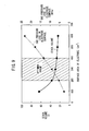
- FIG. 9 shows a relationship between the surface area of the anode 28 or the cathode 30, and the volume of the fuel cell stack 10, and a relationship between the surface area of the anode 28 or the cathode 30, and the gas pressure loss in the electrode surface.
- the surface area is less than 200 cm 2
- the stack volume needs to be significantly large for obtaining the desired high output.
- the surface area is greater than 400 cm 2 , the gas pressure loss in the electrode surface is large. Therefore, the surface area in the range of 200 cm 2 to 400 cm 2 is suitable for controlling the gas pressure loss in the electrode surface, and reducing the stack volume.
- FIG. 10 shows relationships between the aspect ratio of the electrode surface and the gas pressure loss in the electrode surface when the surface area of the electrode surface is 200 cm 2 , 300 cm 2 , and 400 cm 2 .
- the aspect ratio indicates the ratio of the longitudinal dimension to the lateral dimension in the electrode surface.
- the electrode surface having a substantially square shape effectively reduces the gas pressure loss in the electrode surface.
- the oxygen-containing gas flow passage 32 and the fuel gas flow passage 34 extend straight. Therefore, the gas pressure loss in the oxygen-containing gas and the fuel gas is small.
- Centers of the substantially square anode 28 and cathode 30 are substantially in alignment with centers of the substantially square first and second separators 16, 18. Therefore, the oxygen-containing gas supply passage 20a and the fuel gas supply passage 22a are formed symmetrically with the oxygen-containing gas discharge passage 20b and the fuel gas discharge passage 22b, respectively. Therefore, the reactions in the electrode surfaces are uniform, and the power generation performance can be improved effectively.
- the first and second separators 16, 18 have a substantially square shape having the side length L2 in the range of 200 mm to 300 mm.
- the width 2 x L2 is in the range of 400 mm to 600 mm.
- the width of the first assembly 50 is suitable for the vehicle application.
- the fuel cell stack 10 can be installed suitably in different positions in various types of vehicles easily.
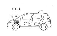
- the first assembly 50 is installed in a front box 62 of a minivan type vehicle 60.
- Two fuel cell stacks 10 are juxtaposed adjacent to each other to form the first assembly 50.
- the stacking direction of the unit cells in the first assembly 50 is oriented substantially vertically.
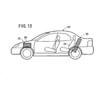
- the first assembly 50 is installed in a front box 66 of a sedan type vehicle 64.
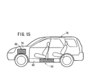
- the fourth assembly 56 may be installed behind a rear seat 68.
- the fourth assembly 56 is inclined substantially in parallel with the inclined rear seat 68.
- the stacking direction of the unit cells in the fourth assembly 56 is oriented substantially in a direction in which the vehicle 64 travels.
- the first assembly 50 is installed in a front box 72 of a one box type vehicle 70.
- the second assembly 52 may be installed in an under-floor region 74 of the vehicle 70.
- the stacking direction of the unit cells in the second assembly 52 is oriented substantially in a vertical direction.
- the first assembly 50 is installed in a front box 78 of a recreational vehicle 76.
- the second assembly 52 may be installed in an under-floor region 80 of the vehicle 76.
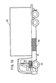
- the first assembly 50 is installed above front wheels 84 in a truck 82.
- the third assembly 54 may be installed in an under-floor region 86 of the truck 82.
- the stacking direction of the unit cells in the third assembly 54 is oriented substantially in a direction in which the truck 82 travels.
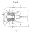
- the second assembly 52 is installed in an under-floor region 90 of a bus 88.
- the first assembly 50 or the third assembly 54 may be installed in a rear region 92 of the bus 88.
- the fourth assembly 56 may be installed at the back of the bus 88, or the second assembly 52 may be installed in a ceiling region 96 of the bus 88.
- the fuel cell stack 10 can be installed in the various types of vehicles 60, 64, 70, 76, 82, and 88. Depending on installation conditions, the fuel cell stack 10 is selectively assembled into any of the first through fourth assemblies 50, 52, 54, and 56. Therefore, the design, development, equipment for producing the dedicated fuel cell stack 10 for each type of the vehicles are not necessary. Since the unit cell 12 having the same structure can be applicable to various types of vehicles, the production cost of the fuel cell stack 10 is significantly reduced.
- the fuel cell stack 10 can be used in a large vehicle such as the truck 82 or the bus 88 which requires a large output, simply by increasing the number of the unit cells 12 in the first assembly 50, the second assembly 52, the third assembly 54, or the fourth assembly 56. It is not necessary to change the design of the electrode surface, such as the surface area of the anode 28 or the cathode 30 for obtaining the large output. Therefore, with the simple structure, the fuel cell stack 10 can be produced economically.
- the oxygen-containing gas supply passage 20a, the fuel gas supply passage 22a, the oxygen-containing gas discharge passage 20b, and the fuel gas discharge passage 22b extend through two parallel side portions of the first and second separators 16, 18 in the stacking direction, and a coolant supply passage 24a and a coolant discharge passage 24b extend through other two parallel side portions of the separators 16, 18 in the stacking direction. Therefore, the surfaces of the separators 16, 18 can be utilized efficiently, and the size of the overall fuel cell stack 10 can be reduced easily.
- the electrodes have a substantially square shape having a side length in the range of 140 mm to 200 mm
- the separators have a substantially square shape having a side length in the rage of 200 mm to 300 mm. Therefore, the size of the overall fuel cell stack can be reduced effectively.
- the fuel cell stack can be installed in different positions in various types of vehicles.
Landscapes
- Engineering & Computer Science (AREA)
- Life Sciences & Earth Sciences (AREA)
- Sustainable Development (AREA)
- Sustainable Energy (AREA)
- Chemical & Material Sciences (AREA)
- Chemical Kinetics & Catalysis (AREA)
- Manufacturing & Machinery (AREA)
- Electrochemistry (AREA)
- General Chemical & Material Sciences (AREA)
- Transportation (AREA)
- Mechanical Engineering (AREA)
- Power Engineering (AREA)
- Combustion & Propulsion (AREA)
- Fuel Cell (AREA)
- Arrangement Or Mounting Of Propulsion Units For Vehicles (AREA)
Applications Claiming Priority (2)
| Application Number | Priority Date | Filing Date | Title |
|---|---|---|---|
| JP2002215710 | 2002-07-24 | ||
| JP2002215710A JP2004063099A (ja) | 2002-07-24 | 2002-07-24 | 車載用燃料電池スタック |
Publications (2)
| Publication Number | Publication Date |
|---|---|
| EP1385227A2 true EP1385227A2 (fr) | 2004-01-28 |
| EP1385227A3 EP1385227A3 (fr) | 2006-12-20 |
Family
ID=29997252
Family Applications (1)
| Application Number | Title | Priority Date | Filing Date |
|---|---|---|---|
| EP03254609A Ceased EP1385227A3 (fr) | 2002-07-24 | 2003-07-24 | Empilement de piles à combustible pour un véhicule |
Country Status (4)
| Country | Link |
|---|---|
| US (1) | US7595125B2 (fr) |
| EP (1) | EP1385227A3 (fr) |
| JP (1) | JP2004063099A (fr) |
| CA (1) | CA2435899C (fr) |
Families Citing this family (10)
| Publication number | Priority date | Publication date | Assignee | Title |
|---|---|---|---|---|
| US7404878B2 (en) * | 2003-03-31 | 2008-07-29 | Chlorine Engineers Corp., Ltd. | Gas diffusion electrode assembly, bonding method for gas diffusion electrodes, and electrolyzer comprising gas diffusion electrodes |
| JP4565227B2 (ja) * | 2004-04-01 | 2010-10-20 | 株式会社クリーンクラフト | 電動バスの車体構造 |
| JP4753599B2 (ja) * | 2005-03-17 | 2011-08-24 | 本田技研工業株式会社 | 燃料電池 |
| US8257883B2 (en) * | 2005-08-03 | 2012-09-04 | GM Global Technology Operations LLC | Durability for the MEA and bipolar plates in PEM fuel cells using hydrogen peroxide decomposition catalysts |
| US7971670B2 (en) | 2005-10-25 | 2011-07-05 | Nissan Motor Co., Ltd. | Fuel cell electric vehicle |
| JP5474606B2 (ja) * | 2010-02-24 | 2014-04-16 | 本田技研工業株式会社 | 車載用燃料電池スタック |
| JP5585378B2 (ja) * | 2010-10-21 | 2014-09-10 | スズキ株式会社 | 空冷式燃料電池車両 |
| US10096844B2 (en) * | 2013-10-03 | 2018-10-09 | Hamilton Sundstrand Corporation | Manifold for plural fuel cell stacks |
| USD844562S1 (en) | 2016-10-05 | 2019-04-02 | General Electric Company | Fuel cell |
| CN114744229B (zh) * | 2022-03-25 | 2024-01-16 | 东风汽车集团股份有限公司 | 燃料电池模块、燃料电池系统、燃料电池动力系统及车辆 |
Family Cites Families (27)
| Publication number | Priority date | Publication date | Assignee | Title |
|---|---|---|---|---|
| US4431714A (en) * | 1982-07-01 | 1984-02-14 | The United States Of America As Represented By The United States Department Of Energy | Fuel cell design and assembly |
| JPS6093764A (ja) | 1983-10-28 | 1985-05-25 | Toshiba Corp | 燃料電池発電装置 |
| JPH03109126A (ja) * | 1989-09-21 | 1991-05-09 | Yamaha Motor Co Ltd | 燃料電池電気自動車 |
| DE4412451C1 (de) * | 1994-04-12 | 1995-09-28 | Daimler Benz Ag | Anordnung eines Antriebsaggregats in einem Elektrofahrzeug |
| DE4412450A1 (de) * | 1994-04-12 | 1995-10-26 | Daimler Benz Ag | Anordnung eines Antriebsaggregats in einem Elektrofahrzeug |
| JP3595027B2 (ja) | 1994-10-21 | 2004-12-02 | トヨタ自動車株式会社 | 燃料電池およびその製造方法 |
| JP3256649B2 (ja) * | 1995-08-29 | 2002-02-12 | 三菱電機株式会社 | 固体高分子形燃料電池の製造方法及び固体高分子形燃料電池 |
| JPH09134732A (ja) | 1995-11-10 | 1997-05-20 | Tanaka Kikinzoku Kogyo Kk | 薄型導電性ガス不透過基板、その製造方法、燃料電池用スタック構成部材及び燃料電池用スタック |
| JPH10106610A (ja) * | 1996-09-30 | 1998-04-24 | Sanyo Electric Co Ltd | 燃料電池 |
| JPH1167259A (ja) | 1997-08-11 | 1999-03-09 | Ishikawajima Harima Heavy Ind Co Ltd | 燃料電池のスタック構造 |
| US5972530A (en) * | 1998-01-13 | 1999-10-26 | Electrochem, Inc. | Air-cooled, hydrogen-air fuel cell |
| JP3029419B2 (ja) * | 1998-06-30 | 2000-04-04 | 株式会社東芝 | 燃料電池用セパレータの製造方法及び燃料電池用セパレータ |
| JP2000100456A (ja) * | 1998-09-22 | 2000-04-07 | Aisin Seiki Co Ltd | 固体高分子電解質膜と電極の接合体の製造方法及び固体高分子電解質型燃料電池 |
| JP2000149974A (ja) | 1998-11-05 | 2000-05-30 | Matsushita Electric Ind Co Ltd | 電気自動車 |
| DE19964565B3 (de) * | 1998-11-26 | 2017-07-06 | Kabushiki Kaisha Toshiba | Polymer-Elektrolyt-Brennstoffzellenstapel |
| US6223843B1 (en) * | 1998-12-16 | 2001-05-01 | General Motors Corporation | Electrochemical propulsion system |
| JP3769958B2 (ja) * | 1998-12-24 | 2006-04-26 | 三菱電機株式会社 | 燃料電池 |
| US6420061B1 (en) * | 1999-02-23 | 2002-07-16 | Honda Giken Kogyo Kabushiki Kaisha | Fuel cell stack |
| US6635378B1 (en) * | 1999-08-16 | 2003-10-21 | Hybrid Power Generation System, Llc | Fuel cell having improved condensation and reaction product management capabilities |
| US6613470B1 (en) * | 1999-09-01 | 2003-09-02 | Honda Giken Kogyo Kabushiki Kaisha | Solid polymer electrolyte fuel cell stack |
| US6368739B1 (en) * | 1999-09-08 | 2002-04-09 | Sofco | Joined solid oxide fuel cell stacks and method for fabricating same |
| JP3646024B2 (ja) * | 1999-09-24 | 2005-05-11 | ダイハツ工業株式会社 | 燃料電池装置 |
| JP2001118592A (ja) * | 1999-10-18 | 2001-04-27 | Matsushita Electric Ind Co Ltd | 高分子電解質型燃料電池及び電池スタック |
| JP3777981B2 (ja) * | 2000-04-13 | 2006-05-24 | トヨタ自動車株式会社 | 車両用電源装置 |
| CA2351871A1 (fr) | 2000-06-29 | 2001-12-29 | Ballard Power Systems Inc. | Plaques de champ cannelees pour piles a combustible liquide |
| JP2002025570A (ja) * | 2000-07-04 | 2002-01-25 | Sekisui Chem Co Ltd | 燃料電池用セパレータの処理方法及び燃料電池 |
| JP2002050391A (ja) * | 2000-08-02 | 2002-02-15 | Honda Motor Co Ltd | 燃料電池システム |
-
2002
- 2002-07-24 JP JP2002215710A patent/JP2004063099A/ja active Pending
-
2003
- 2003-07-23 CA CA2435899A patent/CA2435899C/fr not_active Expired - Fee Related
- 2003-07-24 US US10/626,225 patent/US7595125B2/en not_active Expired - Fee Related
- 2003-07-24 EP EP03254609A patent/EP1385227A3/fr not_active Ceased
Non-Patent Citations (1)
| Title |
|---|
| None |
Also Published As
| Publication number | Publication date |
|---|---|
| US20040101739A1 (en) | 2004-05-27 |
| EP1385227A3 (fr) | 2006-12-20 |
| CA2435899C (fr) | 2010-07-06 |
| US7595125B2 (en) | 2009-09-29 |
| CA2435899A1 (fr) | 2004-01-24 |
| JP2004063099A (ja) | 2004-02-26 |
Similar Documents
| Publication | Publication Date | Title |
|---|---|---|
| JP4630529B2 (ja) | 燃料電池システム | |
| US8003278B2 (en) | Fuel cell | |
| US7326485B2 (en) | Fuel cell with a seal tightly in contact with an electrode for preventing leakage of a reactant gas | |
| US20170149071A1 (en) | Bipolar plate for a fuel cell and fuel cell stack including a fuel cell | |
| US9701192B2 (en) | Fuel cell vehicle | |
| EP1239530A2 (fr) | Assemblage de piles à combustible à électrolyte polymère solide, empilement de piles à combustible et procédé pour la fourniture de gaz de réaction dans l'assemblage des piles à combustible | |
| US7695845B2 (en) | Fuel cell | |
| US20050019643A1 (en) | Fuel cell stack | |
| US6420061B1 (en) | Fuel cell stack | |
| JP3971969B2 (ja) | 固体高分子型燃料電池 | |
| US7569301B2 (en) | Fuel cell | |
| US12362370B2 (en) | Humidifier for fuel cell | |
| US20060024561A1 (en) | Fuel cell stack | |
| US7595125B2 (en) | Fuel cell stack for vehicle | |
| US7393607B2 (en) | Fuel cell and fuel cell stack | |
| CN109980248B (zh) | 燃料电池堆 | |
| US7572538B2 (en) | Fuel cell | |
| US20050158599A1 (en) | Fuel cell | |
| US7846589B2 (en) | Fuel cell having separator with cell voltage terminal | |
| JP2000311696A (ja) | 燃料電池スタック | |
| US8053125B2 (en) | Fuel cell having buffer and seal for coolant | |
| JP4507453B2 (ja) | 燃料電池のマニホールド | |
| US7413825B2 (en) | Fuel cell | |
| US20040038103A1 (en) | Solid polymer electrolyte fuel cell assembly | |
| JP2004134130A (ja) | 燃料電池スタック |
Legal Events
| Date | Code | Title | Description |
|---|---|---|---|
| PUAI | Public reference made under article 153(3) epc to a published international application that has entered the european phase |
Free format text: ORIGINAL CODE: 0009012 |
|
| AK | Designated contracting states |
Kind code of ref document: A2 Designated state(s): AT BE BG CH CY CZ DE DK EE ES FI FR GB GR HU IE IT LI LU MC NL PT RO SE SI SK TR |
|
| AX | Request for extension of the european patent |
Extension state: AL LT LV MK |
|
| PUAL | Search report despatched |
Free format text: ORIGINAL CODE: 0009013 |
|
| AK | Designated contracting states |
Kind code of ref document: A3 Designated state(s): AT BE BG CH CY CZ DE DK EE ES FI FR GB GR HU IE IT LI LU MC NL PT RO SE SI SK TR |
|
| AX | Request for extension of the european patent |
Extension state: AL LT LV MK |
|
| 17P | Request for examination filed |
Effective date: 20070126 |
|
| AKX | Designation fees paid |
Designated state(s): DE GB |
|
| 17Q | First examination report despatched |
Effective date: 20071107 |
|
| STAA | Information on the status of an ep patent application or granted ep patent |
Free format text: STATUS: THE APPLICATION HAS BEEN REFUSED |
|
| 18R | Application refused |
Effective date: 20141020 |